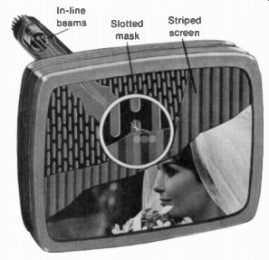
Television means to see at a distance." In our practical television system, the visual information in the scene is converted to an electric video signal for transmission to the receiver. Then the image is reassembled on the fluorescent screen of the picture tube (Fig. 1-1). In monochrome television, the picture is reproduced as shades of white, gray, and black. In color television, the main parts of the picture are reproduced in all their natural colors as combinations of red, green, and blue.
Originally, the techniques of television were developed for commercial broad casting, which started in 1941. The ability to reproduce pictures electronically has proved so useful though that many more applications of television are used now for education, industry, business, and visual communications in general. The main applications are described briefly in the following topics: 1-1 Television broadcasting 1-2 Television broadcast channels 1-3 Color television 1-4 Cable television (CATV) 1-5 Closed-circuit television (CCTV) 1-6 Picture phone 1-7 Facsimile 1-8 Satellites for worldwide television 1-9 CRT numerical displays 1-10 Video recording 1-11 Development of television broadcasting
FIGURE 1-1 IMAGE ON FLUORESCENT SCREEN OF COLOR PICTURE TUBE IN TELEVISION
RECEIVER (RCA)
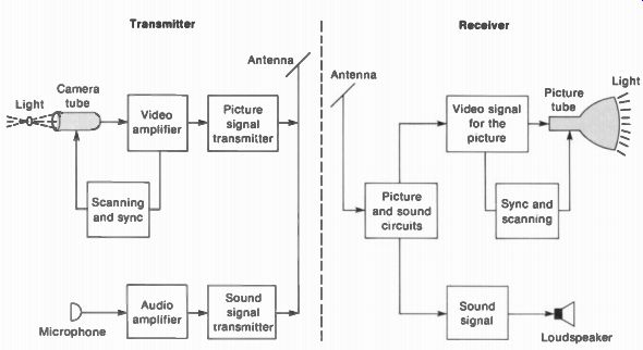
FIGURE 1-2 BLOCK DIAGRAM OF THE TELEVISION BROADCASTING SYSTEM.
1-1 Television Broadcasting
The term "broadcasting" means to send out in all directions. As illustrated in Fig. 1-2, the transmitting antenna radiates electromagnetic radio waves that can be picked up by the receiving antenna. For commercial television broad cast stations, the service area is about 25 to 75 mi in all directions from the transmitter. The radiation is in the form of two rf carrier waves, modulated by the desired information. Amplitude modulation (AM) is used for the picture signal. However, frequency modulation (FM) is used for the sound signal.
Referring to Fig. 1-2, we see that the desired sound for the televised program is converted by the microphone to an audio signal, which is amplified for the sound-signal transmit ter. For transmission of the picture, the camera tube converts the visual information into electrical signal variations. A camera tube is a cathode-ray tube with a photoelectric image plate. A common type is the vidicon camera tube shown in Fig. 1-3.
The electrical variations from the camera tube become the video signal,* which contains the desired picture information. The video signal is amplified and coupled to the picture-signal transmitter for broadcasting to receivers in the service area.
Separate carrier waves are used for the picture signal and sound signal, but they are radiated by one transmitting antenna. Further more, the picture and sound signals are included in the broadcast channel for each station. A television channel for a commercial broadcast station is made 6 MHz wide to include both the picture and sound. At the receiver also, one antenna is used for the picture and sound signals.
The receiving antenna intercepts the radiated picture and sound carrier signals, which are then amplified and detected in the receiver.
The detector output includes the desired video signal containing the information needed to reproduce the picture. Then the recovered video signal is amplified and coupled to a picture tube that converts the electric signal back into light.
Reproducing the picture. The picture tube in Fig. 1-4 is very similar to the cathode-ray tube used in the oscilloscope. The glass envelope contains an electron-gun structure that produces a beam of electrons aimed at the fluorescent screen. When the electron beam strikes the screen, it emits light.
*Video is Latin for see audio means "hear."
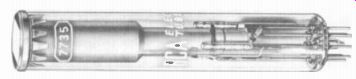
FIGURE 1-3 VIDICON CAMERA TUBE. LENGTH IS 6 IN. (RCA)
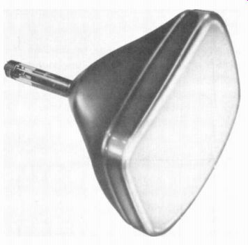
FIGURE 1-4 MONOCHROME PICTURE TUBE TYPE NUMBER 18VAUP4 SCREEN DIAGONAL IS
18 IN THE P4 INDICATES WHITE PHOSPHOR SCREEN ( SYLVANIA ELECTRIC PRODUCTS)
When the signal voltage makes the control grid less negative, the beam current is increased, making the spot of light on the screen brighter. More negative grid voltage reduces the brightness. If the grid voltage is negative enough to cut off the electron-beam current at the picture tube, there will be no light. This state corresponds to black. A color picture tube has three electron guns for the tricolor screen. The picture tube is also called a kine-scope or a CRT. Its function is to convert the video signal into a picture.
Scanning and synchronizing. In order for the camera tube to convert the picture information into video signal, the image is dissected into a series of horizontal lines. Similarly, the picture tube reassembles the image line by line. These horizontal lines are produced by making the electron beam scan across the screen. There are 525 lines per picture frame. In addition to this horizontal scanning, vertical scanning is necessary to spread the lines from top to bottom of the screen. There are 30 complete picture frames per second.
Furthermore, the scanning at the camera tube and picture tube must be synchronized, or timed, with respect to the video signal. The synchronization is necessary to reassemble the picture information on the correct lines. These functions are provided by the block of scanning and synchronizing circuits shown in Fig. 1-2 for the transmitter and receiver. The term "synchronizing" is usually abbreviated sync.
Most programs are produced live in the studio but recorded on video tape at a convenient time, to be shown later. The quality is so good that the picture looks practically the same as a live program. The studio also has projectors to use 35-mm still slides, opaque slides, and motion-picture film, either 16 or 35 mm, as the program source.
For remote pickups, as in broadcasting a sports event, the signal is relayed to the studio for broadcasting in the assigned channel. When there is a national hookup for important pro grams, each station in the network receives video signal by intercity relay links, usually leased from the telephone company. A system for satellite relay stations covering the country is being developed for this nationwide television service.
1 - 2 Television Broadcast Channels
The band of frequencies assigned for transmission of the picture and sound signals is a television channel. Each television broadcast station is assigned by the Federal Communications Commission (FCC) a channel 6 MHz wide in one of the following frequency bands: 54 to 88 MHz, 174 to 216 MHz, and 470 to 890 MHz. The first and second bands are in that very high frequency (VHF) spectrum of 30 to 300 MHz originally used for television broadcasting. The band of 54 to 88 MHz includes channels 2 to 6, inclusive, which are the low-band VHF television channels; the band of 174 to 216 MHz includes channels 7 to 13, inclusive, which are the high band VHF television channels. See Table 1-1.
The band of 470 to 890 MHz is in the ultrahigh-frequency (UHF) spectrum of 300 to 3,000 MHz. This band includes the UHF television channels 14 to 83, inclusive. These have been added to the previous VHF television channels to provide more channels for the expanding television broadcast service.

TABLE 1-1 TELEVISION CHANNELS
In all bands, each television broadcast channel is 6 MHz wide. The 6-MHz bandwidth is needed for the picture carrier signal, which is amplitude-modulated by the wide range of video signal frequencies up to 4.2 MHz. For color broadcasts, a 3.58-MHz color video signal is combined with the monochrome video signal so that both can be transmitted as one picture carrier signal. Also included in the 6-MHz channel is the associated sound carrier signal.
The following notes apply to Table 1-1.
The band of 44 to 50 MHz was originally allocated as television channel 1, but it is now as signed to other services. The FM radio broadcast band of 88 to 108 MHz is just above channel 6, but this service is not related to television broadcasting. Between television channels 4 and 5 the frequencies skip from 72 to 76 MHz because this band of frequencies is assigned for other uses, including air navigation. More de tails on frequency allocations are listed in Appendix B at the back of the guide.
1-3 Color Television
The block diagram in Fig. 1-2 illustrates the television broadcasting system for monochrome. In color television, a color camera is necessary at the transmitter and a color picture tube at the receiver. The color camera provides video signal for the red, green, and blue picture information. A color picture tube has red, green, and blue phosphors on the viewing screen to reproduce the picture in color. A typical color picture tube is shown in Fig. 1-5. This type has three electron guns for the tricolor screen. The phosphors can be dot trios of red, green, and blue, or vertical stripes of color as in Fig. 1-1.
Then each gun produces an electron beam to illuminate the red, green, or blue phosphor dots on the fluorescent screen.
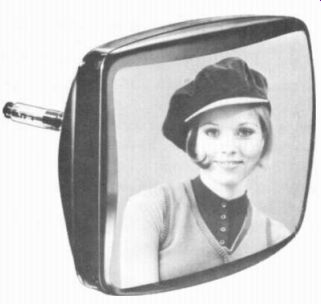
FIG 1-5 COLOR PICTURE TUBE TYPE NUMBER 18VATP22. THE P22 INDICATES SCREEN
WITH RED. GREEN. AND BLUE PHOSPHORS. (ZENITH CORPORATION)
Although the camera and picture tube operate with red, green, and blue, all other colors including white can be reproduced by combinations of these three colors. Further more, in commercial television, the red, green, and blue signals are combined for broadcasting.
The purpose is to transmit only a chrominance signal for color and a luminance signal the* contains the monochrome information. It is necessary to transmit the luminance signal so that monochrome receivers can reproduce the picture in black and white. The chrominance signal or chroma signal has all the information needed to reproduce the picture in color.
The luminance signal is called the Y video signal. The chrominance signal can be called the C signal. Actually the C signal is a modulated subcarrier of 3.58 MHz. This 3.58-MHz C signal modulates the assigned picture carrier in the standard 6-MHz television broadcast channel. Furthermore, the 3.58-MHz chrominance signal itself is modulated by two color video signals. The process of interweaving the Y signal for luminance with the 3.58-MHz color subcarrier signal for color is called multiplexing. In terms of the modulated chrominance signal, 3.58 MHz is the frequency for color in the television broadcast system.
Almost all programs now are broadcast in color. However, monochrome receivers use only the luminance signal to reproduce the picture in black and white. Color receivers use both the chrominance and luminance signals. On the screen of the picture tube, the color information is superimposed on the black-and-white picture.
It should be noted that the color receiver can also reproduce the picture in monochrome. In fact, if you turn down the color control, or if the 3.58-MHz chrominance signal is missing, you will see a normal black-and-white picture.
1-4 Cable Television (CATV)
When practical radio transmission started in the year 1901, the low radio frequencies of about 100 kHz were used for long distances of hundreds to thousands of miles. As radio developed, higher frequencies were used for services requiring more bandwidth. Now we have television broadcasting in the VHF band of 30 to 300 MHz and the UHF band of 300 to 3,000 MHz.
However, the distance for wireless transmission becomes much shorter at these high frequencies. Broadcasting is practically limited to the line-of-sight distance between the transmitting and receiving antennas in the VHF and UHF bands. The useful service range is up to 75 mi for VHF stations and 25 to 35 mi for UHF stations.
Another problem in the VHF and UHF bands is that the wavelength is short enough to allow reflections of the signal by metal structures, such as bridges, steel buildings, and even airplanes. The result is multipath reception of the direct and reflected signals. In the picture, the multipath signals produce multiple images called ghosts.
In many cases, the problems of ghosts and weak signals are solved best by going back to the idea of sending signals by wire cable, as in a telephone system. A cable television system provides broadcasting service by a network of coaxial cables. The rf sound and picture carrier signals, including color, are distributed as standard 6-MHz channels to subscribers who pay for this service. Coaxial cable is used because its shielding eliminates pickup of interference or radiation by the lines. The cable supplies at least 1 mV of signal for a strong picture with no snow and no ghosts.
The block diagram in Fig. 1-6 illustrates the head end, trunk lines, and subscriber lines with the required amplifiers. The head end is the source of the signals for the trunk lines, which are the main distribution lines.
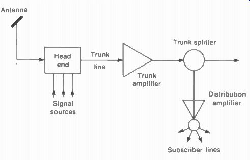
Figure 1-6 BLOCK DIAGRAM OF CABLE TV SYSTEM
Cable television started as an aid for improving reception in two opposite types of locations. The signal is weak in remote areas far from the broadcast transmitter or in a valley blocked by mountains. In big cities, the transmitter may be close, but tall buildings cause multipath reflections. For both types of location, cable television has solved the problem. Because of its advantages, cable television has grown to the point where it supplies 50 percent of the homes in some cities and rural areas. In addition to its ability to supply good signal.
Cable television provides more channels for the subscriber and new services besides commercial broadcast programs. See Table 1-2. In a typical cable TV service, there are usually 24 channels, in two sets of 12. Typical costs for the subscriber are an installation fee of $10 to $25 and a monthly charge of $4 to $6 per month for each receiver outlet.
The methods of broadcasting television signals by cable apply to several other applications, which are also important but on a smaller scale. For instance, in a hotel, motel, or apartment house, a master antenna can supply signal for all the outlets in the building. This system is called master-antenna television (MA N).
--------------

TABLE 1-2 PROGRAM SOURCES FOR CABLE TELEVISION ['May require extra subscription
fee from subscriber.]
TYPE | SOURCE
Commercial programs
Local community programs
Educational television
Local sports
Continuous time and weather
Continuous stock market quotations
Special events' -- theatre and sports
Off the air from broadcast channels
Local CATV studio
Direct wire from schools
Remote pickup from mobile microwave equipment
Local CATV studio
Local CATV studio
Local CATV studio or direct wire from theatre.
-------------
1-5 Closed-Circuit Television (CCTV)
In this system the video signal output from the camera is connected directly by cable to monitors at a remote position, where the picture is reproduced on the screen of the picture tube. A television monitor is a receiver without the 1 and IF circuits for tuning. About a 1-V peak-to-peak video signal is required for the monitor. There are any number of possible uses for CCTV in education, industry, medicine, and the home, but just a few are listed here: Education. One teacher for many classrooms, closeup views of experiments.
Industrial. Night watchman; remote inspection of materials; observe nuclear reactions.
Business. Train personnel; observe customers and salespeople.
Medicine. Show operation to students; ob serve patients in bed (Fig. 1-7). Traffic Control. Observe both ends of a tunnel or bridge; control freight traffic in railroad yard.
Home. Door monitor babysitter; observe per son sick in bed.
Surveillance. Stores; banks; traffic control; crime control.
Since the video signal is not transmitted, CCTV equipment need not follow the standards of television broadcasting. The cameras are very compact, as shown in Fig. 1-8. CCTV equipment is available for monochrome and color. The camera lenses are usually the same as for 16-mm film cameras. In some applications, the CCTV program is recorded, either on 16-mm film or on magnetic tape, to be played back at a later time. Furthermore the monitor display can be a large-screen projection unit, as shown in Fig. 1-9.
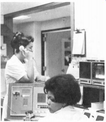
FIGURE 1-7 CLOSED-CIRCUIT TV IN HOSPITAL TO OBSERVE PATIENTS ( COLUMBIA-PRESBYTERIAN
MEDICAL CENTER)
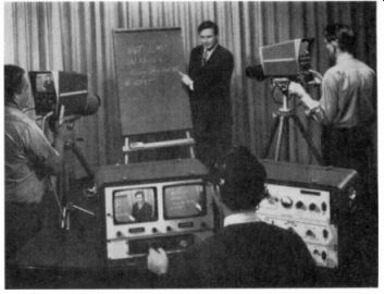
FIGURE 1-8 APPLICATION OF CLOSED-CIRCUIT TELEVISION (CCTV) IN TEACHING
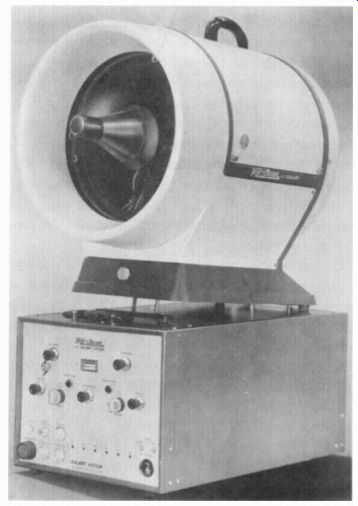
FIGURE 1-9 PROJECTION UNIT FOR TELEVISION PICTURE UP TO 9 12 FT. BASE OF
PROJECTOR IS 13.5 IN. WIDE. (KALART VICTOR CORPORATION)
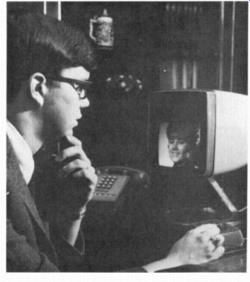
FIGURE 1-10 PICTURE-PHONE INSTALLATION ( BELL TELEPHONE LABORATORIES)
Theatre television. Special programs can be shown on a large screen by optical projection in a theatre, which usually presents important sports events that are not broadcast for the public. The theatre charges a box-office fee to see the show. . Usually, the video signal is supplied by coaxial cable, as another application of closed-circuit television. For color, three projection picture tubes are used, one each for red, green, and blue. Then the three color pictures are superimposed in register on one screen.
Projection of the light image on the face of the picture tube is usually by the Schmidt reflective system, preferred because of its efficiency for maximum brightness. This method is adopted from the Schmidt astronomical camera, which uses a spherical mirror to reflect and enlarge the image. With 80 kV on the anode of the picture tube, there is enough light for a picture 20 x 15 ft, at a projection throw distance of 80 ft. The same idea of projection television can be used for a home video theatre with a screen 4 x 3 ft.
Pay television. The idea of charging a fee for special programs is pay TV, box-office TV, or subscription TV. Besides theatre television, this service is also provided on an experimental basis in hotels and to homes in some areas. The features include first-run films, sports events, and cultural programs. Distribution of the signal can be by cable or over-the-air transmission in a particular channel. At the receiver, a special decoder or un-scrambler is used that enables the receiver to produce the picture and to record the charge made for the program.
1-6 Picture Phone
This system adds television to the telephone service, so that we can see as well as hear each other. As shown in Fig. 1-10, a picture-phone installation includes a CRT display unit and small camera for the picture with a 12-button phone.
The picture has 250 lines per frame, 30 frames per second, and video frequencies limited to 1 MHz. However, more scanning lines and a wider video-frequency bandwidth may be used for a picture with better resolution. Picture-phone service is also useful for showing still pictures of drawings, photographs, and equipment.
1-7 Facsimile
This application is the electronic transmission of visual information, usually a still picture, over telephone lines. Facsimile is also called slow scan television. Since there is no motion in the scene, the scanning for facsimile can be relatively slow. Atypical rate is 360 scanning lines per minute. One important use is the facsimile mail service being used between New York City and Washington, D.C. by the U.S. Post Office. A typical facsimile unit is shown in Fig. 1-11.
1-8 Satellites for Worldwide Television
Transmission in the VHF and UHF bands is limited to the line-of-sight distance to the horizon.
Therefore, satellite stations circling the globe are necessary for television transmission over long distances. A satellite orbit is hundreds to thousands of miles above the earth. Satellites for worldwide communications are now an established part of television and telephone ser vice, operated in the United States by Communications Satellite Corporation (COMSAT) in cooperation with the 82-nation International Telecommunications Satellite (Intelsat) Consortium. There are satellites over the Atlantic, Pacific, and Indian oceans operating as relay stations between 40 ground stations around the world. The first satellite used for television was Telstar in 1962.
A further step for satellites is a domestic system in each country. In Canada, Anik 1 and Anik 2 are the first domestic satellites to provide communications between the east and west coasts for Canada and the United States, including Alaska. For television in the United States, work is being done on satellites to broadcast directly to receivers throughout the country, using the standard 6-MHz channels.
The Intelsat IV in Fig. 1-12 is a relay station for international communications, providing either 5,000 two-way phone circuits or 12 simultaneous color TV broadcasts. Typical transmission frequencies are 6,000 MHz for the up path to the satellite and 4,000 MHz for the down path to the ground station.
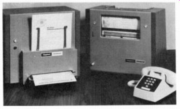
FIGURE 1-11 FACSIMILE UNIT FOR SENDING COPIES OF DOCUMENTS OVER TELEPHONE
LINES. (TELAUTOGRAPH CORPORATION)
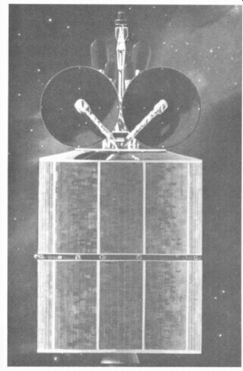
FIGURE 1-12 INTELSAT IV SATELLITE FOR INTERNA TIONAL COMMUNICATIONS (HUGHES
AIRCRAFTcom PANY)
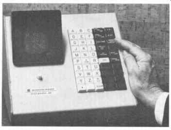
FIGURE 1-13 CRT NUMERICAL DISPLAY FOR STOCK QUOTATION SERVICE (BUNKER-RAMO)
The ground station converts the satellite signal to local standards for transmission on commercial TV broadcast channels. With different television standards in Europe and the United States, a converter at the ground station changes the video signal to the required form.
The scanning standards are 525 lines per frame and 30 frames per second in the United States, Canada, South America, and Japan. However, most of Europe uses 625 lines per frame and 25 frames per second. Furthermore, our color system uses the National Television Systems Committee (NTSC) method. In Europe, the Phase-A1 ternate-Line (PAL) system is generally used for color television. The converter at the ground station can change between scanning standards: from PAL to NTSC color or from NTSC to PAL color. More details on television standards throughout the world are listed in Appendix C.
1-9 CRT Numerical Displays
The cathode-ray tube used for reproducing the picture in television is basically an electronic display that can be used for many kinds of visual information. An example is the numerical display, shown in Fig. 1-13, for quoting stock prices as a financial service. Although it is a numerical display, the picture tube still requires video signal, scanning, and synchronizing. The video signal varies the intensity of the electron beam to illuminate the characters. The synchronizing signal regulates the scanning in accordance with a pre-established pattern to determine the shape for each digit or letter.
1-10 Video Recording
The video signal can be recorded on magnetic tape for picture reproduction, similar to audio tape recording for the reproduction of sound.
Figure 1-14 illustrates the elements of a magnetic tape recorder. The tape consists of very fine particles of magnetic iron oxide coated on a plastic base. The transport mechanism pulls the tape past the record-playback head. Since the head contains many turns of fine wire, its magnetic field reacts with the magnetic tape. On the recording position, signal current magnetizes the tape, with the same variations as the signal.
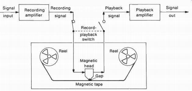
FIGURE 1-14 ESSENTIAL FUNCTIONS OF A REEL-TO-REEL TAPE RECORDER. THE TAPE
CAN ALSO BE IN A CASSETTE OR CARTRIDGE
On playback, the moving magnetic tape induces signal current in the head. The record-playback switch determines whether the machine records or plays back. Although a reel-to-reel recorder is shown here, the same functions apply to cassettes or cartridges that hold the tape.
The problem in video recording is the extreme ratio of highest to lowest signal frequencies. Compared with 20 to 20,000 Hz for audio signal. the video-frequency range is from 30 Hz to 4 MHz, approximately. High-frequency response is limited by the size of the gap in the head and by the speed of the tape. The nonmagnetic gap is usually silicon dioxide, which is similar to glass, with a width only 850 x 10^-9 cm.
To provide an effective increase in tape speed, rotating heads can be used. The relative head-to-tape speed is the writing speed.
Another technique is helical scan, where the head records diagonally across the width of the tape. Finally, the video-frequency bandwidth is reduced to about 2.5 MHz, for portable recorders.
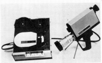
FIGURE 1-15 VIDEO TAPE RECORDER WITH HAND-HELD CAMERA 15 IN LONG. (SONY CORPORATION
OF AMERICA)
In all cases, the video is recorded as an FM signal on a carrier of approximately 5 MHz.
The main reason for the FM recording is to reduce amplitude distortion on playback that can be caused by mistracking of the rotating heads. The tape speed is generally 7 1/2 in./s.
Almost all television studio programs are taped, but the picture quality is so good that it looks practically the same as a live program.
Professional video tape recorders generally use rotating heads with full video bandwidth of 4 MHz on 1-in, tape for monochrome or color.
However, smaller and lower-priced video tape recorders using 1/2-in. tape are made for closed circuit TV or for use in the home. They can record and play back programs on a television monitor or a receiver, in monochrome and color.
In addition, small portable cameras are available for a complete television system with the recorder (Fig. 1-15). These portable systems are also used for taping television programs from a remote location away from the broadcast studio.
A reel-to-reel recorder is shown in Fig. 1-15, but video cassettes are also used.
In addition to video tape recording (VTR), playback units also use video disk recording (VDR). The disks are similar to phonograph records, but a much greater frequency response is needed for video signal. As one example, an 8-in, disk rotating at 1,500 rpm has a playback time of 10 min. Either a mechanical stylus can be used or the disk is scanned optically by a laser light beam. The video disks are much more economical than magnetic tapes. However, the disks are generally used for playback only, while video tape is for recording and playback.
1-11 Development of Television Broadcasting
The start can be taken from the year 1945 when the Federal Communications Commission (FCC) assigned the VHF channels 2 to 13 now used for commercial television. Originally, channel 1 at 44 to 50 MHz was also allocated, but these frequencies were assigned in 1948 to mobile radio services because of interference problems.
The first popular television receiver, RCA model 630 TS, was marketed in 1946. This was a 30-tube receiver, with a 10-in, round screen.
Two important circuits for television first used in this receiver are as follows:
1. Flyback high-voltage supply. This circuit produces anode voltage for the picture tube, which is needed for brightness, from the sharp change in current during horizontal retrace. Unless the horizontal scanning circuits are operating, there is no high voltage for the picture tube and no light on the screen.
2. Horizontal automatic frequency control (AFC). This circuit improves the horizontal synchronization. With horizontal AFC, the picture will break into diagonal segments if it is out of sync.
These circuits are still used in practically all television receivers, for color or monochrome, that use tubes or transistors.
In 1947, R. B. Dome of General Electric proposed the method of intercarrier sound for television receivers. In this system, the sound signal in the receiver is detected as the 4.5-MHz difference frequency between the rf picture and sound carrier frequencies. The advantage lies in easier tuning of the sound signal, especially on UHF channels. All television receivers now use intercarrier sound, with a common IF amplifier for both the picture and sound signals. As a result, there will be no picture and no sound if the picture IF amplifier is not operating.
Color television broadcasting developed from earlier systems that suffered from mechanical problems, incompatible scanning standards, and excessive bandwidth. In 1949, experimental systems were demonstrated to the FCC by Columbia Broadcasting System (CBS) and by Radio Corporation of America (RCA). The CBS method used a color wheel rotating in front of a black-and-white picture tube. The color information was produced in a sequential pattern that required scanning frequencies different from the monochrome standards for a 3-MHz broadcast channel. The RCA method was all electronic and compatible with monochrome broadcasting. The FCC approved the CBS color system for commercial broadcasting because of excellent color reproduction. However, this approval was soon withdrawn in favor of the color system developed by the National Television Systems Committee (NTSC). This committee, as part of the Electronic Industries Association EIA, also developed the standards used for black-and-white television. The NTSC system adopted by the FCC in 1953 is the method used now for all commercial color television in the United States and in most of the countries of North and South America. The details of the NTSC system with its 3.58-MHz chrominance signal are described in Sect. 8 on Color Television.
In 1952, the UHF channels 14 to 83 were assigned by the FCC to provide for more television broadcast stations. Some of these channels are reserved for educational television operated by schools.
In 1962, worldwide television transmission was made possible by the use of satellites circling the earth. The Telstar project of American Telephone and Telegraph Company was the start. Now there are several satellites for world wide communications, operated by COMSAT in the United States and by Intelsat internationally.
In 1964 a federal law was passed that all television receivers shipped in interstate commerce must have rf tuners for both the VHF and UHF channels. In 1972, it was required that the UHF tuning must be as accurate as the VHF tuning. These laws were passed to increase the use of the UHF television broadcast channels. What was the channel 1 position on the VHF tuner is now used for switching on the UHF tuner.
SUMMARY
1. A commercial television broadcast station uses a 6-MHz channel for the AM picture carrier signal and FM sound carrier signal. Channels 2 to 13 are in the VHF band; channels 14 to 83 are in the UHF band.
2. The camera tube converts the light image into video signal voltage. The picture tube converts the video signal back into light to reproduce the picture.
3. In color television, 3.58 MHz is the frequency used for the chrominance signal. A color picture tube has red, green, and blue phosphors to reproduce the picture in all its natural colors.
4. In cable television (CATV), the rf picture and sound signals are distributed by a network of coaxial cable to subscribers who pay for this service.
5. In closed-circuit television (CCTV), the video and audio signals are connected directly by coaxial cable to monitors or receivers at a remote location.
6. Facsimile, or slow-scan television, is a system for transmitting still pictures over telephone lines.
7. Satellites are used as relay stations to provide worldwide television broadcasting.
8. In video tape recording, the video signal is recorded on magnetic tape, similar to the process of tape recording for audio signal.
Self-Examination (Answers at back of guide)
Answer True or False.
1. The picture carrier signal is AM, but the sound carrier signal is FM.
2. Channel 6 is 66 to 72 MHz.
3. In color television, 3.58 MHz is the frequency of the chrominance signal.
4. A picture tube converts video signal to audio signal.
5. A camera tube converts a light image into video signal.
6. With a flyback high-voltage supply, there cannot be any light on the screen of the picture tube unless the horizontal scanning circuits are operating.
7. The range of video signal frequencies is much greater than for audio frequencies.
8. For intercarrier sound receivers, the frequency for the sound signal is 4.5 MHz.
9. Facsimile is for still pictures, but television can show motion in the scene.
10. A television picture frame consists of 525 horizontal scanning lines, repeated every 1 3 s.
Essay Questions
1. Define the following abbreviations: AM, FM, FCC, NTSC, EIA, VTR, CATV, CCTV, and AFC.
2. Give the frequency bands for the following channels: 2, 6, 7, 13, 14. and 83.
3. Give two uses for closed-circuit television.
4. Describe briefly the functions of the camera tube and picture tube.
5. Define intercarrier sound.
6. Describe briefly four applications of the principles of a television picture.