Television is basically a system for reproducing a still picture such as a snapshot. However, the pictures are shown one over the other fast enough to give the illusion of motion. One picture frame by itself is just a group of small areas of light and shade.
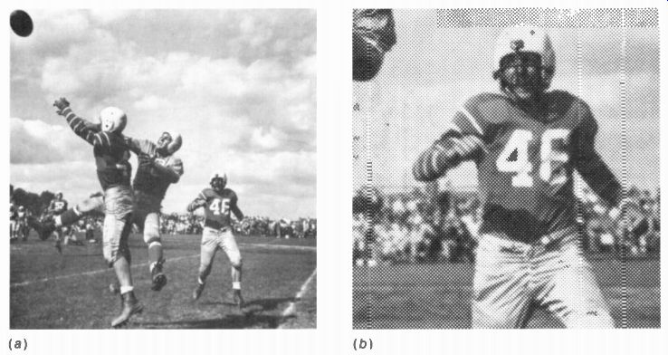
This structure can be seen in Fig. 2-1 b. which is a magnified view to show the details of the still picture in a. All the details with varying light and dark spots provide the video signal for the picture information.
We consider black-and-white or monochrome pictures first because these requirements apply for color also. A color television picture is just a monochrome picture with color added in the main areas of the scene. More details are described in the following topics:
2-1 Picture elements 2-2 Horizontal and vertical scanning 2-3 Motion pictures 2-4 Frame and field frequencies 2-5 Horizontal and vertical scanning frequencies 2-6 Horizontal and vertical synchronization 2-7 Horizontal and vertical blanking 2-8 The 3.58-MHz color signal 2-9 Picture qualities 2-10 The 6-MHz television broadcast channel 2-11 Standards of transmission
2-1 Picture Elements
A still picture is fundamentally an arrangement of many small dark and light areas. In a photographic print, fine grains of silver provide the differences in light and shade needed to reproduce the image. When a picture is printed from a photoengraving, there are many small black printed dots which form the image. Looking at the magnified view in Fig. 2-1b, we can see that the printed picture is composed of small elementary areas of black and white. This basic structure of a picture is evident in newspaper photographs. If they are examined closely, the dots will be seen because the picture elements are relatively large.
FIGURE 2-1 (a) A STILL PICTURE (b) MAGNIFIED VIEW TO SHOW PICTURE ELEMENTS
FIGURE 2-2 REPRODUCING A PICTURE BY DUPLICATING ITS PICTURE ELEMENTS
Each small area of light or shade is a picture element or picture detail. All the elements contain the visual information in the scene. If they are transmitted and reproduced in the same degree of light or shade as the original and in proper position, the picture will be reproduced.
As an example, suppose that we want to transmit an image of the black cross on a white background, shown at the left in Fig. 2-2, to the right side of the figure. The picture is divided into the elementary areas of black and white shown. Picture elements in the background are white, while the elements forming the cross are black. When each picture element is transmitted to the right side of the figure and reproduced in the original position with its shade of black or white, the image is duplicated.
2-2 Horizontal and Vertical Scanning
The television picture is scanned in a sequential series of horizontal lines, one under the other, as shown in Fig. 2-3. This scanning makes it possible for one video signal to include all the elements for the entire picture. At one instant of time, the video signal can show only one variation. In order to have video signal for all the variations of light and shade, all the picture details are scanned in a sequential order of time.
The scanning makes a television picture reproduction different from a photographic print. In a photo, the entire picture is reproduced at one time. In television, the picture is reassembled line after line and frame over frame. This factor of time is the reason why a television picture can appear with the line structure torn apart in diagonal segments and the frames rolling up or down the screen.
The scanning is done in the same way you read to cover all the words in one line and all the lines on the page. Starting at the top left in Fig. 2-3, all the picture elements are scanned in successive order, from left to right and from top to bottom, one line at a time. This method, called horizontal linear scanning, is used in the camera tube at the transmitter to divide the image into picture elements and in the picture tube at the receiver to reassemble the reproduced image.
The sequence for scanning all the picture elements is as follows:
1. The electron beam sweeps across one horizontal line, covering all the picture elements in that line.
2. At the end of each line, the beam is returned very quickly to the left side to begin scanning the next horizontal line. The return time is called retrace or flyback. No picture information is scanned during retrace be cause both the camera tube and picture tube are blanked out for this period. The retraces must be very rapid, therefore, since they are wasted time in terms of picture information.
3. When the beam is returned to the left side, its vertical position is lowered so that the beam will scan the next lower line and not repeat over the same line. This is accomplished by the vertical scanning motion of the beam, which is provided in addition to horizontal scanning.
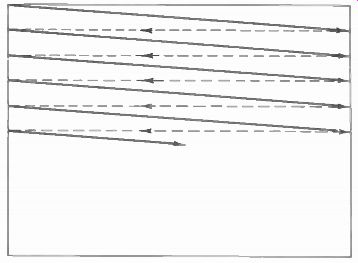
FIGURE 2-3 HORIZONTAL LINEAR SCANNING. SOLID LINES SHOW TRACE FROM LEFT TO
RIGHT: DASHED LINES FOR RETRACE FROM RIGHT TO LEFT.
Lines per frame. The number of scanning lines for one complete picture should be large in order to include the highest possible number of picture elements and, therefore, more details.
However, other factors limit the choice, and it has been standardized at a total of 525 scanning lines for one complete picture or frame. This number is the optimum number of scanning lines per frame for the standard 6-MHz band width of the television broadcast channels.
Frames per second. Note that the beam moves slowly downward as it scans horizontally.
This vertical scanning motion is necessary so that the lines will not be scanned one over the other. The horizontal scanning produces the lines left to right, while the vertical scanning spreads the lines to fill the frame top to bottom.
The vertical scanning is at the rate of 30 Hz for the frame frequency of 30 frames per second. This value is exactly one-half the ac power line frequency of 60 Hz. The frame rate of 30 per second means that 525 lines, for one complete frame, are scanned in 1/30 s.
2-3 Motion Pictures
With all the picture elements in the frame televised by means of the scanning process, it is also necessary to present the picture to the eye in such a way that any motion in the scene appears on the screen as a smooth and continuous change. In this respect the television system is very similar to motion-picture practice.
Figure 2-4 shows a strip of motion-picture film. Note that it consists of a series of still pictures with each picture frame differing slightly from the preceding one. Each frame is projected individually as a still picture: but they are shown one after the other in rapid succession to produce the illusion of continuous motion.
In standard commercial motion-picture practice, 24 frames are shown on the screen for every second during which the film is projected.
A shutter in the projector rotates in front of the light source. The shutter allows the light to be projected on the screen when the film frame is still, but blanks out any light during the time when the next film frame is being moved into position. As a result, a rapid succession of still film frames is seen on the screen.
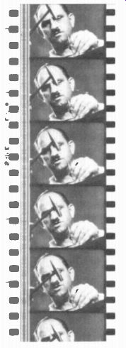
FIGURE 2-4 A STRIP OF MOTION-PICTURE FILM ( EASTMAN-KODAK CO.)
Persistence of vision. The impression made by any light seen by the eye persists for a small fraction of a second after the light source is removed. Therefore, if many views are presented to the eye during this interval of persistence of vision, the eye will integrate them and give the impression of seeing all the images at the same tine. It is this persistence effect that makes possible the televising of one basic element of a picture at a time. When the elements are scanned rapidly enough, they appear to the eye as a complete picture.
In addition, to create the illusion of motion, enough complete pictures must be shown during each second. This effect can be produced by having a picture repetition rate greater than 16 per second. The repetition rate of 24 pictures per second used in motion-picture practice is satisfactory and produces the illusion of motion on the screen.
Flicker in motion pictures. The rate of 24 frames per second, however, is not rapid enough to allow the brightness of one picture to blend smoothly into the next during the time when the screen is black between frames. The result is a definite flicker of light as the screen is made alternately bright and dark. This flicker is worse at higher illumination levels. In motion picture films, the problem of flicker is solved by running the film through the projector at a rate of 24 frames per second, but showing each frame twice so that 48 pictures are flashed on the screen during each second. A shutter is used to blank out light from the screen not only during the time when each frame is being changed, but once between. Then each frame is projected twice on the screen. There are 48 views of the scene during each second, and the screen is blanked out 48 times per second, al though there are still the same 24 picture frames per second. As a result of the increased blanking rate, flicker is eliminated.
2-4 Frame and Field Frequencies
A similar process is used in television to reproduce motion in the scene. Not only is each picture broken down into its many individual picture elements, but the scene is scanned rapidly enough to provide sufficient complete pictures or frames per second to give the illusion of motion, instead of the 24 rate in commercial motion-picture practice, however, the frame repetition rate is 30 per second in the television system. This repetition rate provides the required continuity of motion.
The picture repetition rate of 30 per second is still not rapid enough to overcome the problem of flicker at the light levels encountered on the picture tube screen. Again the solution is similar to motion-picture practice. Each frame is divided into two parts, so that 60 views of the scene are presented to the eye during each second. However, the division of a frame into two parts cannot be accomplished by the simple method of the shutter used with motion-picture film, because the picture is reproduced one element at a time in the television system. Instead, the same effect is obtained by interlacing the horizontal scanning lines in two groups, one with the odd-numbered lines and the other with the even-numbered lines. A group of odd or even lines is called a field.
The repetition rate of the fields is 60 per second, as two fields are scanned during one frame period of 1/30 s. In this way, 60 views of the picture are shown during 1 S. This repetition rate is fast enough to eliminate flicker.
The frame repetition rate of 30 is chosen in television, rather than the 24 of commercial motion pictures, because most homes in the United States are supplied with 60-Hz ac power.
Having the frame rate of 30 per second makes the field rate exactly equal to the power-line frequency of 60 Hz. In countries where the ac power-line frequency is 50 Hz, the frame rate is 25 Hz, making the field frequency 50 Hz. Television standards for the United States and other countries are compared in Appendix C at the back of the guide.
2-5 Horizontal and Vertical Scanning Frequencies
The field rate of 60 Hz is the vertical scanning frequency. This is the rate at which the electron beam completes its cycles of vertical motion, from top to bottom and back to top again, ready to start the next vertical scan. Therefore, vertical deflection circuits for either the camera tube or picture tube operate at 60 Hz. The time of each vertical scanning cycle for one field is 1 /60 s.
The number of horizontal scanning lines in a field is one-half the total 525 lines for a complete frame, since one field contains every other line. This results in 262.5, horizontal lines for each vertical field. Since the time for a field is 1 /60 s and since it contains 262.5 lines, the number of lines per second is 262.5 x 60 15,750.
Or, considering 525 lines for a successive pair of fields, which is a frame, we can multiply the frame rate of 30 by 525, which equals the same 15,750 lines scanned in 1 s.
This frequency of 15,750 Hz is the rate at which the electron beam completes its cycles of horizontal motion, from left to right and back to left again, ready to start the next horizontal scan.
Therefore, horizontal deflection circuits for either the camera tube or picture tube operate at 15,750 Hz.
The time for each horizontal scanning line is 1/157750 s. In terms of microseconds,
1,000,000 H time t is = 63.5
As approx 15,750
This time in microseconds indicates that the video signal for picture elements within a horizontal line can have high frequencies in the order of megahertz. If there were more lines, the scanning time would be shorter, resulting in higher video frequencies. Actually, in our 525-line system, the highest video frequency is limited to approximately 4 MHz because of the restriction of 6 MHz for the commercial television broadcast channels.
2-6 Horizontal and Vertical Synchronization
Time in scanning corresponds to distance in the image. As the electron beam in the camera tube scans the image, the beam covers different elements of the image and provides the corresponding picture information. Therefore, when the electron beam scans the screen of the picture tube at the receiver, the scanning must be exactly timed to assemble the picture information in the correct position. Otherwise, the electron beam in the picture tube can be scanning the part of the screen where a man's mouth should be while at that time the picture information being received corresponds to his nose. To keep the transmitter and receiver scanning in step with each other, special synchronizing signals must be transmitted with the picture information for the receiver. These timing signals are rectangular pulses used to control both transmitter and receiver scanning.
The synchronizing pulses are transmitted as a part of the complete picture signal for the receiver, but they occur during the blanking time when no picture information is transmitted. The picture is blanked out for this period while the electron beam retraces. A horizontal synchronizing pulse at the end of each horizontal line begins the horizontal retrace time, and a vertical synchronizing pulse at the end of each field begins the vertical retrace time. As a result. the receiver and transmitter scanning are synchronized. Without the vertical field synchronization, the reproduced picture at the receiver does not hold vertically, and it rolls up or down on the picture tube screen. If the scanning lines are not synchronized, the picture will not hold horizon tally, as it slips to the left or right and then tears apart into diagonal segments.
In summary, then, the horizontal line scanning frequency is 15,750 Hz, and the frequency of the horizontal synchronizing pulses is also 15,750 Hz. The frame repetition rate is 30 per second, but the vertical field-scanning frequency is 60 Hz, and the frequency of the vertical synchronizing pulses is also 60 Hz.
It should be noted that the scanning frequencies of 15,750 and 60 Hz are exact for monochrome but only approximate for color television. In color broadcasting, the horizontal line-scanning frequency is exactly 15,734.26 Hz, with 59.94 Hz for the vertical field frequency.
These exact scanning frequencies are used to minimize interference between the color subcarrier at exactly 3.579545 MHz and the intercarrier sound signal at exactly 4.5 MHz. However, the horizontal and vertical scanning frequencies can be considered generally as 15,750 and 60 Hz. The reason is that the deflection circuits are automatically synchronized at the required scanning frequencies for both monochrome and color broadcasting.
2-7 Horizontal and Vertical Blanking
In television, "blanking- means going to black.
As part of the video signal, blanking voltage is at the black level. Video voltage at the black level cuts off beam current in the picture tube to blank out light from the screen. The purpose of the blanking pulses is to make invisible the re traces required in scanning. Horizontal blanking pulses at 15,750 Hz blank out the retrace from right to left for each line. Vertical blanking pulses at 60 Hz blank out the retrace from bottom to top for each field.
The period of time for horizontal blanking is approximately 16 percent of each H line. The total time for H is 63.5 us, including trace and re trace. The blanking time for each line then is 63.5 x 0.16 = 10.2 is. This H blanking time means that the retrace from right to left must be completed within 10.2 us, before the start of visible picture information during the scan from right to left.
The time for vertical blanking is approximately 8 percent of each V field. The total time for V is 1/60s, including the downward trace and upward retrace. The blanking time for each field, then, is 1 /60 x 0.08 = 0.0013 s. This V blanking time means that, within 0.0013 s. the vertical retrace must be completed from bottom to top of the picture.
The retraces occur during blanking time because of synchronization of the scanning.
The synchronizing pulses coincide with the start of the retraces. Each horizontal synchronizing pulse is inserted in the video signal within the time of the horizontal blanking pulse. In summary, a blanking pulse comes first to put the video signal at black level; then a synchronizing signal occurs to start the retrace in scanning.
This sequence applies to blanking horizontal and vertical retraces.
2-8 The 3.58- MHz Color Signal
The system for color television is the same as for monochrome, but in addition the color information in the scene is used. This is accomplished by considering the picture information in terms of red, green, and blue. When the image is scanned at the camera tube, separate video signals are produced for the red, green, and blue picture information. Optical color filters separate the colors for the camera. For broadcasting in the standard 6-MHz television channel, however, the red, green, and blue color video signals are combined to form two equivalent signals, one for brightness and the other for color.
Specifically, the two transmitted signals are as follows:
1. Luminance Signal. Contains only brightness variations of the picture information, including fine details, as in a monochrome signal. The luminance signal is used to reproduce the picture in black and white.
This signal is generally labeled Y signal (not for yellow).
2. Chrominance Signal. Contains the color information. This signal is transmitted as the modulation on a subcarrier at 3.58 MHz for all stations. Therefore 3.58 MHz is the frequency for color. This is generally labeled C signal for chrominance, chroma, or color.
In a color television receiver, color signal is combined with luminance signal to recover the original red, green. and blue video signals.
These are then used for reproducing the picture in color on the screen of a color picture tube.
The color screen has phosphors that produce red, green. and blue fluorescence. All colors can be produced as mixtures of red, green, and blue. A typical color television picture is shown in color plate I. In monochrome receivers, the Y signal reproduces the picture in black and white. The 3.58-MHz color signal is just not used. In this case, 3.58 Mhz is filtered out of the video signal, to prevent interference with the monochrome picture.
As a result, the color and monochrome systems are completely compatible. When a program is televised in color, the picture is reproduced in color by color receivers, while monochrome receivers show the picture in black and white. Furthermore, programs televised in monochrome are reproduced in black and white by both monochrome and color receivers. The tricolor picture tube car also reproduce white by combining red, green, and blue.
2-9 Picture Qualities
Assuming it is synchronized to stay still, the reproduced picture should also have high brightness, strong contrast, sharp detail, and the correct proportions of height and width. These requirements apply for monochrome and color.
In addition, the color picture should have strong color or saturation, with the correct tints or hues.
Brightness. This is the overall or average intensity of illumination, which determines the background level in the reproduced picture. Individual picture elements can then vary above and below this average brightness level. Brightness on the screen depends on the amount of high voltage for the picture tube and its dc bias in the grid-cathode circuit. In television receivers, the brightness control varies the picture tube dc bias.
It should be noted that the fluorescent screen of the picture tube is illuminated on only one small spot at a time. Therefore, the brightness of the complete picture is much less than the actual spot illumination. The bigger the picture, the more light needed from the spot to produce enough brightness.
Contrast. By "contrast" is meant the difference in intensity between black-and-white parts of the reproduced picture, as distinguished from brightness, which is average intensity. The contrast range should be great enough to produce a strong picture, with bright white and dark black for the extreme intensity values. The amount of ac video signal deter mines the contrast of the reproduced picture. It is the ac signal amplitude that determines how intense the white will be, compared with black parts of the signal. In television receivers, the contrast control varies the peak-to-peak amplitude of the ac video signal coupled to the picture-tube grid-cathode circuit.
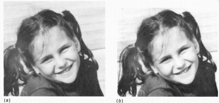
FIGURE 2-5 PICTURE QUALITY IMPROVES WITH MORE DETAIL (a) COARSE STRUCTURE
WITH FEW DETAILS AND POOR DEFINITION (b) FINE DETAIL AND GOOD DEFINITION
Keep in mind the fact that black in the picture is the same light level you see on the picture tube screen when the set is shut off. With a picture, this level looks black in contrast to the white fluorescence. However, the black cannot appear any darker than the room lighting reflected from the picture tube screen. The surrounding illumination must be low enough, therefore, to make black look dark. At the opposite extreme, the picture appears washed out, with little contrast, when viewed in direct sun light because so much reflected light from the screen makes it impossible to have dark black.
Detail. The quality of detail, which is also called resolution or definition, depends on the number of picture elements that can be reproduced. With many small picture elements, the fine detail of the image is evident. Therefore, as many picture elements as possible should be reproduced to have a picture with good definition. This technique makes the picture clearer, Small details can be seen, and objects in the image are outlined sharply. Good definition also gives apparent depth to the picture by bringing in details of the background. The improved quality of a picture with more detail can be seen in Fig. 2-5, which shows how more picture elements increase definition.
In our commercial television broadcasting system, the picture reproduced on the picture tube screen is limited to a maximum of 150.000 picture elements, approximately, counting all details horizontally and vertically. Such definition allows about the same detail as in 16-mm film. This maximum applies to any size frame, from a small picture 4 x 3 in. to a projected image 20 x 15 ft. The reason is that the maximum definition in a television picture depends on the number of scanning lines and on the bandwidth of the transmission channel.
Color level. In effect, the color information is superimposed on a monochrome picture. How much color is added depends on the amplitude of the 3.58-MHz chrominance signal. The amount of color, or color level, is varied by controlling the gain or level for the C signal. In color television receivers this control is called color, chroma, or saturation. The color control should vary the picture from no color, to pale and medium colors, up to vivid, intense colors.
Hue. What we generally call the color of an object is more specifically its hue, or tint. For in stance, grass has a green hue. In the color television picture, the hue, or tint, depends on the phase angle of the 3.58-MHz chrominance signal. This phase with respect to a color synchronizing signal is varied by the hue, or tint, control.
You can set this control for the correct hue of any known color in the scene, such as blue sky, green grass, or pink flesh tones. Then all other hues are correct, as the color synchronization holds the hues in their proper phase.
Aspect ratio. This is the ratio of width to height of the picture frame. Standardized at 4:3, this aspect ratio makes the picture wider than its height by the factor 1.33. Approximately the same aspect ratio is used for the frames in conventional motion-picture film. Making the frame wider than the height allows for motion in the scene, which is usually in the horizontal direction.
Only the proportions are set by the aspect ratio. The actual frame can be any size from a few square inches to 20 x 15 ft as long as the correct aspect ratio of 4:3 is maintained. If the picture tube does not reproduce the picture with this proportion of width to height, people in the scene look too thin or too wide.
The picture tube rectangular screen has the proportions of 4:3, approximately, for width to height. Therefore, when the horizontal scanning amplitude just fills the width of the screen and the vertical scanning just fills the height, the reproduced picture has the correct aspect ratio.
Viewing distance. Close to the screen, we see all the details. However, the individual scanning lines are visible. Also, we may see the fine grain of the picture reproduction. In television, the grain consists of small white speckles, called snow, produced by noise in the video signal.
The best viewing distance is a compromise, therefore, about 4 to 8 times the picture height.
2-10 The 6-MHz Television Broadcast Channel
The group of frequencies assigned by the FCC to a broadcast station for transmission of their signals is called a channel. Each television station has a 6-MHz channel within one of the following bands allocated for commercial television broadcasting: 54 to 88 MHz for low-band VHF channels 2 to 6 174 to 216 MHz for high-band VHF channels 7 to 13 470 to 890 MHz for UHF channels 14 to 83 In all the bands, each TV channel is 6 MHz wide.
As an example, channel 3 is 60 to 66 MHz. The specific frequencies for all the TV channels are listed in Table 6-2 in Section 6.
Video modulation. The 6-MHz bandwidth is needed mainly for the picture carrier signal.
This carrier is amplitude-modulated by the video signal with a wide range of video frequencies up to approximately 4 MHz. The highest video modulating frequencies of 2 to 4 MHz correspond to the smallest horizontal details in the picture.
Chrominance modulation. For color broad casts, the 3.58-MHz chrominance signal has the color information. This color signal is combined with the luminance signal to form one video signal that modulates the picture carrier wave for transmission to the receiver.
The FM sound. Also included in the 6-MHz channel is the sound carrier signal for the picture, which is called the associated sound. The sound carrier is an FM signal modulated by audio frequencies in the range of 50 to 15,000 Hz. This audio frequency range is the same as for stations in the commercial FM broadcast band of 88 to 108 MHz. In the TV sound signal, the maximum frequency swing of the carrier is 25 kHz for 100 percent modulation. This swing is less than the + 75 kHz for 100 percent modulation in the commercial FM broadcast band. However, the television sound has all the advantages of FM compared with AM, including less noise and interference.
It should be noted that AM is better for the picture signal because the ghosts resulting from multipath reception are less obvious. With AM, the ghosts stay still, but with FM the ghosts would flutter in the picture.
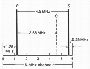
FIGURE 2-6 THE 6-MHZ TELEVISION BROADCAST CHANNEL. P IS PICTURE CARRIER;
S IS SOUND CARRIER: C IS COLOR SUBCARRIER.
Carrier frequencies. Figure 2-6 shows how the different carrier signals fit into the standard 6-MHz channel. The picture carrier frequency labeled P is always 1.25 MHz above the low end of the channel. At the opposite end, the sound carrier frequency labeled S is 0.25 MHz below the high end. This spacing of the carrier frequencies applies for all TV channels in the VHF and UHF bands, whether the broadcast is in color or monochrome.
To apply the standard spacing to actual rf carriers, consider channel 3 as an example.
This channel is 60 to 66 MHz, which is a band of 6 MHz. The picture carrier frequency is 60 + 1.25 = 61.25 MHz. The sound carrier frequency is 66 - 0.25 = 65.75 MHz.
Intercarrier sound. The rf sound carrier can also be figured as 4.5 MHz above the picture carrier because these two frequencies are al ways separated by exactly 4.5 MHz. This difference is important because all television receivers use 4.5 MHz as the frequency for the sound IF signal. The 4.5-MHz signal is called the intercarrier sound signal. The sound signal is made to beat with the picture carrier, to produce the difference frequency always equal to exactly 4.5 MHz. The intercarrier-sound method makes it much easier for the receiver to tune in the sound associated with the picture, especially for the UHF channels. It should be noted that the 4.5-MHz sound is still an FM signal with its original audio modulation.
2-11 Standards of Transmission
Mainly because scanning must be synchronized, the receiver depends on the transmitter for proper operation. This setup makes it necessary to establish standards for the transmitter, so that a receiver will work equally well for all stations.
These have been specified as a list of transmission standards* by the Federal Communications Commission. Several points in the standards are listed here to summarize briefly the main requirements of the television system:
Communications Commission Rules Governing Radio Broadcast Services, Part 3. Subpart E. Rules Governing Television Broadcast Stations. This also gives channel assignments by states and cities.
1. It is standard to scan at uniform velocity in horizontal lines from left to right, progressing from top to bottom of the image, when viewing the scene from the camera position.
2. The number of scanning lines per frame period is 525.
3. The frame repetition rate is 30 per second, and the field repetition rate is 60 per second.
4. The width of the channel assigned to a television broadcast station is 6 MHz. This bandwidth applies to VHF channels and UHF channels, either for monochrome or for color.
5. The associated sound is transmitted as an FM signal. Maximum frequency swing is ± -25 kHz for 100 percent audio modulation.
The sound carrier signal is included in the 6-MHz television channel.
6. The picture carrier is amplitude-modulated by both picture and synchronizing signals.
The two signals have different amplitudes on the AM picture carrier.
7. The color subcarrier has the exact frequency of 3.579545 MHz. (This is rounded off to 3.58 MHz.)
SUMMARY
1. The smallest area of light or shade in the image is a picture element.
2. Picture elements are converted to electric signal by a camera tube at the studio.
This signal becomes the video signal to be broadcast to receivers. The picture tube in the receiver converts the video signal back into visual information.
3. The electron beam scans all the picture elements from left to right in one horizontal line and all the lines in succession from top to bottom. There are 525 lines per picture frame.
4. The complete picture frame is scanned 30 times per second.
5. Blanking means going to black so that retraces cannot be seen.
6. For vertical scanning, the 525 lines in each frame are divided into two fields, each with 262 1/2 lines. The odd lines are scanned separately; then the even lines are scanned. This procedure is interlaced scanning.
7. The vertical scanning frequency is the field rate of 60 Hz.
8. The horizontal scanning frequency is 15,750 Hz.
9. Synchronization is necessary to time the scanning with respect to picture information. The synchronizing pulse frequencies are 15,750 and 60 Hz, respectively, the same as horizontal and vertical scanning frequencies.
10. "Brightness" is the average or overall illumination. On the picture tube screen, brightness depends on high voltage and dc grid bias for the picture tube.
11. "Contrast" is the difference in intensity between black-and-white parts of the picture. The peak-to-peak ac video signal amplitude determines contrast.
12. Detail, resolution, or definition is a measure of how many picture elements can be reproduced. With many fine details, the picture looks sharp and clear.
13. The aspect ratio specifies 4:3 for the ratio of width to height of the frame.
14. A standard commercial television broadcast channel is 6 MHz wide. This includes the AM picture carrier signal 1.25 MHz above the low end of the channel and the FM sound carrier signal 0.25 MHz below the high end. The two carrier frequencies are separated by 4.5 MHz.
15. In color television broadcasting, red, green, and blue video signals corresponding to the picture information are converted into luminance and chrominance signals for transmission in the standard 6-MHz broadcast channel. The luminance signal has the black-and-white picture information; the chrominance signal provides the color.
16. The color subcarrier frequency is 3.58 MHz.
17. The amount of color in the picture, or color intensity, is the color level, chroma level, or saturation. This depends on the amplitude of the modulated chrominance signal.
18. The tint of the color is its hue. The hue depends on the phase angle of the chrominance signal. See Table 2-1.
--------------

TABLE 2-1 PICTURE QUALITIES
QUALITY
Contrast Brightness Resolution Color saturation Hue
PICTURE
Range between black A and white
Background illumination D
Sharpness of details F
Intensity or level A of color
Tint of color P
SIGNAL
Amplitude of ac video signal
Dc bias on picture tube
Frequency response of video signal
Amplitude of 3.58-MHz chroma signal
Phase angle of 3.58-MHz chroma signal
------------------
Self-Examination (Answers at back of guide)
Fill in the missing word or number in the following statements:
1. Picture frames are repeated at the rate of _ per second.
2. The number of scanning lines is per frame.
3. The number of fields is per frame.
4. The number of scanning lines is per field.
5. The number of scanning lines is per second.
6. The horizontal line-scanning frequency is . Hz.
7. The vertical field-scanning frequency is Hz.
8. Video signal amplitude determines the picture quality called _
9. Light is converted to video signal by the tube.
10. Video signal is converted to light by the tube.
11. The bandwidth of a television channel is MHz.
12. The type of modulation on the picture carrier signal is
13. The type of modulation on the sound carrier signal is
14. The assigned band for channel 3 is MHz.
15. The difference between the picture and sound carrier frequencies for channel 3 is MHz.
16. Scanning in the receiver is timed correctly by pulses.
17. Retraces are not visible because of pulses.
18. Black on the picture tube screen results from beam current.
19. The color subcarrier frequency is approximately MHz.
20. The amount of color saturation in the picture depends on the amount of signal.
Essay Questions
1. Why is the television system of transmitting and receiving the picture information called a sequential method?
2. Why is vertical scanning necessary in addition to the horizontal line scanning?
3. Define aspect ratio, contrast, brightness, and resolution.
4. Name the two signals transmitted in color television.
5. How is flicker eliminated by using interlaced scanning?
6. How would the reproduced picture look if it were transmitted with the correct aspect ratio of 4:3, but if on the picture tube screen at the receiver the frame was square?
7. What is the difference between color level and hue?
8. Give two ways in which color and monochrome television broadcasting are compatible.
Problems (Answers to selected problems at back of guide)
1. Give the frequencies included in channels 2, 6, 7, 13, and 14.
2. Calculate the time of one horizontal line for the following examples: (a) frames repeated at 60 Hz with 525 lines per frame (for progressive scanning without interlacing); (b) frames repeated at 25 Hz with 625 lines interlaced per frame (for European standards).
3. A picture has 400 picture elements horizontally and 300 details vertically. What is the total number of details?
4. How long does it take to scan across two elements if 400 are scanned in 50 u-s?
5. Show calculations for the horizontal blanking time of 10.2 u-is as 16 percent of H.