Sawing metal
It might be thought that to cut a piece of metal, it is only necessary to take a few wild swings at the work with a hacksaw whilst the room rings to the screech and shudder of the saw.
This is an excellent way to ruin a perfectly good hacksaw blade, deafen yourself, and produce work of an appallingly low standard. Before using a hacksaw, check:
-- Is the blade inserted the correct way round? (It should cut on the forward stroke) (see FIG. 15).
-- Does it have a complete set of teeth? If any are missing, discard the blade, blades are cheap -- your time is not.
-- Does it have the right number of teeth per inch (TPI)? A saw should have three teeth in contact with the work at all times.
Alternatively, use 18TPI for aluminum, 24TPI for mild steel, 32TPI for harder materials such as stainless steel, and adjust cutting angle if necessary.
-- Is the blade properly tensioned? (The wingnut should be as tight as possible.)

FIG. 15 Detail of standard hacksaw blade showing cutting direction (Blade
cuts when moving from right to left.)
Junior hacksaws are very useful for smaller, more precise work, and the wire frame type is very common. However, proper junior hacksaws have a rigid frame and a screw to tension the blade. Hacksaws are commonly available with pistol grip handles because this makes it easier to apply maximum force, which is important for a full-size hacksaw, but you will find that the more traditional handle allows greater precision (see FIG. 16).

FIG. 16 A junior hacksaw is ideal for more precise work.
Sheet metal
Cutting sheet metal is a problem because a hacksaw blade is insufficiently fine to cut at right angles to the work, so the only way to cut metal sheet is to cut at an extreme angle, and if this means crouching on the floor whilst the work is held vertically in a vice, so be it. A better method is to clamp the work horizontally to the bench, and use a panel saw, which looks like a wood saw, but takes a hacksaw blade (see FIG. 17).
A drop or two of lubricant whilst sawing does wonders for your cutting efficiency but generates a terrible mess and makes it difficult to see your cutting line. The author only saws with lubricant under duress.
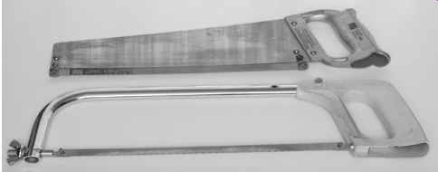
FIG. 17 Standard hacksaw (lower) and panel saw (upper).
Cutting irregular holes
The best way to cut irregular holes is by hand, using a tension file in a standard hacksaw frame or in a coping saw frame (see FIG. 18).
The process starts by drilling a hole in the material that is to be removed.
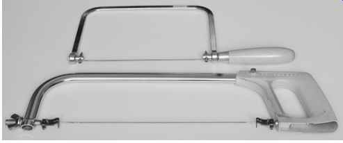
FIG. 18 Tension file fitted to standard hacksaw frame (lower) and coping
saw frame (upper)

FIG. 19 Detail of tension file blade showing cutting direction (right
to left)
The file cuts on the forward stroke, so run the file gently through your fingers to determine the cutting direction (see FIG. 19).
Now fit the file to the handle end of the frame, but pass the file blade through the hole, before fitting it to the other end of the frame and tensioning it. With care, the hole can be cut so accurately that very little remedial filing is needed (see FIG. 20).
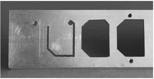
FIG. 20 The sequence of events for cutting an irregular hole. Left to
right: mark out and drill a pilot hole, cut irregular hole with tension file,
tidy hole with file, drill and tap fixing holes
Irritatingly, some connectors require a ''D'' shaped hole, and there's nothing for it but to cut the hole by hand, so it's just as well that a tension file does such a good job (see FIG. 21).
Sometimes the frame of the hacksaw will be unable to reach the proposed hole from any direction.
Hole-cutting files are also available fitted with a handle. To stop them bending, they have to be of a larger diameter than tension files, so you have to remove more material to cut a given distance, making the work harder. Nevertheless, because a frame is not needed, they can reach any part of the work and produce a neat result (see FIG. 22).
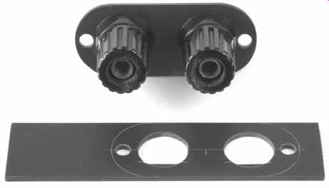
FIG. 21 "D" shaped holes are a nuisance, but are quite easily cut using
a tension file or jeweler’s saw.
A faster alternative is to use an electric jigsaw at low speed with a metal cutting blade having the finest possible teeth. This is not nearly so easy to control and is potentially dangerous. It is also extremely noisy and ear protection is essential. The drumming of the saw on chippings leaves marks on the work unless a piece of thin cardboard is carefully fitted to cover the sole of the saw (see FIG. 23).
As before, a hole is drilled in the material to be removed and the saw blade passed through. Ensure that the teeth of the blade are not touching the edge of the hole, and whilst pressing down firmly, start the saw. When you reach the end of a cut, back the saw off a little before switching off, otherwise the teeth will snatch and the saw will try to jump up from the work, deforming it.
A technique that can be useful when a rectangular hole with radiused corners is needed is to use a chassis punch at each corner, then use a saw to cut straight lines between the punched holes, leaving a rectangle with neatly radiused corners.
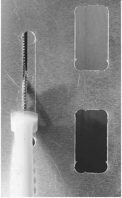
FIG. 22 A single-ended Abrafile can cut holes any distance from the edge
of the chassis
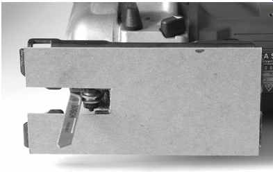
FIG. 23 Fitting a cardboard sole to a jigsaw reduces surface damage when
cutting metal
Making round holes without a punch
Mark out the hole using a scriber, cut it out as carefully as possible, and remove obvious errors with a half-round file.
Take a piece of 160 grade emery cloth and wrap it tightly round a short length of broom handle, and use it to scour a few turns inside the hole as if you were turning a handle.
Rotate the work by 90 degr., and repeat, then twice more, so that the work has been scoured in all four orientations. (The reason for rotating the work is that if all the cutting is done in one orientation, a slightly irregular hole results because you are able to apply slightly more force in one direction than another.) If you now inspect the hole, you will find a significant burr on both sides that needs to be removed carefully using a needle file. Change to 240 grade silicon carbide paper, and repeat the scouring process, and deburr for the final time.
With only a little effort, it is perfectly possible to produce a hole by hand that appears to have been made by a precision boring machine.
Although the author uses this technique mainly for very large holes, it can be used for smaller holes by substituting a round file. Round files will cut using the scouring action, but they clog quickly, so it is best to move them gently back and forth as you scour.
Making holes in perforated sheet
Perforated sheet is wonderful for cooling, and makes subsequent wiring easy, but it is very difficult to make small holes that are not aligned with the existing holes. For this reason, you might choose to allow the geometry of the sheet to determine mounting positions of tubes, etc., rather than enforcing your own geometry. Forget about using a twist drill. The only way to make small holes (~4mm, or so) is to mark them out with a scriber and carefully file them using a needle file. If this sounds tedious, it's because it is, although a single-ended Abrafile in a handle speeds work (see FIG. 24).
A cheat that you can use (that does your tools no good at all, but saves time) is to put a round needle file in power drill, and plunging it gently back and forth, allow this to cut the hole.
Used this way, needle files don't last very long, but you may feel that the cost of a new needle file is an acceptable trade against your time.
Fortunately, larger holes can be marked out and sawn using a tension file or a jeweler’s saw. They're much easier.
Chassis punches still work well on perforated sheet, but it's important to align the cutting edge so that it is supported equally at its cutting tips before tightening the bolt and beginning cutting, otherwise it can pull itself out of alignment.
Deburring can only be done with a needle file, and takes time.
Cutting perforated sheet to size
Hand saws aren't really suitable because they try to follow the path of least resistance - which is usually straight down the middle of the holes, and not necessarily where you want the cut.
A bandsaw is best, and a jigsaw will do, but the essential is a sharp fine blade running quickly.
It's also very difficult to file the cut edge because the file tends to be trapped by the holes. However, 160 grade emery cloth supported on a block of wood 3" by 5" does a superb job very quickly. Top and bottom burrs can be removed using 240 grade silicon carbide paper (again supported by the block), but the vertical burrs at each of the (many) holes have to be removed individually with a needle file.
Despite all these caveats about perforated sheet and its associated metalwork, the end results are well worthwhile.
The traditional chassis
The traditional method of construction was the folded aluminum chassis, and classic designs included beautiful engineering drawings complete with exact dimensions, folding lines, and all holes marked and dimensioned. The author can only assume that there were many more folding machines available in the early 60s, and that all constructors had access to a full sheet metal workshop.
Steel is not suitable for the chassis of tube (valve) amplifiers. Steel is magnetic, and allows leakage flux from transformers to flow through the chassis and induce currents into the pins of the tubes. If a steel chassis is unavoidable, induction into the chassis can be greatly reduced by fitting a non-ferrous gasket between transformers and the chassis; 1.5mm Paxolin is ideal.
Although it is sometimes possible to buy an undrilled folded aluminum chassis, even a small chassis needs to be 1.6mm (16 swg) thick in order to be able to support the weight of the transformers. Although a pre-folded chassis might seem convenient to use, it is always awkward to drill holes in the sides of the chassis, because it is difficult to support the metal whilst it is being drilled.
Making a chassis using extruded aluminum channel and sheet
A far better alternative is to make the chassis out of separate pieces (see FIG. 25).
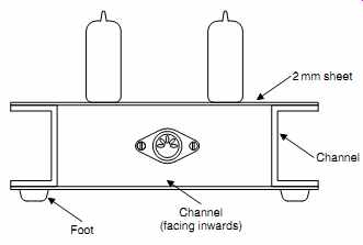
FIG. 25 A very strong chassis can be made from aluminum channel.
The top plate, to which most of the components will be fitted, is made of 2mm aluminum, which is readily available either as off-cuts from an aluminum stockholder or from one of the electronic factors. Whilst it is tempting to use even thicker metal, many of the holes will be cut using chassis punches that can be damaged by thicker metal. Additionally, most tube (valve) holders were designed for 1.6mm chassis, and whilst they can tolerate 2mm, clearances become problematic if the plate is thicker.
The front, back, and sides are made from extruded aluminum channel cut to length. The sides have the channel facing out, thus providing convenient handles with which to lift the chassis, with the front and back fitting into the remaining space between the sides. The whole construction is then fastened with engineering screws and nuts. This form of construction has many advantages over the folded chassis:
-- The chassis can easily be made to any convenient size using hand tools. It need not even be rectangular!
-- Cutting holes in the chassis is now easy, because each surface can be properly supported whilst it is being worked upon.
-- If modifications are required later (not uncommon), individual parts can be replaced if necessary.
-- Aluminum channel tends to be quite thick (3 or 6mm), making it a good heatsink, and threaded holes may be tapped into it, which is often convenient.
-- If access is needed at one edge, that piece of channel can be temporarily removed.
-- Looking at the bottom of the chassis, the channels are rigid load-bearing members to which feet and the safety cover plate can be easily fixed (which should ideally be perforated, to allow a cooling air flow). Fitting a cover plate to the bottom of a folded chassis is usually rather more difficult.
There are only two minor disadvantages. Firstly, the total top area is a little larger than the folded aluminum chassis, because some space is wasted at the sides by the outward facing channel. Secondly, for safety, each separate piece of aluminum should be reliably earth-bonded to the top plate with star washers at one or more of the fixing points.
Corner pillars
Larger chassis are less rigid, yet they are usually called upon to support more weight. Although a chassis can be constructed by simply screwing channels to the top plate, a huge increase in rigidity can be gained by fitting 16mm square section corner pillars so that the channels form a self-supporting rigid picture frame onto which the top plate, or plates, are screwed.
The author faces each end of the pillars in his lathe -- which allows the pillars to be made a snug fit inside the channel.
Assuming you can gain access to a lathe, the sequence of events for machining a pillar to length with maximum precision and minimum tears is as follows:
-- Carefully measure the internal width of the channel at the corners - not the open ends. The reason for this is that channel is rarely square (usually as a result of being clamped in a vice whilst you cut it to length) (see FIG. 26).
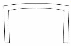
FIG. 26 Clamping channel for sawing tends to deform it slightly.
-- Cut four lengths of 16mm square bar to be 1-2mm longer than your measured internal dimension.
-- Take a pillar and face both ends in the lathe with minimum wastage. (Centering is not important.)
-- Remove the pillar from the lathe, and measure its length with calipers.
-- Subtract the required length from the measured length to find out by how much it is oversize. If you use digital calipers (easiest), you will probably obtain fractionally different answers depending on where you measure -- indicating that the faces are not perfectly square. This doesn't matter, it's still far better than can be achieved by hand.
-- Add 0.1mm to the previous answer. In theory, this means that the finished pillar will fit into the channel with a 0.1mm gap. In practice, it means that the pillar is guaranteed to fit in the channel, and because the channel is usually slightly distorted, it will probably grip the pillar snugly.
-- Put the pillar back in the lathe, engage power, and gently ease the lathe tool up to the face until it just begins to cut.
-- If you now set the dial on the lathe slide to zero, its graduations can now guide the removal of the required amount of material quickly and precisely.
Fitting the pillars
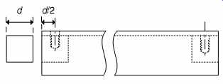
FIG. 27 Positioning drill holes for pillars inside channel
The neatest way of securing the pillars to the channels is with a pair of M5 screws from each channel into tapped holes in each pillar. This is done as follows:
-- Two of your channels will have pillars inside them. Decide which these channels are, and drill M5 clearance holes at each end (5mm, or perhaps 5.1mm to allow adjustment on assembly) (see FIG. 27).
-- Gently ease a pillar into the channel. You may need to use a finger and thumb to spread the channel slightly to ease it in.
Provided it is slightly in, the pillar can be gently tapped with a soft hammer until it is perfectly flush with the end of the channel, or press the two together on a flat surface. Running a finger over the join checks correct alignment far better than peering at it.
-- Without disturbing alignment, use a small G-clamp to hold the pillar securely in place without obscuring the 5mm holes.
-- You can now mark through the 5mm holes to determine where the pillar should be drilled and tapped. The ideal way of marking through is to make a dedicated center-punch out of a piece of scrap metal having a 5mm diameter stub faced by a poorly aligned tool so that a slight dimple is left at the center. The punch can then be dropped through each hole in the channel and tapped lightly with a hammer to leave a precisely positioned dimple ready for drilling (see FIG. 28).
-- It is vital to scribe an identifying number onto each pillar and its corresponding position so that you know both where it belongs and its orientation. (Methylated spirits and/or finger grease removes pen or pencil.)
-- Remove the pillar, use a 3mm center drill to start each hole, then drill a 4.3mm (M5 tapping size) hole to a depth of 10-12mm, and tap it M5.
-- Slide the pillars into their correct positions in the channels, and secure them withM5 screws. Their alignment will be near perfect, and a tiny amount of nudging will achieve perfection.
You now have a pair of channels with pillars secured at each end, and want to fit these to your other two channels to form the frame. It is very easy to make a mistake at this point, so be careful.
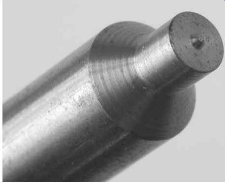
FIG. 28 A 5mm center-punch allows perfect marking out and drilling
-- Looking down onto the finished frame, theM5 clearance holes must be offset from the end of the channel by half the pillar cross-section, plus the channel thickness (see FIG. 29).
-- Having drilled the M5 clearance holes, lay out the entire frame on a clean flat surface, and use small G-clamps to secure it at the corners without obscuring the M5 holes.
Check alignment carefully and adjust as necessary.
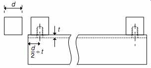
FIG. 29 The pillars are offset by the thickness of the adjacent channel
so the 5mm holes must also be offset.
-- Mark through the M5 holes to the pillars, ideally using the dedicated M5 center-punch.
-- Remove the clamps and unscrew the pillars from the first pair of channels.
-- Drill and tap the pillars.
You can now proudly assemble a perfectly aligned picture frame.
Fitting the top plate
The top plate inevitably needs lots of holes for all the tubes and subsidiary components. It also needs to be secured to the picture frame. The easiest way to do this is to drill securing holes in the top plate, then clamp it to the picture frame with a couple of G-clamps and punch through to mark where holes need to be drilled in the channel. Rather than use nuts and screws, the author prefers to tap the channel, but you might have a different opinion.
Fitting carpet-piercing spikes
The corner pillars provide an ideal depth of material to be tapped M6 and fitted with loudspeaker carpet-piercing spikes. The spikes might not confer any sonic advantage, but they certainly allow a heavy amplifier to sit on a carpet without leaving a mark.
The obvious way of drilling the required axial hole in the pillars is in the lathe during facing, but it is fiddly to center square stock perfectly (even in a four-jaw chuck), so drilling the channel so that it aligns correctly with the (blind) hole becomes even more difficult. The author has found it easier to face the pillars without worrying about centering, then offer the assembled frame up to the drill and drill theM6 tapping holes (5.1mm) straight through the channels and into the pillars. Because two channels at right angles are resting on the base of the drill stand, this ensures that the drilled hole is square.
You could tap M6 straight through the channel and into the pillars, but you might prefer to remove the pillars for tap ping, and drill the channel M6 clearance. This reduces the amount of thread supporting the finished amplifier, but because the clearance hole guides the spike into the thread, it makes it slightly easier when fitting a spike blindly from underneath.
If you don't have access to a lathe...
Right-angled brackets cut by hand from 25mm extruded aluminum angle make perfectly acceptable corner braces. The channel can be drilled and tapped to take carpet-piercing spikes, but be aware that because the channel only allows 3mm depth of thread as opposed to 10mm, this not quite as strong as tapping into pillars.
Finishing
Aluminum can be spray painted, but paint tends not to stick very well to aluminum, and tends to chip off unless etching primer is used. Buying aerosol cans of car primer and top coat is quite expensive, and the fumes are most unhealthy. Nevertheless, this is one way of finishing the chassis.
A better method, but one that requires rather more planning, is to have the chassis anodized by a professional anodizer.
Note that only aluminum can be handed to an anodizer; no foreign substances whatsoever are allowed. Surprisingly, this is actually quite cheap, because the pieces that you will hand over will be very small compared to the main batch that is being anodized. It may mean that you need to wait until a batch of your chosen color is to be anodized, but the finished result will be far superior, provided that you have prepared the work properly.
An awkward problem with anodizing is that it slightly increases the size of your work, and reduces the size of holes. If you have done a really nice piece of metalwork that snugs together beautifully, it is somewhat disconcerting to discover that it no longer fits. Commercial manufacturers use their prototypes to discover the amount by which their work should be undersize before anodizing . . .
Both painting and anodizing show up every imperfection of the underlying surface, so the surface cannot be too well prepared.
A ''brushed'' finish can be obtained using reducing grades of silicon carbide (often known as ''wet and dry'') rubbed along one direction only. If the final stage is lubricated with soap and water, a very smooth finish can be obtained. Alternatively, soap-filled wire wool scouring pads soaked in hot water can be very effective.
It is far better to begin with a good surface, so most stock holders keep aluminum that has one face protected with a plastic film. Keep the film on for as long as possible, and do not allow objects to fall on the sheet; aluminum is soft and easily marked. If using a scriber, keep your construction lines to a minimum, and score lightly with a sharp scriber -- the marks that a blunt scriber makes are much more difficult to remove.
Whether you paint or anodize your chassis, make sure that you really have drilled all the holes you need. Drilling holes after wards is invariably messy and easily spoils your finish.
