BY HERBERT ELKIN [Loral Electronic Systems, Yonkers, NY. ]
When your line voltage nosedives, this circuit gives a 6-volt boost.
DO YOUR lights go dim, does your TV picture shrink and lose brightness, or are your AC appliances acting as though they're just plain tired? You may be living in an area subject to "brownouts" (low power-line voltage), and the solution to your troubles could well be some form of voltage regulation.
The automatic line voltage regulator described in this article will automatically raise power-line voltage by about six volts whenever it drops below a preset level. When the line voltage returns to normal, the compensation automatically drops out. (See Fig. 1.)
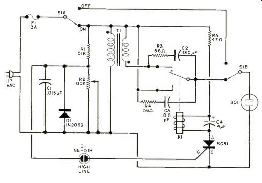
Fig. 1. When line voltage drops, K1 adds the 6.3-V secondary of T 1
in series with the line to raise the output at S01.
PARTS LIST
C1, C2, C3--0.015-µF, 400-volt ceramic capacitor
C4-- 4 uF, 250-volt electrolytic
D1--1N2069, 1-ampere, 200-PIV rectifier
F1--3-ampere, slow-blow fuse with holder
I1--NE-51H neon lamp assembly (Dialco 95-0463-0931-211 or similar)
K1--2pdt, 48-volt, 2500-ohm relay (Sigma 62R2-48DC-SCO or similar)
R1--51,000-ohm, 1/2-W, 10% resistor
R3, R4--56-ohm, 1/2-W, 10% resistor
R5--47-ohm, 1/2-W, 10% resistor
R2-100,000-ohm, multi-turn pot.
S1--2pdt switch
SCR1--4-ampere, 200-Ply silicon controlled rectifier
T1--6.3-V 3-A, filament transformer
Misc.-Ac receptacle (S01), terminal strip, suitable enclosure, spacers, mounting hardware, etc.

Fig. 2. Waveform at (A) is line voltage; (B) is voltage across C1; (D)
is SCR conduction angle. ------ Interior photo of the prototype
regulator. Components can be mounted on pc or perf board.
Circuit Operation. Filament transformer T1 is connected with its 6.3-volt secondary in series with the primary so that the two voltages add. Relay KI taps an output from the primary alone or from the combined windings. The remainder of the circuit senses the output voltage and sets (or resets) KI to switch the extra winding in or out as needed.
As can be seen from Fig. 1 and the waveforms of Fig. 2, capacitor C1 follows the swings of the fraction of the power-line voltage developed across the R2 portion of voltage divider R1-R2.
Potentiometer R2 is adjusted so that the peak voltage across C1 just reaches the firing level of neon lamp II when the voltage across R1-R2 reaches the level where automatic compensation is not required. The neon lamp breaks down and applies a positive pulse to the gate of SCR1, causing the SCR to turn on and hold relay K1 in the position that directs the normal line voltage to the output.
The SCR, then turns off when the power-line voltage passes through zero. The neon lamp fires on each positive half cycle, allowing its glow to be used as a "normal" line voltage indication. During the negative half cycles, diode D1 clamps C1 to circuit ground, thus keeping the neon lamp "off" and preventing the negative pulse from being applied to the SCR gate.
Because its drive switches on and off at power-line frequency, relay K1 would normally "chatter". Capacitor C4, connected across the relay coil, prevents this problem as it charges when the SCR fires to provide both filtering (due to rectification of the ac voltage by SCR1), and relay-coil holding current when the SCR is off.
The networks consisting of R3-C2 and R4-C3 form arc-suppression circuits to minimize relay contact pitting, while R5 limits SCR surge current to a safe value. Using the parts shown in Fig. 1, appliances drawing up to 350 VA can be controlled. For higher power, a larger transformer and a relay with heavier contacts can be used. Make sure that fuse F1 is a slow-blow type to accommodate any turn-on surge currents. To bypass the compensation circuit, switch S1 can be set to OFF. Construction. With the exception of transformer T1, output socket S01, neon lamp assembly L1, and on/off switch S1, all components can be mounted on a small pc board-or a perf board, using point-to-point wiring. The board can be mounted in any type of enclosure that can accommodate all of the components. The line cord exits through a grommeted hole.
A terminal strip with nongrounded lugs must be used for the transformer leads and ac power connections. If a metal enclosure is used, it is important that it be isolated from both sides of the power line to prevent a shock hazard.
The windings of T1 can be phased using the setup shown in Fig. 3. Temporarily connect one secondary lead to one side of the primary as shown. Very carefully (to avoid shock), measure and note the voltage appearing across the transformer primary alone. This is the line voltage. Then measure the voltage across the combined primary/secondary and note that it is 6.3 volts higher. If the voltage indication is less than the noted line voltage, phasing is incorrect. Exchange the two secondary leads and repeat the above test. When the combined voltage is higher than the line voltage, you know that the transformer leads are properly phased.
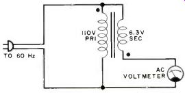
Fig. 3. Meter should read 6.3 V above line with transformer connected
as shown.
Calibration. To adjust the low-voltage trip point, a source of variable line voltage is required. (A Variac or similar device will do.) Adjust the power-line input for 110 volts--or whatever voltage you wish the relay to trip at--and connect an AC voltmeter across the contacts of SO1. Vary potentiometer R2 until neon lamp L1 glows and note that as this happens the relay is activated, which means that the voltage is not boosted, and the ac voltmeter across SO1 registers 110 volts.
Carefully rotate R2 until the neon lamp just extinguishes and the relay de-energizes. The ac voltmeter across SO1 should move up to approximately 116.3 volts. Slowly increase the input voltage level until the neon lamp lights and note that the ac voltmeter indicates about 112 volts. Set the trip point wherever you want it to occur.
In Conclusion. This project represents a simple, inexpensive way to provide some compensation for low power-line voltage. Its regulation is somewhat coarse, but is sufficient for most home appliances. Note that, since relay KI interrupts power briefly while switching in the booster winding, the circuit may not be suitable for use with sensitive devices such as computers or digital clocks.
Source: Computers and Electronics--Experimenter's Handbook (1984)
Also see:
Cancel Rumble With This Bass-Summing Amplifier
How Ordinary Oscilloscopes Can Display Multi-Channel Logic Signals
A Low-Cost Emergency Broadcast System Monitor