Thomas Edison was one of the first to develop a way to capture and store sound. Among his many inventions was the phonograph, which he completed in the evening of December 6, 1877. This mechanical contraption transcribed the vibrations of sound into a cylinder made of metal foil. By moving a needle through the grooves made during recording, the sound could be played back. The first '‘record" was born.
Almost 10 years later, another invent or, by the name of Emile Berliner, designed his version of the phonograph. He called it the gramophone, and it used flat pancake-like records. From both the original Edison phonograph, and the Berliner gramophone, the record player--as we know it today was born.
The sound quality of the early Edison and Berliner phonographs was scratchy and poor. Edison's original test recording of " Mary Had a Little Lamb," which he made on his prot otype phonograph, survives today. It sounds the same as it did over a hundred years ago--bad.
Advancements in audio playback have been scarce since Edison and Berliner’s time. Sure, the record player was electrified in 1925, with the introduction of the Brunswick Panatrope, and the quality got a little better because of it. Magnetic tape recorders using plastic tape were perfected during World War II, as part of the German war effort. It took years for tape recorders to reach the home, and the sound they reproduce still isn't all that good.
Audio advancements have been slow in coming, but in 1980 that trend changed. That was the year the compact disc was officially Introduced. The compact disc (CD) is unlike any other kind of au dio medium ever seen or heard. As shown in Fig. 1-1, the CD looks like a silverised 45-RPM record, but it holds over 74 minutes of crystal clear music.
The CD is played on a compact disc player. It uses digital computer technology to play back music with incredible high fidelity. With little exception , music from a compact disc player is an exact aural mirror image of the original performance. Because of the way the compact disc works, you can't hear scratches or tape hiss like you can with records and tape recorders.
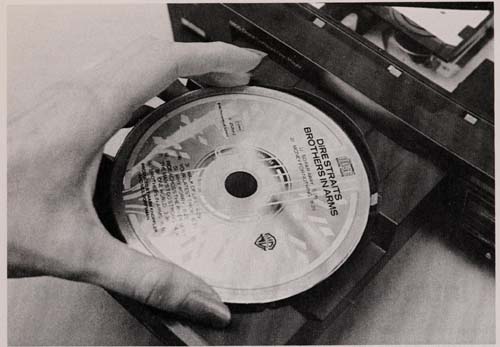
Fig. 1-1. The compact disc is the most revolutionary sound storage and
reproduction System to come out since Edison invented the phonograph.
Let’s take a close look at the technology behind compact discs, and find out why they reproduce sound as well as they do. We’ll investigate how the discs are recorded, made, and played back on a CD player. This section is devoted to the science and technology behind the compact disc. Section 2 discusses in detail how compact disc players retrieve the audio from the disc and process it for our ears to enjoy.
THE COMPACT DISC: AN INTERNATIONAL STANDARD
The compact disc was jointly conceived by two electronics giants: Sony, in Japan, and Philips, in the Netherlands (audio buffs will remember that it was Philips that also invented the common audio cassette tape cartridge that is in wide use today).
Separately, the two companies had been working for years on a way to digitally encode audio information and play it back on an inexpensive home player. Fortunately, they decided to join forces and establish a worldwide digital audio standard.
This standard covers many things-including the way the audio is encoded on the disc, the size of the disc, the speed of the disc during playback, and other factors. See Table 1-1 for more complete specifications of the CD standard.

Table 1-1. Compact Disc Specifications (coming soon; see Wikipedia in the
meantime)
Philips and Sony license the CD technology to other manufacturers, who follow the standard to the letter (or should at any rate). As a result, any compact disc you buy will play on any compact disc player. If you’re into computers, you are well aware of the incompatibility problems between different computer brands (or even models made by the same company). Not so with the compact disc.
A CLOSER LOOK AT THE COMPACT DISC
Physically, the CD doesn't look like much, but appearances can be misleading. The disc (Fig. 1-2) is 12 centimeters in size, or about 4.7 inches. It has a thickness of 1.2mm, and the hole in the center has a diameter of 15mm. The disc itself is composed of a very thin piece of stamped aluminum en cased in plastic. The discs sold today have music on one side, but there is no technical reason why a CD could not be made to hold music on two sides.
The original design of the compact disc specifies that the maximum total playing time per side is 60 minutes. Theoretically, this can be increased to 80 minutes, which means that only a single side of a CD would be sufficient for Beethoven's entire 9th Symphony (with applause). A total playing time of about 74 minutes is the current practical limit for compact discs.
The compact disc is capable of containing either 2-channel or 4-channel audio. Four-channel audio consumes twice as much disc space because the disc turns twice as fast. The maximum playing time with 4-channel audio is 37 minutes.
Compact discs can hold up to 99 music selec&tions, or songs, as long as the total running time forthe selections do not exceed the maximum ca pacity of the disc. Each selection can be Further divided into index points. When the disc is created, index points can be placed at the beginning bar or other important place in the music.
Information on a compact disc is composed of very small ''pits," originally et ched into a master by a laser. The pits spiral from the inside of the disc to the outside. stretched out, the spiral of pits would go on for 3 miles. The flat areas between each pit are called lands. Together, the pits and lands correspond to a sequence of digital data.
The spiral path that the pits and lands take around the disc is the track. Track is a better word than groove. There is no continuous groove on a compact disc, as there is with a record. The term track is also often used to denote a music selection.
In this guide, to avoid confusion, we will refer to the track of pits and lands on the disc as the data track or information track. Individual audio selections will be referred to as music tracks.
Refer to Fig. 1-3. The pits on the CD are 0.5 micrometers (um) wide. The tracks are spaced 1.6 / tm apart. It’s hard to imagine anything this small, but consider this: You can pack 20,000 compact disc tracks to the inch, 60 tracks in the groove of an LP record, 30 tracks on the strand of hair, and about 750 crammed inside a lowercase o! During playback, the disc rotates clockwise (when viewed from the top) at speeds that range from 200 to 500 rpm. Because the tracks are longer, the rotation of the disc slows when information from the outer edge is retrieved. More pits can be crammed into one rotation, as shown in Fig. 1-4, and the disc slows down to take advantage of the extra real estate. This technique is called const ant linear velocity, or CLV, and helps increase the play-ing time of the CD.
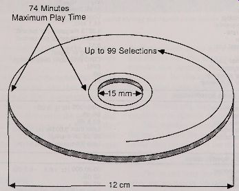
Fig. 1-2. CDs hold up to 74 minutes of high fidelity stereo music on one
side of the disc.
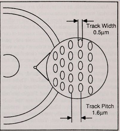
Fig. 1-3. The surface of the CD is covered with billions of micro-sized
pits.
AUDIO ENCODING
In a record player, sound is reproduced by a needle traveling in a narrow, bumpy groove, as il lust rated in Fig. 1-5. The bumps make the needle vibrate, and the vibrations are transmitted mechanically to a cartridge. The cartridge contains a transducer made of magnetic or crystal material, which translates the mechanical fluctuations of the needie into electrical impulses.
Sound is retrieved from a compact disc in an entirely different manner, as diagrammed in Fig. 1-6. Section 2 goes into detail on exactly how a compact disc player works, but here is the general process.
A laser built into the player emits a pencil-thin beam of infrared light that strikes against the pits and lands on the disc. When the beam reflects off the flat lands, most of the light is reflected back into a photo Detector. When the beam reflects off the pits, less light is reflected into the photoDetector.
The result, as seen by the photodetector, is a sequence of very short on-off flashes of light. A circuit inside the player takes the on-off flashes and converts the data from digital format to analog format. Once in analog form, the signal is routed to an amplifier for listening. Let’s backtrack a bit and investigate how the music got on the disc in digital format in the first place.
Fig. 1-4. Constant linear velocity packs more music onto a disc.
THE DIGITAL ENCODING PROCESS
Analog signals, as you probably are aware, are electrical waves that continuously change. There are an infinite number of steps between the smallest and largest analog signals. Imagine a light bulb on a dimmer circuit. Apply only a small amount of current to the bulb by turning the dimmer only part way, and the light turns on. But it doesn’t glow very brightly.Keep turning the dimmer control and the current increases, until the light glows with full brightness.
Digital signals, on the other hand, are comprised of only two states--on and off. These two states are commonly referred to as 0 and 1, or low and high, respectively. The 0 and 1 digits are collectively referred to as bits, and are the only numerals in the entire binary counting System.
Returning to the light bulb, you no longer can dial in any brightness you want. You have only two choices: off and on.
Damper Disc stylus Piezoelectric Converter
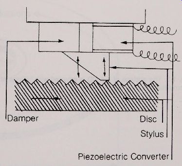
Fig. 1-5. The mechanical stylus of a record player.
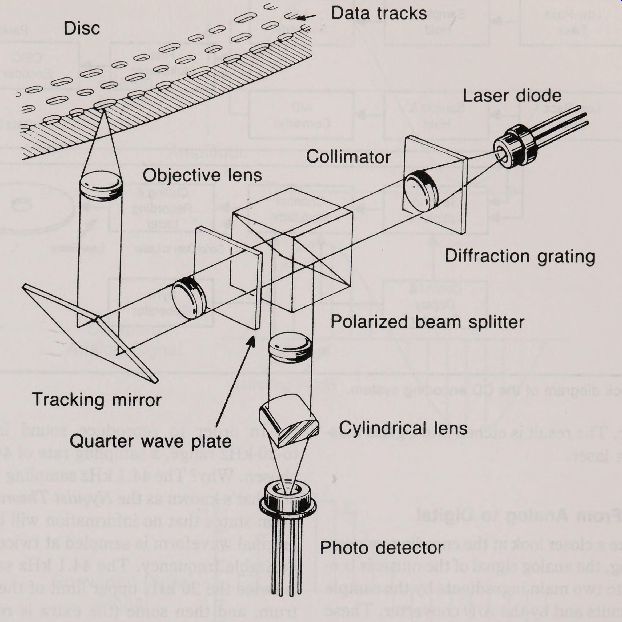
Fig. 1-6. The optical components of a typical compact disc player, and
the method of "reading" a disc.
At first glance, it would seem that digital signals are very restrictive. Actually, you can string together a number of binary 1’s and 0’s and, with a translation circuit, you can turn those numbers into an analog signal. You can also go the other way around. You can take an analog signal and convert it into a digital number. This is exactly what happens in the compact disc audio-encoding process.
Analog-to-Digital Conversion
Before music is recorded on the compact disc, it is translated to its digital equivalent. The entire process is shown in block diagram form in Fig. 1-7.
The conversion first begins with the low-pass filter, sample and hold circuits, and A/D converter.
There are two sets of these circuits, one each for the right and left channels. The low-pass filter blocks frequencies above 20 kHz, the cut off range specified in the CD standard. The sample and hold and D/A converter circuits examine the music and convert it to its digital equivalent. (Not surprisingly, a digital-to-analog converter, with another sample/ hold circuit, is located in the CD player.) The digital data from the two channels is multiplexed (mixed), and then processed with error correction data, control and display information, and synchronization data. Finally, it is modulated in a unique binary format specifically designed for compact disc. The result is etched into a glass master disc by a laser.
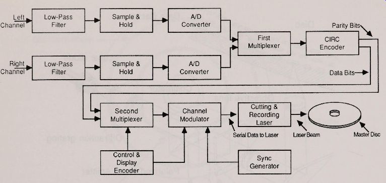
Fig. 1-7. A block diagram of the CD encoding System.
Let’s take a closer look at the encoding process.
After filtering, the analog signal of the music is broken down into two main ingredients by the sample and hold circuits and by the A/D converter. These The Road From Analog to Digital two ingredients are time and amplitude.
The music changes over time, and the A/D converter examines the sound at regular, pre-determined intervals. This process is known as sampling. The audio signal is sampled at 44.1 thousand cycles per second, or more commonly expressed as 44.1 kHz. Therefore, the smallest piece of music is only 1/ 44,100 of a second long.
The sampling process examines discrete moments in the audio signal. Does this mean that periods between these sampling points are missing, and the music in between is lost ? No. The reason lies in the fact that the compact-disc System is designed to deliver sound over the entire human hearing range of approximately 5 Hz to 20 kHz. Neither humans-and hence CD players-care much about sound that occurs above 20 kHz.
In order to reproduce sound in the 5-Hz to-20-kHz range, a sampling rate of 44.1 kHz was chosen. Why? The 44.1 kHz sampling rate is based on what’s known as the Nyquist Theorem. This theorem states that no information will be lost if the original waveform is sampled at twice the highest desirable frequency. The 44.1 kHz sampling rate is twice the 20 kHz upper limit of the audio spectrum, and then some (the extra is reserved as a buffer ). As a result, every possible frequency in the range of human hearing is captured in the sampling process.
As mentioned earlier, the A/D converter breaks the audio signal into two ingredients. We have discussed time. Now consider the other ingredient, amplitude. At any given moment, sound has a certain amplitude, or volume, and this volume is translated in the digital process as well. The conversion of volume into digital values is called quantization.
The word may sound complex, but it’s really a simple concept.
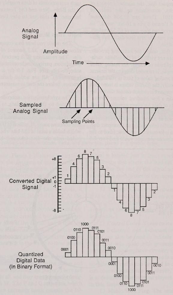
Fig. 1-8. Converting analog sound into digital signals.
Quantization determines the quantity--in this case volume--of any given sampling period.
Now refer to Fig. 1-8. For every sampling period, which is time, the A/D converter senses its relative volume level, which is amplitude. The converter assigns a digital number to each sampling point. For a compact disc, the number consists of 16 binary digits, something on the order of 1000110101110101. There are 65,536 different combinations of 1’s and 0's in a 16-bit '' word," so any sampling period can have any of 65,536 values.
Figure 1-8 shows just the first four digits in a simplified 4-bit system.
You'll note that, unlike the sampling process, quantization does not yield all of the infinite variations in the amplitude of sound. An analog value of 99.2, for example, is rounded down to the nearest digit, or 99. An analog value of 99.6 is rounded up to 100. Realistically, the 65,536 values is more than enough for the human ear, which cannot discern between more than a few hundred volume levels.
With 16 bits of data for every sampling period, that makes for 705,600 bits of audio information in just one second of music! As you'll see, there is more than just audio information on a compact disc.
Given this extra information, and a disc filled to the brim with 74 minutes of music, you'd find over 6.5 billion bits of digital data. In more concrete terms, such vast amounts of data roughly equals 10 copies of the Bible-New and Old Testaments combined! Imagine. All that just to play Benny Goodman.
More Than Music Bits
The music you hear on a compact disc actually accounts for only 32.7 percent of the bits on the disc. The remaining 67.3 percent is composed of modulation, parity, synchronization, merging, and subcode bits (see Fig. 1-9 for a more complete breakdown). All are added during the encoding process, before the disc is mastered and copies are made.
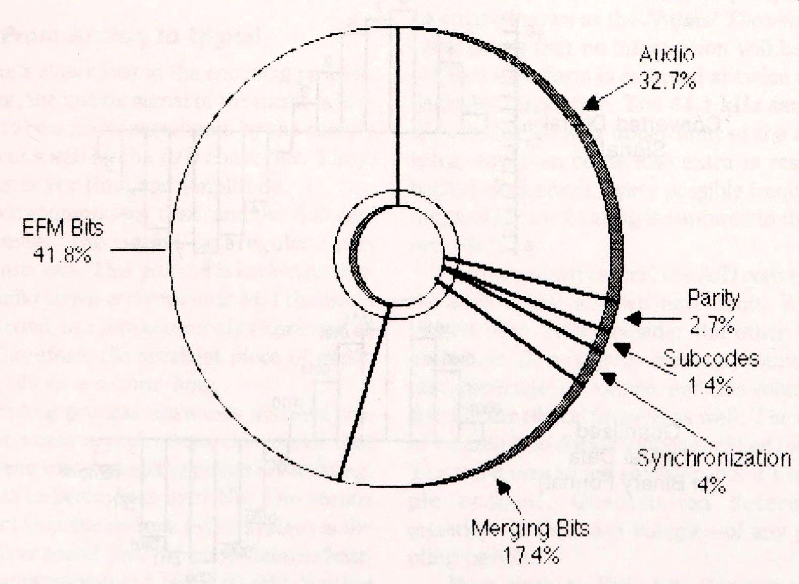
Fig. 1-9. The composition of the CD; audio bits account for only 32.7
percent of the data on the disc
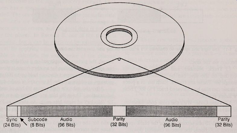
Fig. 1-10. Frames consists of sync, subcode, audio, and parity bits, placed
in a specific order.
The synchronization, subcode, and parity bits are added to the music data to create discrete frames. The frame is the smallest block of data that the CD player manipulates at one time, and a filled disc contains some 34 million of them. Each frame, which holds a total of 588 bits when eventually en coded onto the disc (channel) bits, corresponds in time to 136 u sec. Figure 1-10 shows a pictorial representation of the contents of each frame.
In some technical CD literature, the bits in the frame are sometimes referred to as symbols. A symbol is simply a set of eight bits. So, if you read that a certain piece of data contains four symbols, it means it is made up of 32 bits (8x4 = 32). At the start of the frame is a pattern of 27 synchronization bits, specifically 100000000001000000000010.
This series of uniquely ar ranged bits does not occur in any other part of the frame, and it tells the player that a new frame has begun. The synchronization bits are necessary so that the player can assign all of the other bits in the frame to their proper functions.
The following eight bits comprise subcode data, which provide useful information to the player and possibly the person operating the player. There are eight subcodes in all, and they are technically designated P through W.
The P and Q subcodes, which are the only ones currently used, contain the following information:
Lead-in and Lead-Out Signals. The lead-in signal is located just in front of where the signal’ea on the disc starts; the lead-out signal appears right after the end of the signal area. These two
signals are used to control the movement of the optical pickup in the player.
Table of Contents. Written in the lead-in area is the time information on control codes, including the start time of each selection on the disc as well as the total number and playing time of selections.
Control Codes. These codes distinguish between 2-channel and 4-channel recording. The codes can also be used to indicate if a particular recording was made with preemphasis. In most players, the preemphasis circuitry is automatically switched on when pre-emphasis is required.
Additionally, the codes can be used to change the circuit connections inside the player, if the machine is so designed. Presently, no players are engineered in this fashion.
Music Start Flag. The music start flag is provided in the blank space between selections. By counting this flag, the player can locate any desired
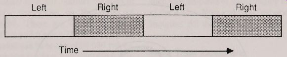
Fig. 1-11. The right and left stereo channels are encoded on the disc
one after the other.
selection on the disc.
Track Number and Index. Selections recorded on the disc can be numbered from 1 through 99. These are tracks. Each bar in a piece of music can also be addressed from 1 to 99. These are index points.
Time Code. With the time code function, the player can process and display the time lapse from the beginning of each selection in minutes, seconds, and 1/75 of a second. During the blank space between selections, the time is counted down.
The remaining subcodes aren't used in most discs and players, but can hold a variety of information. A number of CD manufacturers currently make players with separate data outputs for processing the extra six bits of subcode data. More players with this feature are on the way. This subcode data can include things such as album liner notes, sheet music, color photographs, and more.
An entire video picture can be created by collecting only five seconds worth of subcode data (that’s the equivalent of approximately 20,000 to 30,000 audio frames). After the data has been collected, the picture is displayed on a suitable monitor, and the information for another frame is slowly gathered. One compact disc can hold up to 700 still pictures, in addition to the 74 minutes of audio data.
After the subcode data comes 96 bits of audio information. These 96 bits are broken down into 12 “blocks" of eight bits each. As shown in Fig. 1-11, the first eight bits comprise the audio for the left stereo channel, the next eight bits comprise the audio forthe right stereo channel, and so on. Be cause the stereo information is encoded individually, one right after the other, channel separation on CD players is theoretically 90 dB or better. Unlike turntables, cassette decks, and FM tuners, you’ll hardly ever hear crosstalk between the two stereo channels.
The compact disc System includes a sophisticated error-correction System that uses parity checking. Simply stated, parity data is mathematical totals" that the player uses to determine if any music information has been lost. Should information indeed be missing, the parity data is used by the player to reconstruct the loss.
You can more readily understand how parity ...
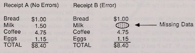
Fig. 1-12. Parity data reconstructs lost information.
... works by refer ring to Fig. 1-12. Imagine the music recorded on the disc as grocery receipts. Each item has a specified price, and the prices are totaled. The prices themselves are like the audio data the totals are like the parity data. In Receipt A there are no errors, and the total data is not used by the player. In Receipt B, one of the prices is missing, but it can be retrieved by examining the total. By applying some simple arithmetic, it’s possible to calculate the exact price of the missing value (in this case $1.50).
Two sets of parity data are added to each frame of audio. The first parity set, called P (not to be confused with the P subcode), is used to Detect and correct errors due to lost data.The other set of parity bits, labeled Q, allows a player to determine whether an error has occured. The Q parity bits serve the same general purpose as the parity bits used in computer telecommunications.
Interleaving
The use of parity bits is only one of the error correction schemes used in the compact disc system, the other is interleaving. This technique is based on the Cross-Interleave Reed-Solomon Code or CIRC, and is performed to the entire frame of synchronization, subcode, audio, and parity information.
With CIRC, the bits of audio information are scattered among several different frames-sor to like shuffling a deck of cards. However, the scattering is not random but follows a set of strict rules Circuitry in the player knows how to decode the interleaved data and place the bits back into their proper sequence. With interleaving throughou many frames, there is much less chance of losing a large chunk of data.
Figure 1-13 illustrates the interleaving process and how errors can be more readily concealed Without interleaving, a dropout (from a smudge speck of dirt, scratch, etc.) might cause a very large contiguous piece of audio data to be lost. The re sult of this lost data is an audible error--a click or pop-during playback. With interleaving, the data is jumbled so that a dropout affects noncontiguous bits of encoded audio data. When re-interleaved the player can better approximate, through a process known as interpolation, the smaller por tions of lost information. The result is that most errors due to data dropouts are completely concealed.
Encoding the Data
With the synchronization, subcode, audio, and parity data assembled in frames-and interleaved to minimize audio errors in playback-it is modu lated to create a unique 14-bit code (Fig, 1-14). despite the addition of more bits, this 14-bit code actually saves space on the compact disc. Without EFM, the compact disc would hold roughly 25 percent less music.
The 14-bit code is called EFM, which stands for Eight-to-Fourteen Modulation. With it, every eight bits offrame data is converted to 14 brand new bits.
Because of the way the pits and lands on the disc represent binary Ts and 0's, three merging bits are added between each set of 14 EFM bits. With the merging bits added, there is never an instance when there is more than one binary 1 for every three bits of data. Similar, the EFM process assures that there is a binary 1 for at least every 11 bits.
This is also required because of the way the data is et ched on the disc by the laser.
During playback of a disc, the CD player strips off the merging bits, demodulates the data, and separates the subcode, data, and error correction information using the synchronization bits. Once separated, the sync bits are tossed aside. Table 1-2 compares data bits (used in the actual reprocessing of the audio signal) and the channel bits, which comprise the data encoded on the disc.
MAKING THE DISC
With the audio data fully encoded, it is finally ready to be made into a compact disc (whew!).
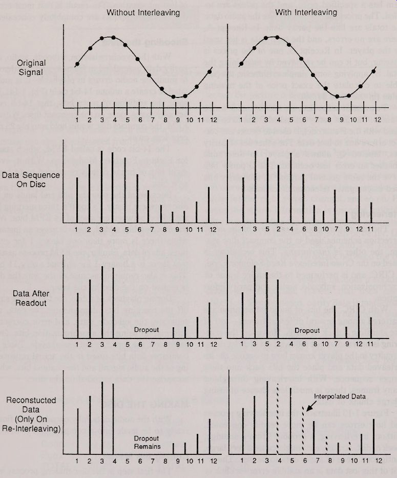
Fig. 1-13. The interleaving system shuffles and unshuffles data bits during
encoding and decoding to minimize the effects of dropouts.
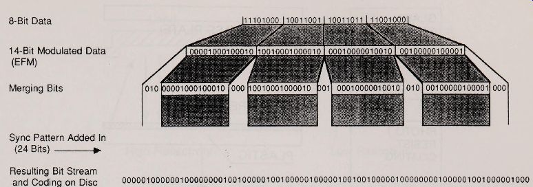
Fig. 1-14. The Eight -to-Fourteen encoding process, with merging and synchronization
bits added to the mix Table 1-2. Frame Format.
Cutting the Master
The first step in the disc-making process is to create the metal master. This process is shown in Fig. 1-15. This is done by taking a very smooth and highly polished glass plate and coating it with plastic on one side and photo resist on the other. The plastic acts to protect the glass disc, and the photo resist creates a light sensitive layer.
The coated disc is placed on the cutting rig (sometimes called the optical lathe). A turntable spins the disc while a precision laser exposes portions of the photo resist. The laser light is modulated by the encoded digital data. After exposure to the laser light, the disc is developed. Pits are formed where the laser was turned on.
Contrary to popular belief, the pits do not represent binary 1’s and the lands binary 0's. Rather, a binary 1 occurs at every pit / land and land/ pit transition. Everything else is a binary 0. Figure 1-16 graphically shows this.
This encoding process is infinitely more workable that using pits and lands to separately represent 1’s and 0's. It is also why the audio data is converted to EFM format and why merging bits are added. The EFM/ merging bit process ensures that there will never be a pit shorter than the time it takes to encode three binary digits, and no longer than 11 binary digits. You'll sometimes see the CD data encoding format expressed as 3T-11T, with the letter " T" meaning time intervals (one time in terval is equal to one bit ).
After the master has been developed, it is silvered, and then nickel plated. The metal master is now complete, and is carefully inspected to ensure that there are no surface blemishes.
Duplicating Discs
The metal master is used to make an intermediate master or mother." The mother is then used to make the stampers. It is the stampers that cre ate the distribution copies that are purchased in record stores. See Fig. 1-17.
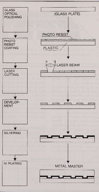
Fig. 1-15. Cutting a disc--from the glass plate to the metal master.
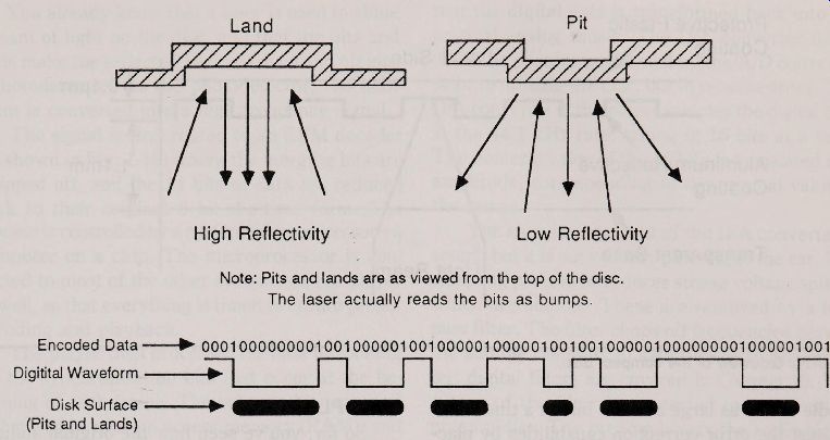
Fig. 1-16. The transitions between pits and lands represent binary 1;
everything else represents binary 0.
A stamped disc, called the signal layer, is nothing more than a thin 0.1 / im sheet of aluminum, coated with plastic on the top and bottom. The bottom coating is about 1.1mm thick and serves as the medium through which the laser in the player reads the aluminum stamping (Fig. 1-18). The top coating is much thinner--on the order of 10 to 20 um.
Imperfections such as bubbles in the bottom plastic coating can cause data dropouts. If the im perfection is large enough, the result ant data error can be heard as a click or pop. A very serious defect makes the player skip, just like an LP record.
But fortunately, such audible defects are rather rare.
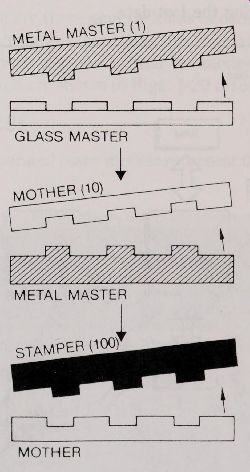
Fig. 1-17. Duplicating discs with intermediate stampers.
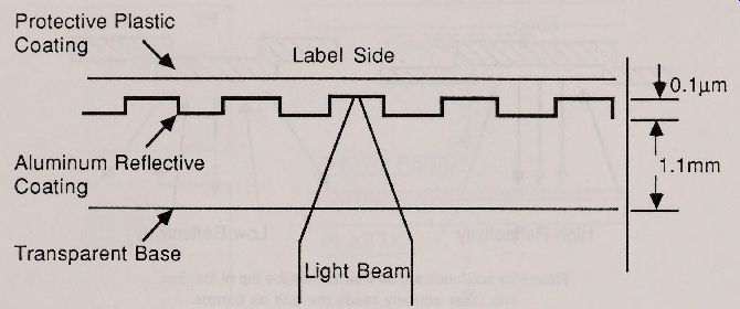
Fig. 1-18. Sideview of the compact disc.
At the surface of the disc, the beam from the laser in the player is about 1mm in diameter. By the time the beam reaches the aluminum stamping, it has been reduced to 0.8 / mi in size. A 1mm bubble near the surface of the disc is actually only a millionth in size on the signal surface-about the same as one or two pits. That’s not nearly enough to cause any serious trouble to the player.
Additionally, the parity and CIRC error correction schemes used in the compact disc System can handle errors as large as 3584 bits at a time. You can test the error correction capabilities by placing a piece of 1/ 32-inch-wide graphics ar tt ape on the bottom of the disc. The tape acts to totally block out data, but the effects can’t be heard on playback The error is either fully corrected or concealed by interpolating the lost data.
DISC PLAYBACK
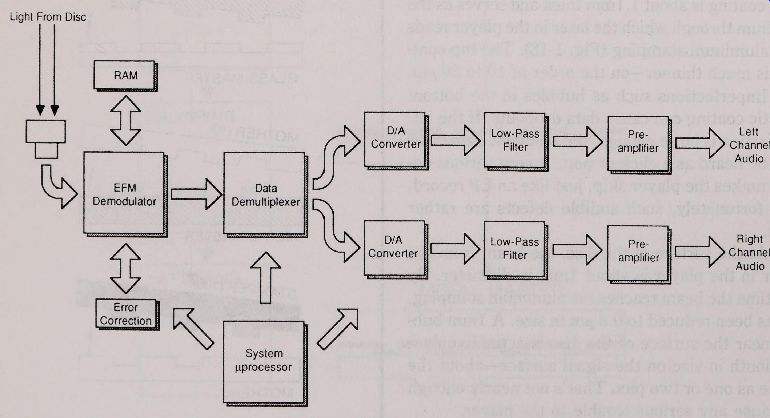
Fig. 1-19. Basic block of the main circuit blocks in a CD player.
So far, you've seen how the original audio is transfer red to digital form, mixed with other im portant pieces of data, and used to make a master disc and subsequent copies. To complete the picture, we resume our brief discussion on how the sound is recreated in the compact disc player.
Data Conversion
You already know that a laser is used to shine a beam of light on the disc, and that the pits and lands make the reflected beam flash on and off into a photoDetector. At the photoDetector, the light beam is converted into a high frequency signal.
The signal is first routed to an EFM decoder (as shown in Fig. 1-19) where the merging bits are stripped off, and the 14 bits of data are reduced back to their original 8-bit-at-a-time form. The process is controlled by a system microprocessor--a computer on a chip. The microprocessor is connected to most of the other Systems on the player as well, so that everything is timed to ensure proper decoding and playback.
The player then processes the data by looking forthe synchronization bits that occur at the beginning of each frame. The subcode bits are read and stored in random access memory (RAM), and the audio data is collected for processing. If a dropout or loss of signal is detected, the parity bits are used to recreate the lost information, if possible.
From here, the design of many compact disc players vary greatly, but here is one method of conver ting the digital data to analog sound (other methods are covered in greater detail in Section 2). The audio bits are first sent to a demultiplexer circuit that separates the one stream of digital data into the two stereo channels.
The audio bits are applied to a pair of digital to-analog (D/A) Converters (sometimes built into integrated circuit ). It is in the D/A that the digital data is transformed back into the original analog music. The D/A converter duplicates the process performed by the A/D converter pr ior to making the disc, but in reverse order. The D/A converter in the player samples the digital data at the 44.1 kHz rate, taking in 16 bits at a time.
The numeric value of the 16 bits is translated into amplitude, corresponding to the original value of the music.
The signal coming out of the D/A converter is sound, but it is not yet very pleasing to the ear. The sampling process introduces strong voltage spikes, which are audible. These are removed by a low pass filter. The filter chops off frequencies beyond the audible range of 20 kHz (this is an analog filter ; digital filters are covered in Section 2). The output of the filter is connected to a low-power preamplifier. The preamp boosts the audio signal to a level that can be better handled by the amplifier in your stereo system.
THREE KINDS OF PLAYERS
There are three general kinds of compact disc players on the market today: ac operated home models, portable models, and car models. Exam ples of each are shown in Figs. 1-20 through 1-22.
Home CD players
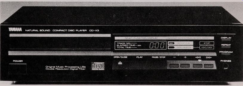
Fig. 1-20. A typical front loading ac operated home player.
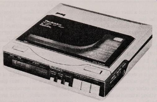
Fig. 1-21. Battery-powered portable players let you listen to discs while on the go.
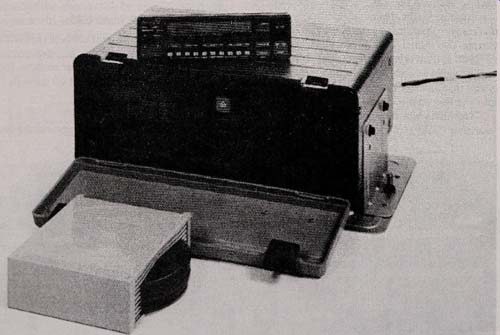
Fig. 1-22. This automotive CD player fits in the trunk and holds up to
10 discs.
You control it from inside your car.
Ac operated home models represent the largest group of CD players, and are the most diverse.
Home models can be Further divided into top loaders and front loaders. There are two forms of front loading mechanisms-drawer and door (more about these in Section 2). A few home models have automatic disc changers. You load from five to 60 (yes, sixty) discs and play some or all of them.
Portable CD players
Portable models are designed for on-the-go listening, and although most come with an ac adapter, they are specifically designed for battery operation. With some models, the batteries are an integral part of the player; with most others, the batteries are included in a special case. To use the player as a portable, you place it in the car rying case, where electrical contact to the batteries is made. You listen to the player through a set of stereo headphones.
Car CD players
Car CD players are gaining in popularity. Most models are now sold with an integral AM/ FM stereo) although you can buy a stand-alone CD player for use with your existing tape deck. A player for use in a car lacks an amplifier. You need to connect it to an amp to listen to the sound.
With most car CDs, you load the disc manually into a slot in the front of the player. As with the high-end home players, a few models forthe road have automatic disc changers. The whole contraption fits in your trunk, out of sight. You can select the specific disc and track you want to listen to by pushing buttons on a wired remote control.
= = = =