Joining the ranks of great expressions such as "The check is in the mail, and We service what we sell," is "All compact disc players are alike." The statement simply isn’t true. In fact, no two CD player models are designed or manufactured exactly the same. That means the music one player reproduces might sound considerably different than the sound from another.
While it is true that the digital nature of compact disc helps ensure a kind of mass standardization among CD players, the standardization does not inhibit technological advances in player design.
Compact disc players differ greatly in the way they retrieve information from the disc, process it, and reconst it ute it into analog sound. For a full appreciation of the compact disc medium, and to better understand the varied mechanics of player design and Maintenance, read this section on how CD players work.
Outwardly, CD players differ the most in their DISC LOADING method of disc loading.
Home Players
The ac-operated home players can be either front or top loading. Top loading CDs are the simplest of the bunch. You justopen the top door, like the hood of a car, slip the disc in, push the door closed, and start the disc. On a mechanical level, the simplicity of the design means there is no disc loading mechanism to foul up so less can go wrong.
On a purely ergonomic level, top loaders are not generally as desirable as front loaders because you can’t stack the player in with your other hi-fi gear.
Front loading players are either the drawer or door variety. The drawer loading type is shown in Fig. 2-1. Both use internal motors to open a sliding tray or recept acle forthe disc. You insert the disc on the tray or recept acle, which then closes, auto matically placing the disc into play position. Door loaders consist of a hinged door that pops down when you push the Open/ Close Switch, much like the loading door of a cassette deck. You slip the disc into the slot and shut the door Open/ Close Switch once again (on some models you manually push the door closed). Inside, a clamping mechanism presses the disc against the spindle. The disc spins ver tically.
Drawer loaders are a bit different. Pushing the Open/ Close Switch makes a tray-like drawer slide out of the player. You place the disc hor izont ally on the tray, then push the Open/ Close Switch again.
A clamper pushes the disc down into the drive spindle during play. The disc spins hoizontally.
While there is really no technical advant age to drawer loaders over door loaders, most current CD models are the former. A few door loading compact disc players still exist, but they are generally made with more mechanical parts and are harder to service.
A fourth type of home CD player is the changer. This is actually a subset of the drawer loading variety, but inst ead of inserting one disc at a time, you insert a special cartridge that holds five or more discs. You can play the discs individually by pushing the proper function buttons on the front panel of the player, or set the machine for continuous play.
Portable
Players All current portable players are considered top loaders, even though the playing mechanism may be located on the top front of the unit. With a por table CD, you push a button which releases a loading hat ch. You manually lif tthe loading hatch and place the disc in the player. Press the hatch back down and press Play. A typical portable CD is shown in Fig. 2-2.
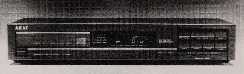
Fig. 2-1. Home player.
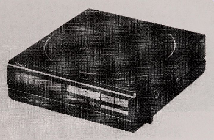
Fig. 2-2. Portable CDs are considered top loaders.
Car players are front loaders, but they don't employ the use of drawers or doors. With one type of car player you insert the disc into a wide slot in the front of the unit. Internally, the player grasps the disc and pulls it into play position. A clamper keeps the disc snugly against the drive spindle. Af -ter playing, the unit ejects the disc, you remove from the slot and return it to its jewel storage box. With the other type of car player, you first place the CD in a special cartridge and insert the cart r idge into the player. Manufacturers of players that use cartridges claim there is less chance of damage to the disc, but you must spend extra forthe cartridges. Some cartridge-load car CD players can accept up to 10 discs at a time. You select the disc you want to hear by pressing a wired remote control.
PICKUP TECHNIQUES
Compact disc players vary the greatest in ways that you can’t see. To begin, there are two general designs forthe optical assembly, which contains the laser diode, the photodetectors, and all the as sociated optics for relaying the beam from the laser to the photodetectors. The whole assembly is generally referred to simply as the optical pickup, or just pickup. The two types of pickups are the 1-beam and the 3-beam. A cut away view of the 3-beam type is shown in Fig. 2-3.
Contrary to what you may think, both types of pickups use only one laser. The difference lies in how the laser beam is split into smaller beams, and how the beams are manipulated within the pickup assembly. The 1-beam system was the first to come out, but most players use 3-beam pickups these days. There really is no technical advant age to the 3-beam System, at least not anything that can be proven.
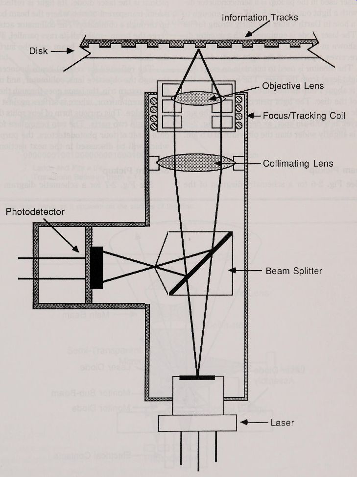
Fig. 2-3. A cut away view of the optical pickup system in a typical CD
player.
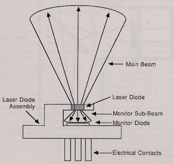
Fig. 2-4. The monit or diode is used to maintain an even light output
from the laser diode.
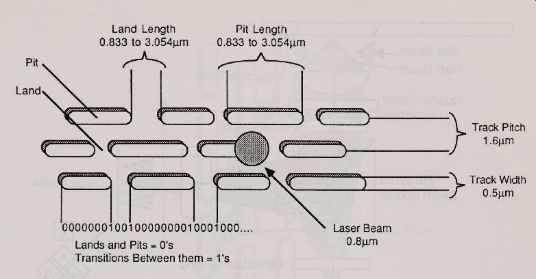
Fig. 2-5. The laser beam as it appears on the surface of the disc.
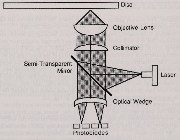
Fig. 2-6. The 1-beam optical pickup system.

Fig. 2-7. The 3-beam optical pickup system.
With both Systems, the pickup is mounted on a transport mechanism that moves it from the inside of the disc towards the outside during play The laser used in the pickup is a semiconduct or device with a light output of 3-5 mW--not enough to burn a hole in Darth Vader but fairly strong for its size. The laser diode is equipped with a monit or di ode, shown in Fig. 2-4. This is a detection device that receives a portion of the light emitted by the laser. The monitor is used to maintain an exact output light level from the laser. The beam from the laser is about 1 mm as measured on the plastic surface of the disc. The light penet rates through the plastic coating, and reduced in size, strikes the signal layer as a 0.8 ixm spot, as depicted in Fig. 2-5 This is slightly wider than the pit width of 0.5 um.
1-Beam Pickup
See Fig. 2-6 for a schematic diagram of the 3-beam pickup System. The 3-beam pickup has some of the same components as the 1-beam system, but is more complex. It necessarily requires a little more explanation, but it is well worth itit’s the most common System in use today.
The beam from the laser diode shines through a diffraction grating. The diffraction grating splits the light, making one main beam and two smaller sub-beams. Additional sub-beams are also generated, but these are weak and not used in the system.
The three beams then pass through a polarised beam splitter. This is a special optical component that consists of two pr isms with a common 45 degree face. The polarised beam splitter (or PBS) serves to pass the beam emit ted from the laser diode to the signal surface of the disc, then direct the reflected beam to the photo diode.
The PBS is designed so that it passes light polarised in one direction straight through, but reflects light that is polarised in the other direction. Forthe time being, the PBS passes the light from the laser diode straight through.
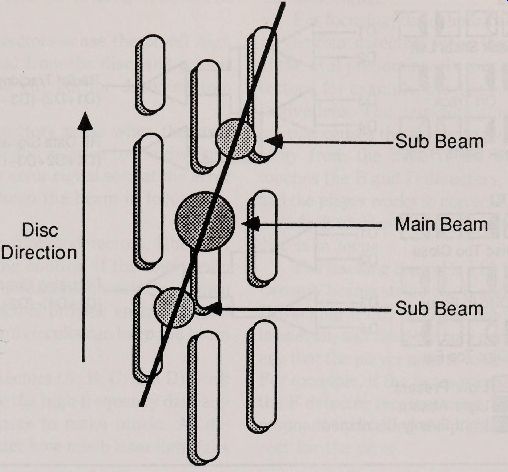
Fig. 2-8. The three beam system projects one large spot and two smaller
spots on the surface of the disc.
Prior to focusing the beams onto the disc, they are passed through a collimat or and quarter wave plate, or QWP. The QWP component shifts the polarization of the laser light by 90 degrees. After going through the QWP, the beams are focused onto the disc by the objective lens. Three distinct beams appear on the disc: one main beam that’s 0.8 um in diameter, and two slightly smaller and weaker ones ahead and behind the main beam, as shown in Fig. 2-8.
The three beams are reflected off the surface of the disc, where again they pass through the objective lens and through the QWP.
On the second time around, the QWP twists the light another 90 degrees. The light is now 180 degrees out of phase from the incoming beam, and is polarised in the other direction. If the beam from the laser diode is polarised hor izont ally, for example, passing the light through the QWP twice polarises the light vertically. The polarized beam splitter reflects the vertically polarised light to the photoDetector section of the pickup.
Once through the PBS, the beams are passed through a cylindrical lens. This kind of lens magnif ies or reduces an image in one plane only. It’s the same kind of lens used in movie cameras and projectors to make wide screen pictures. The main beam falls on a set of four photodetectors; the two sub-beams fall on Detectors of their own. The multiple role of these photodetectors is discussed in the next section.
FOCUSING AND TRACKING SYSTEMS
Directly linked to the pickup System is the way the compact disc player tracks the information pits on the disc, and at the same time keeps the laser beam in perfect focus. Again, the discussion will be divided between 1-beam and 3-beam Systems.
Tracking and focusing
Systems are critical to compact disc player design, because of the small olerances involved. The extremely narrow pitch of the information track is much like a tightrope of a circus performer. In a compact disc, the information track pitch is only 1.6 / im, several hundred times smaller than the wobble that’s present in all discs! Focusing is just as critical, with an equally small room for error. The laser pickup has a depth of focus of only ± 2 um. Yet discs commonly deviate as much as ± 0.6 um because of warpage.
1-Beam Tracking/ Focusing
See Fig. 2-9 for a schematic diagram of the 1-beam focusing/ tracking system.
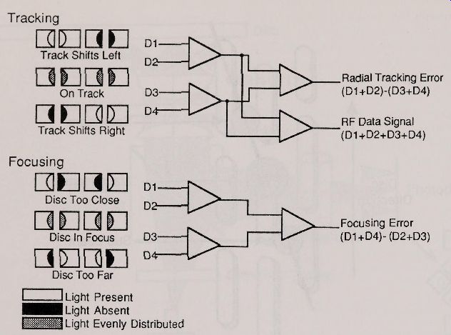
Fig. 2-9. The 1-beam focusing and tracking system.
As discussed above, the return laser light from the disc is split nt o two beams by the optical wedge. The two beams fall on a set of four photoDetectors, which serve a three-part purpose:
The photodetectors sense the on-of fhigh frequency EFM signal from the disc, and pass it along to the player’s circuits for decoding into music.
The photodetectors sense when the laser beam wanders off the track, and provides an error signal so that the tracking control circuits can keep the beam on target.
The photodetectors sense when the laser beam goes out of focus in relation to the disc surface, and provides an error signal so that the error control circuits can keep the beam in focus.
All four photodetectors work in tandem to generate the high frequency data signal that the player uses to make music. As designed, it doesn’t matter if all the laser light falls on one Detector or evenly on all of them. The player still receives the data signal.
For tracking control, the two light beams coming from the optical wedge are evenly distributed if the laser is precisely following the information tracks. If the laser beam wanders off to the right of the spiral of pits, too much light reaches the rightmost two diodes. The player detects this and advances the pickup to the left. The reverse occurs if the laser beam wanders off to the right of the in formation tracks.
Focusing is handled in a similar manner. When the disc is too close to the objective lens, the two light beams traveling through the wedge move closer toget her, thanks to an optical phenomenon first observed by J.B.L. Foucault in the 1850's. The two inner diodes get the bulk of the light int ensity, and the player corrects this by moving the objec tive lens down, and away from the disc. The reverse occurs when the disc is too far away from the objective.
3-Beam Pickup
See Fig. 2-10 for a schematic diagram of the 3-beam focusing/ tracking system. As you will recall, the 3-beam pickup employs six photodetectors. The main set of four photoetectors serve double duty, and are usually referred to as A, B, C, and D:
The photodetectors sense the on-of fhigh frequency EFM signal from the disc, and pass it along to the player’s circuits for decoding into music.
The photodetectors sense when the laser beam goes out of focus in relation to the disc surface, and provides an error signal so that the error control circuits can keep the beam in focus.
The remaining two photodetectors, labelede and F, are for tracking control. If the laser beam begins to veer off the information tracks, as shown in Fig. 2-11, the Detectors provide an error signal so that the error control circuits can keep the beam on target. All four photoDetectors (A, B, C, and D) work in tandem to generate the high frequency data signal that the player uses to make music. As designed, it doesn’t matter how much laser light falls on the individual Detectors, the player still receives the data signal.
For focusing, the cylindrical lens forms an oval on the four Detectors when there is a focus error.
If the oval predominantly touches the A and C deect ors, for example, the disc is too close to the objective lens. The Detectors generate an error signal that causes the player to move the lens Further away from the disc. If the oval predominantly ouches the B and D Detectors, the disc is too far, and the player works to correct it. If the light makes a circle, it touches all four detectors evenly, and the disc is in focus.
The tracking control is a bit more involved. The two sub-beams strike thee and F photodetectors.
If tracking if off, the light reaching the detectors is uneven, and the detectors generate an error voltage that the player uses to keep the beam on track.
For example, if the beam wanders off to the right, the F detector receives more light, and the player responds by inching the pickup to the right to correct forthe error.
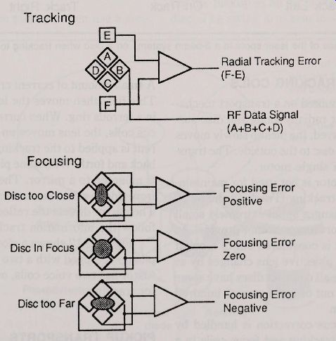
Fig. 2-10. The 3-beam focusing and tracking system.
-------------
Tracking Radial Tracking Error B (F-E) RF Data Signal (A+B+C+D) Focusing Focusing Error Disc too Close Positive Focusing Error Disc In Focus Zero Focusing Error Disc too Far Negative
------
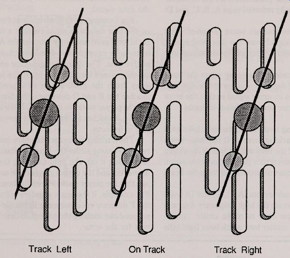
Fig. 2-11. The appearance of the laser spots in a 3-beam System, on a
disc when tracking to the left, to the right, and evenly down the track.
Track Left On Track Track Right
FOCUSING AND TRACKING COILS
The pickup is mounted on a transport mecha from the inside of the disc to the outside. The transnism, which moves it radially along the disc surface. As the disc is played, the pickup slowly moves por tis powered by a single motor.
The transport motor is not used for maintaining proper focus and tracking. Tracking and focus correction require changes on an extremely small scale that the transport motor cannot provide. As an example, the disc is considered out of focus if its distance from the objective lens changes by as little as + 2 (im. Since all compact discs have some warpage, they all go out of focus several hundred times each revolution.
Tracking and focus correction is handled by precision coils. The tracking and focus coils in a CD player are much like the voice coils in a speaker. A small amount of current creates a magnetic field.
This field then moves the lens, which is mounted in a ferrous ring. When current is applied to the fo cus coils, the lens moves up and down. When current is applied to the tracking coils, the lens moves back and forth. With some players, the tracking coil is mounted to a mirror. The mirror shifts slightly from side to side when current is applied to the coil.
The mirror directs the reflected beam to precisely follow the information track on the disc.
Figure 2-12 shows a closeup view of a 3-beam pickup equipped with a two axis act uator. This ac tuat or has two voice coils, one for focus, the other for tracking.
Fig. 2-12. The two-axis act uat or moves the objective lens up and down and right to left.
PICKUP TRANSPORTS
There are two kinds of transport mechanisms used to move the pickup across the disc: swing arm and slide.
Swing Arm
---------------------
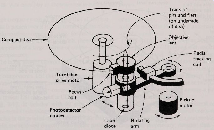
Fig. 2-13. A simplified view of the swing arm pickup transport.
Track of pits and flats (on underside of disc)
Objective Compact disc lens
Radial tracking coil
Turntable drive motor Focus Pickup motor
PhotoDetector diodes Rotating Laser diode arm
-------------------
Players with 1-beam pickups often use a simpie swing arm transport mechanism, shown in Fig. 2-13. The laser is mounted on one end of a low inertia balanced arm. On the other end, at the pivot point, is a motor. This motor swings the arm, moving the pick-up in an arc across the surface of the disc. The swing arm also incorporates a tracking coil for keeping the pickup centered on the information tracks. The tracking coil makes small corrections in the lateral position of the pickup.
With swing arm transports, the only true moving part is the pivot. This makes the swing arm system relatively immune to wear. Swing arm mechanisms are also small and light weight, so they are ideal for use in portable and automotive CD player use.
Slide
The design of the 3-beam pickup can't be used with swing arm transports, because the beam must always be kept at right angles to the tracks on the disc (remember, with the arm swing transport, the pickup is swept across the disc in an arc, so the angle of the tracks varies as the pickup moves along the radius of the disc).
The 3-beam Systems (Fig. 2-14) use a slide transport where the pickup is moved across the disc on a double-rail plat form. The slide (sometimes called the sled) is perhaps the most common transpor tused today, and is a favor ite among Japanese
CD player manufacturers. American and European manufacturers tend to favor the swing arm transport, but as more machines are designed with 3-beam pickups, the use of the swing arm transport will greatly be reduced.
Most slide transports consist of a motor-driven lead screw and matching gear that slowly moves the pickup along a set of alignment rails. A few slide transports, particularly those used in portable CD players, are designed as miniature linear motors.
There is no lead screw and gear; rather, the transport mechanism is in itself a motor. Coils at tached to the transport frame act as motor windings. The coils are mounted around a set of special laminated rails, which serve as the motor armatures. A second set of rails act as guides to keep the transport in proper alignment.
---------------------
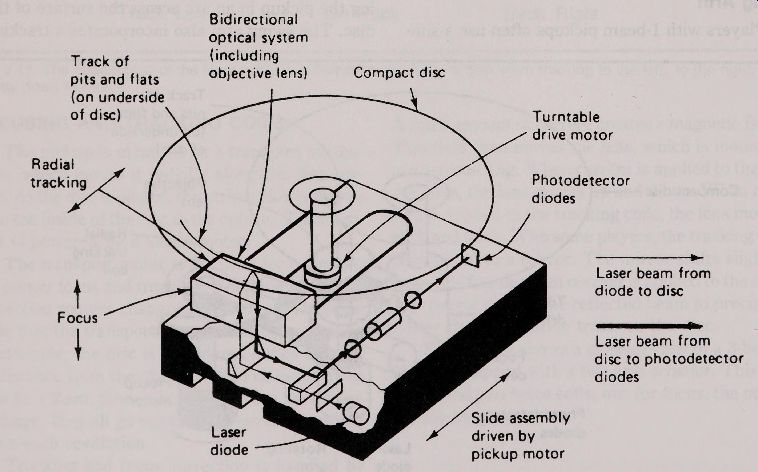
Fig. 2-14. A simplified view of the slide (or sled) pickup transport Bidirectional optical System (including Track of objective lens) Compact disc pits and flats (on underside of disc) Turntable drive motor Radial PholoDetector tracking diodes Laser beam from diode to disc Focus Laser beam from disc to photoDetector diodes Slide assembly Laser driven by diode pickup motor-----------
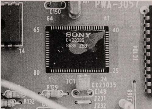
Fig. 2-15. VLSI
--------PROCESSING CIRCUITRY
The circuitry inside the player that processes the high frequency signal, insuring that all the music data is present -or if it isn’t, correcting the miss-ing information-comes in many forms. In some players, particularly the early models, these circuits are comprised of a large volume of off -the-shelf ICs and components.
The latest players incorporate LSI (Large Scale Integration) circuitry to greatly reduce the elect ronic components. LSI chips are cust om designed integrated circuits that combine the functions of a number of ICs and other components.
A typical LSI chip used in CD players is shown in Fig. 2-15. It bristles with 80 pins and uses surface-mount technology. The pins aren’t inserted into holes in the printed circuit board (PCB); Rather the pins are soldered directly onto solder pads on the underside of the board. Surface-mount components, which also include such common items as diodes, resistors, capacitors, and transistors, are soldered onto the PCB using automated robot assembly equipment.
LSI chips are often used as building blocks in the design of the CD player, with each block being a complete circuit. The main building blocks in a CD player are the preamplifier, EFM demodulator, racking and focus servo, System microprocessor, and D/A converter. In some players, these functions may be the domain of just one or two ICs; in others, the functions may spread among a half dozen or more integrated circuits.
The low parts count in the latest compact disc players reduces the chances of component failure, but it also makes servicing a real problem. The LSI hips are proprietary designs that are closely guarded by CD player manufacturers. You can't go o the neighborhood electronics store, for example, and pick up an extra EFM decoder. And since LSI chips can’t be easily soldered and de-soldered using manual soldering techniques, they are nearly impossible to replace if bad. Manufacturers recommended replacing the entire PCB if one of the LSI chips is defective. It may sound extreme, but it’s often cheaper and easier to exchange the whole board than tediously replace the LSI chip.
A Closer Look at CD Player Circuits
The following is a brief rundown of the general purpose of the main building block circuits of the compact disc player, and how they work with one another. Refer to Fig. 2-16 for a block diagram of these circuits as used in a typical player.
Preamplifier
The preamplifier receives the signals from the photo Detectors and amplifies them for use by the rest of the player. Amplified signals are sent to the System microprocessor, EFM decoder, and servo circuits.
EFM Demodulator
The EFM demodulator (also called the EFM decoder ) decodes the high frequency EFM signal generated by the photodiodes and boosted by the preamplifier. The decoding process is performed in the reverse order as data encoding, described in detail in Section 1.
Briefly, the EFM demodulator detects the synchronization bits that mark the beginning of each audio frame and strip the merging bits from the 14 bit code. The EFM signal is then reconverted to its original 8 bit digitized format.
In many players, the EFM demodulator also serves as the dropout error detector. If EFM data is lost due to a data dropout, the parity and CIRC correction circuits in the EFM decoder recreate or conceal the error.
The output of the EFM demodulator feeds into the D/A converter.
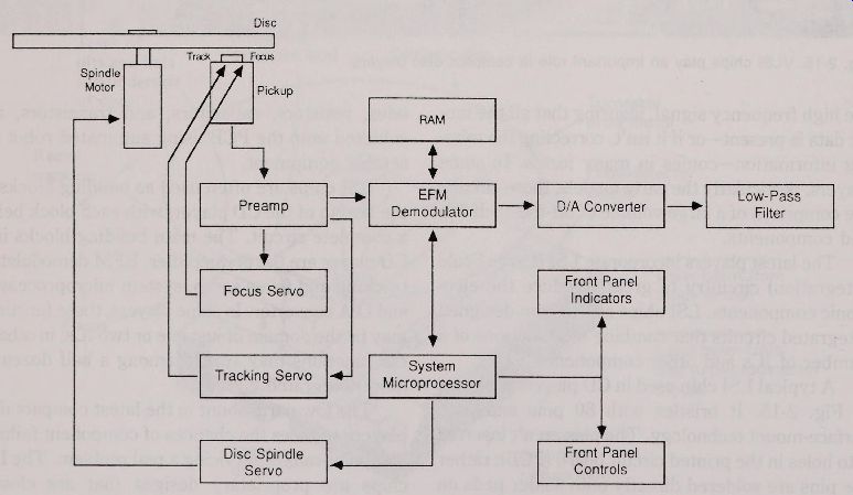
Fig. 2-16. The main blocks of the CD player. The System microprocessor
maintains smooth operation.
Tracking and Focus Servo
In both 1-beam and 3-beam systems, the photo setectors serve to capture the EFM signal forthe EFM demodulator, and also to provide tracking and focus error signals forthe tracking and focus servo.
The signals from the photo detectors is first boosted by the preamplifier, then passed to the tracking and focus servo (which can be one circuit or separate circuits). The servo generates control voltages for operating the tracking and focus coils.
System Microprocessor
The System microprocessor assures that all the components in the compact disc player operate in tandem. The processor also serves as the communications link between the front panel controls and indicators, as well as player electronics.
On models with a programmable memory function, the system microprocessor accepts programming entry and stores it for execution. Advanced players employ electrical erasable programmable read only memory (EEPROM) for permanently storing ''favorite selections" for retrieval at any time. The EEPROM retains its memory, even when the player is unplugged, until reprogrammed.
Support Electronics
All CD players are operated by a system clock running at 4.3218 MHz. The clock is governed by a quartz crystal oscillator for precise timing. Some players incorporate additional "sub-clocks" for controlling different components. However, the recent trend is to design players with one master clock.
The pulses from the clock are divided into other frequencies for use by the various components. The master clock prevents multiple clock pulses from interfering with proper D/A conversion.
CD players employ random access memory (RAM) for temporarily storing EFM data (the RAM can be built into the EFM demodulator ). The function of the RAM is to act as a data reservoir during playback. It assures that the D/A converter receives a steady stream of data, even if the rate of data retrieved from the disc fluctuates. (Section 3 supplies more information on the function and operation of the RAM.) A disc spindle servo and associated voltage controlled oscillator circuits keep the disc spinning at the proper speed. The disc spindle servo is under the control of the System microprocessor. If the disc begins to spin too fast, the microprocessor tells the servo to decrease the speed. Conversely, if the disc spins too slow, the microprocessor tells the servo to increase the speed.
The front panel controls and indicators let you command the player. Pushing a button on the panel command the microprocessor, which in turn decides how to act on your instruction. Some players have a separate microprocessor that handles just the front panel controls. This microprocessor works under the supervision of the System microprocessor. Playback information is shown on the front panel indicators.
D/A
The D/A converter is one of the most import ant electronic components of the compact disc system. As with the laser pick-up mechanism, players use a variety of D/A converter designs.
The overall function of the D/A converter is to take the 16 bits of digital data output by the EFM demodulator, sample the data, and provide an analog signal based on the value of the binary digits decoded from the disc.
It sounds simple enough but there is a flaw in the basic design of all D/A Converters, one that has the potential to ruin the sound of the CD player.
The sampling circuit in the D/A converter creates a voltage spike at each sampling interval, as depicted in Fig. 2-17A. This isn't desirable by any means, and it isn't music, so the D/A converter in eludes another internal component called the hold circuit. The hold circuit maintains the voltage level of the sample until the next sampling period. As shown in Fig. 2-17B, the result is a stairstep-shaped wave, which follows the cont ours of the analog output.
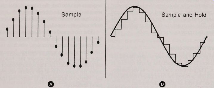
Fig. 2-17. A. Sampling Introduces voltage spikes. B. A hold circuit maintains
the voltage level of each sample until the next one arrives, to help
reduce the spikes.
Significant frequency components, or harmonies, of the original sampling spikes still remain, despite the smoothing action of the hold circuit.
These harmonics are particularly strong in the 25 to 44 kHz range, but continue on up the frequency spectrum to infinity. The harmonics are centered around multiples of the sampling frequency. That is, there is a series of harmonics centered around 44.1 kHz, 88.2 kHz, 132.3 kHz, and so forth.
Most of the frequencies are inaudible (called " out -of -band" ). But some harmonics can extend into the normal hearing range, or at least affect those frequencies that we can pick up with our ears.
A r ilter, either built into the D/A converter or added just pr ior to the audio preamp in the player blocks unwanted frequencies above 20 kHz.
There are two general types of D/A Converters in common use in CD players-normal sampling and oversampling-and they use different kinds of filtering techniques. Let’s take a look at each one below.
Normal Sampling
The typical D/A converter, using normal sampling, examines the data originally encoded on the disc at the CD standard of 44.1 kHz (see Fig. 2-18).
The sample and hold circuit(s) in the D/A converter samples each 16 bit word from the EFM decoder and holds it until the next sampling period. As explained above, the sampling spikes are partially suppressed by the hold circuits in the D/A converter as the waveform is converted to its blocky stairstep shape.
The spikes are further reduced by the addition of a low-pass filter at the analog output of the D/A converter. The low-pass filter is a necessary component of the normal sampling D/A converter.
When used with just a low-pass filter, the player is said to have analog filtering.
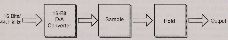
Fig. 2-18. Simplified block diagram of the D/A converter and sample/hold
circuits in a player that uses analog filtering.
Figure 2.19 shows a simplified block diagram of the signal path from the EFM demodulator to
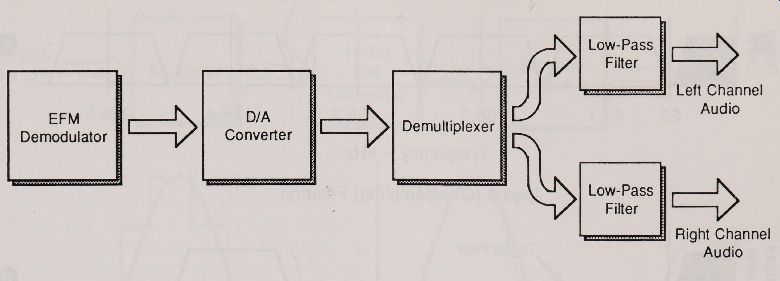
Fig. 2-19. Simplified block diagram of analog filtering.
0 the stereo low-pass filters. In this diagram, the converted analog signal is passed through a demultiplexer, a fast acting electronic Switch that alternat es the right and left stereo information into the two channels.
The design of the low-pass filter is an import ant one, and it determines the overall frequency response of the player. The filter is designed to leave frequencies below 20 kHz untouched, but suppress everything above it. To obtain such a sharp drop-off, the filter is designed as a type of electronic brick wall.
Try as they might, however, engineers cannot make an analog filter that chops off all frequencies above 20 kHz, without affecting at least some of the frequencies below. The response curve of most analog filters employed in CD players starts to drop 0.5 dB or so after 16 or 17 kHz, then fall dramatically to 1 dB or more as it approaches 20 kHz.
To be effective, the filter must totally suppress all frequencies at or above 25 kHz, where the sampling frequency components are their strongest. Figure 2-20A illustrates the action of the analog filter. The black portion is the range (or ''pass'') of the filter. Note the slope of the filter as it approaches 25 kHz. The harmonics of the sampling spikes still remain, centered at 44.1, 88.2, 132.3, 176.4, 220.5 kHz, and so on.
Oversampling
One solution to the problem of sampling spikes and steep filter cut off is oversampling.
With this technique, sampling spikes are effectively removed in the frequency range spanning from 25 kHz up to the oversampling frequency, which is usually 88.2 kHz or 176.4 kHz (see Fig. 2-20B). Oversampling is often referred to as digital filtering, because the sampling spikes are suppressed digitally, be fore they are converted to analog form.
Here's how oversampling works: Instead of sampling the incoming data 16 bits at a time every 44.1 kHz, the digital data is multiplied two times or four times--to 88.2 kHz or 176.4 kHz, as shown in Fig. 2-21. Most D/A Converters in present day compact disc players oversample four times.
With 4X oversampling, for example, the noise power originally confined to a band from 0 Hz to 22 kHz is now spread out over a band four times as wide, or 0 Hz or 88 kHz. So the sampling spikes are only one quarter their original strength. A digital noise filter built into the D/A converter acts to limit the sampling spikes even more.
Sampling noise still occurs, but the bulk of it is confined to a region around the oversampling rate, well out-of-band. Here, conventional low-pass analog filtration, when used at all, can easily remove the harmonics from the sampling spikes.
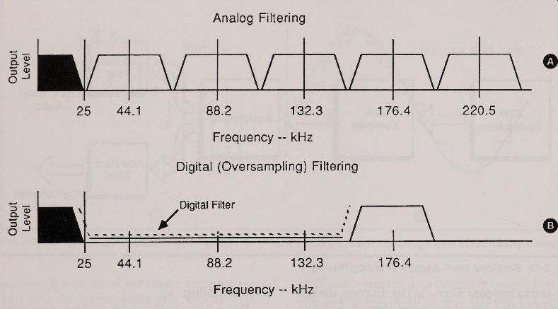
Fig. 2-20. A. Analog filtering does not reduce the voltage transients
above 20 kHz but at tempts to block them. B. Digital filtering reduces
and blocks voltage transients beyond 20 kHz.
Figure 2-22 shows a simplified block diagram of the signal path from the EFM demodulator to the stereo channel low-pass filters. In this diagram, the digital filter is the portion of the circuit that oversamples the incoming data. It is then separated into in its right and left stereo components, and passed through separate D/A Converters*
14 Bit Vs. 16 Bit
The first oversampling systems, developed by Philips, used a 14 bit D/A converter that simplified the digital filtering components, but still maintaining a reasonably high dynamic range of 84 dB or greater (the theoretical dynamic range of compact disc players, which is determined by the number of bits in the quantized sample, is 96 dB or greater ).
In this System, the 16 bit/44.1 kHz data from the EFM demodulator is passed through a digital oversampling filter. It comes out as 28 bits sampled at 176.4 kHz. A noise shaper and passive digital filter reduce the output to 14 bits at 176.4 kHz. This output is applied to the sample and hold circuits of the D/A converter. The 14-bit system has fallen into disuse, however, by the development of true 16 bit oversampling D/A converters, which are now used in most present -day CD players.
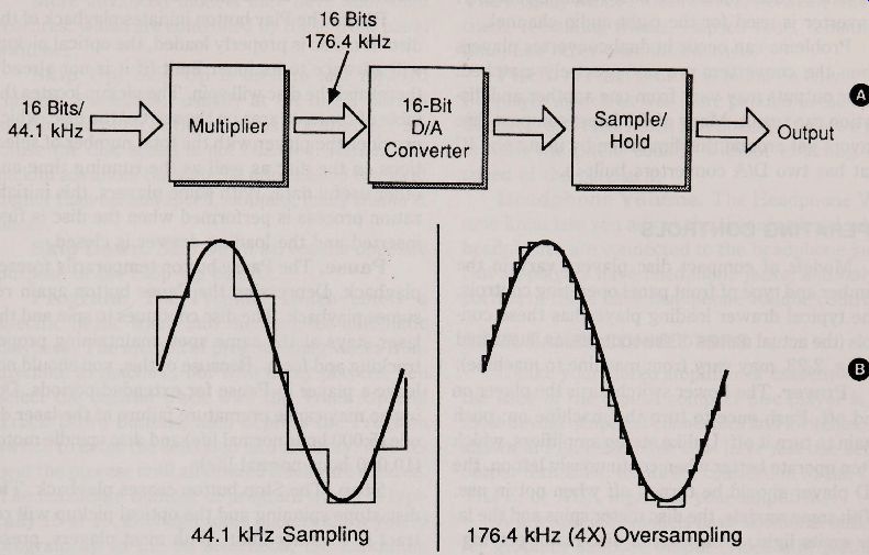
Fig. 2-21. A. Simplified block diagram of the D/A converter and sample/
hold circuits in a player that uses digital filtering. B. Normal (44.1
kHz) sampling and 4X (176.4 kHz) oversampling. 44,1 kHz Sampling 176.4
kHz (4X) Oversampling
ONE OR TWO CONVERTERS
CD players can have either one or two D/A converters (some have even more). With one-converter players, the audio information from the EFM decoder is received as combined right and left channel information. The D/A converter processes the single stream as usual, and passes the resulting analog signal to an electronic switch. The switch sequentially toggles between right and left channels.
One-converter players are capable of superb sound, and they are less expensive to manufacture, but they are susceptible to switching distortion.
They are also prone to interchannel phase distortion, which is when the sound from the right and left channels do not exactly match up in time. (See Section 3 for more information about interchannel phase response.)
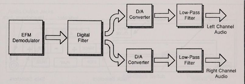
Fig. 2-22. Simplified block diagram of digital filtering.
Players with two D/A converters lick this problem. Before digital-to-analog conversion, the data stream from the EFM demodulator is broken down into its right and left channel components. One D/A converter is used forthe left audio channel; one D/A converter is used forthe right audio channel.
Problems can occur in dual-converter players when the converters are not precisely matched.
Their outputs may vary from one another and distortion can result. Many of the latest compact disc players get around this limitation by using one IC that has two D/A Converters built -in.
OPERATING CONTROLS
Models of compact disc players vary in the number and type of front panel operating controls.
The typical drawer loading player has these controls (the actual names of the controls, as illustrated in Fig. 2-23, may vary from machine to machine):
Power. The Power Switch turns the player on and off. Push once to turn the machine on; push again to turn it off. Unlike stereo amplifiers, which often operate better when continuously left on, the CD player should be turned off when not in use.
With some models, the disc motor spins and the laser emits light, even when a disc is not playing.
Open/ Close. The Open/ Close Switch acts as a toggle to open the disc loading drawer or to close it. Push once to open; push again to close. Many players have sensing Switches inside the loading tray. These Switches Detect pressure on the tray so the drawer will ret ract if manually closed. This prevents possible damage to the loading drawer. Pushing the Play button (described below) on most machines also closes the drawer.
Play. The Play button init iat es playback of the disc. If a disc is properly loaded, the optical pickup will advance to its inner limit (if it is not already there) and the disc will spin. The pickup locates the table of contents area on the start of the disc, which provides the player with the total number of selec tions on the disc as well as the running time and other useful data. With some players, this init iali zation process is performed when the disc is first inserted and the loading drawer is closed.
Pause. The Pause button temporarily freezes playback. Depressing the Pause button again resumes playback. The disc continues to spin and the laser stays at the same spot, maintaining proper tracking and focus. Because of this, you should not leave a player in Pause for extended periods. Doing so may cause premature failure of the laser di ode (5,000 hour normal life) and disc spindle motor (10,000 hour normal life).
Stop. The Stop button ceases playback. The disc stops spinning and the optical pickup will retract to its inner limit. With most players, pressing the Stop button also turns the laser diode off.
Track Up. The Track Up button advances the pickup through each selection, or music track, one at a time. Repeat edly depressing the Track Up button, or keeping it depressed, advances sequentially through all the tracks.
-----------------
Fig. 2-23. The front panel controls and indicators on
a typical home CD player.
Indicator, Headphone Jack, Loading Drawer , Switch Loading
OPEN/ CLOSE, TRACK SKIP, STOP, PAUSE, PLAY, POWER
Power Switch, Track Selectors, Skip Selectors
--------------------
Track Down. The Track Down button serves the opposite purpose of the Track Up control.
More advanced models may have additional features, which are controlled by these front panel Switches:
Skip Up. Skip Up is used to fast forward through a selection, usually at 4X to 8X normal speed. The pitch of the music is not affected, because the disc speed is not changed. Rather, the pickup advances through the information tracks at higher than normal speed, skipping many tracks at once.
Skip Down. Skip Down serves the opposite purpose of the Skip Up control.
Program. The Program Switch enters a specific music track into memory for automatic playback. The method of programming varies from machine to machine, but with many players, you select the desired track with the Track Up and Track Down buttons, then depress the Program Switch to enter the selection into memory. You repeat the process until all desired tracks are entered.
The maximum number of program tracks is typically 15 or 16, although some players allow you to program up to the 99 selections, the maximum number of music tracks that a compact disc can contain.
Repeat. The Repeat control allows you to play a disc through twice.
Display Mode. The indicator panel on most compact disc players is too small to display at once all of the user information provided by the player. The Display Mode Switch selects between current track, remaining tracks, elapsed time, remaining time, and other user information.
Pitch. A Pitch control is found on only a few CD player models (it was more popular in the early CD days, but it has fallen into disuse). It allows you to alter the pitch, usually without effecting the speed of the playback.
Headphone Volume. The Headphone Volume knob lets you adjust the listening level when
headphones are connected to the headphone jack.
Not all players have headphone jacks, and only a portion of these have headphone volume controls.
Fig. 2-24. The back panel connectors and Switches on a typical home CD
player.
+ Audio Output Jacks Anti-Shock Switch Power Cord
REAR PANEL CONNECTORS
Unlike your stereo amplifier or cassette deck, the back of the typical compact disc player is al most devoid of special connectors and Switches. As shown in Fig. 2-24, most CDs have just one set of outputterminals, for direct connection to the CD, TAPE, or AUX inputs of your amplifier.
A few specialty models have additional out lets, for graphics subcode output (video still pictures from subcode data), and direct digital data output.
Some models also have an ''anti-shock" switch, which can help prevent excessive mistracking when the player is subjected to light vibration. You should normally keep the ant i-shock Switch off, as it can cause greater-than-normal skipping when playing a moderately scratched disc.
REMOTE CONTROL
An increasing number of CD players come with wired or wireless remote controls. The control transmit ters duplicate some or all of the player front panel operations. Players vary widely in the num ber of functions found on the remote control transmit ters. The majority of remote controllers have about seven functions: Play, Stop, Pause, Track Up, Track Down, Skip Up, and Skip Down. Other controllers duplicate every function on the front panel of the player (even those used for track programming). A recent trend is to use one remote control for both CD and amplifier / receiver.
= = = =