AMAZON multi-meters discounts AMAZON oscilloscope discounts
Lesson AEH-14A
ELECTRONS CONTROL MOTORS
Often it is desirable in industry to operate heavy equipment in tandem. For instance the paper may need to pass through two presses or the sheet metal must go through two rolling mills. To accomplish this feat, the machines must have identical feed speeds or the material will break, stretch, or tangle while passing from one to the other. To obtain these identical speeds, electronic motor controls are employed.
In fact, to start large motors manually, requires skill. To avoid risk of serious dam age to the motor and expensive delays in production, it is now customary to employ electronic controls to start, stop, reverse, or maintain the speed or torque of the motors automatically as predetermined by the operator.
Fundamentals
THREE ELECTRODE TUBES
Contents
Triode Construction
Function of the Grid
Triode Characteristics
Triode Amplification
Things don't turn up in this world until somebody turns them up.
- Garfield
THREE ELECTRODE TUBES
In addition to the basic circuit properties of resistance, inductance, and capacitance; several explanations of the earlier les sons have mentioned the importance of electron tubes. In fact, the present development of radio, television, and communications; and the rapidly increasing applications of electronics are due mainly to the many duties these tubes can perform.
With no mechanically moving parts, they act as switches of almost unlimited speed, as rectifiers to allow current in one direction only, as generators of alternating current from low to ultra high frequencies, as amplifiers to increase the magnitude of a-c voltages or current, and as detectors to indicate and measure minute quantities of electric energy.
By itself, the electron tube has only a few applications but when combined with the other components, such as resistors, capacitors, and inductors, its internal actions permit many more applications than the few just mentioned. Furthermore, with the proper external connections, electron tubes can be made to act as resistors, inductors, or capacitors that vary as desired with the changing electric conditions in their circuits. This action alone forms the basis for countless automatic electron controls.
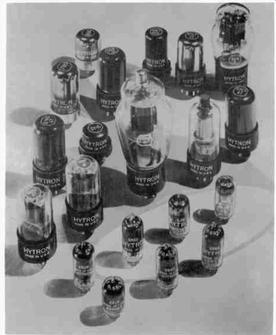
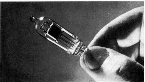
------------- These are but a few of the large number of tubes having various
sizes and shapes that are used in electron equipment. In fact, all of the tubes
shown here are used in one television receiver. Courtesy Hytron Radio and Electronics
Corp.
To serve these many purposes, electron tubes are made in a wide variety of sizes and types. However, all tubes consist of two or more conductive elements or electrodes enclosed in an evacuated glass or metal envelope.
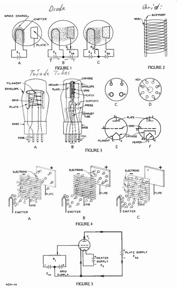
The simplest form of tube, the diode, was explained in an earlier lesson as a rectifier. As its action is basic, a drawing from this earlier lesson is reproduced here as Figure 1.
The plate current of the diode tube is controlled by the number of electrons emitted from the emitter and the magnitude of the plate voltage. Starting with the conditions of Figure 1A, the emitter is heated to its normal operating temperature by voltage source E1. Without an external connection, the plate voltage is zero, and with no attraction by the plate, the emitted electrons form the space charge around the emitter. Under these conditions, the plate current is zero.
In Figure 1B, the plate is connected to the sliding contact of the variable resistor R1 , one end of which is connected to the positive terminal of the plate supply battery E,,,,. The Eh), negative terminal connects to the emitter.
Each position of the R1 sliding contact varies the resistance in series between the plate and the positive terminal of E.,. Carried by resistor lt,, the plate current causes voltage across it. There fore, the plate voltage can be varied by moving the sliding con tact of R1 . With the sliding contact at the open end of resistor R1 , maximum resistance is in the circuit, and the plate is just slightly positive with respect to the emitter and only a few electrons are drawn from the space charge.
As the slider is moved closer to the connected end of resistor R1 , less resistance is in the circuit and the voltage across the resistor is reduced. With less voltage across R1 , the plate becomes more positive, a corresponding larger number of electrons are drawn from the space charge, and so the plate circuit current increases.
For any given emitter temperature, the positive plate voltage can be increased, until the plate attracts all of the emitted electrons. Raising the plate voltage above this value does not increase the plate current. This maximum is called the SATURATION CURRENT, and the plate voltage necessary to produce it is called the SATURATION VOLTAGE.
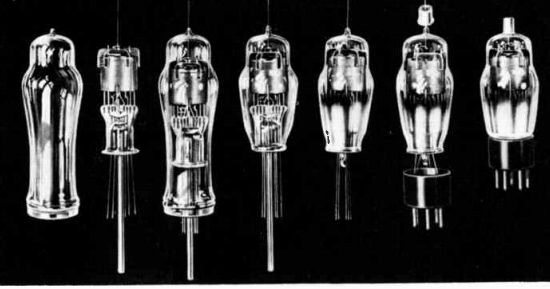
--------------- Several steps are necessary in the assembly of an electron
tube. Many tubes have the grid connection at the top. One reason for this is
the large separation between plate and grid connections. Courtesy Sylvania
Electric Products Co.
In the circuit of Figure 1C, battery E,,,, maintains the plate at a constant potential with respect to the emitter, but a variable resistor R, is placed in series with the emitter. As explained for R, of Figure 1B, changing the position of the sliding contact varies the total resistance of R.,. With a constant voltage source E1 , these changes of circuit resistance change the emitter current. Since the heat varies directly with the current, the variable resistor controls the emitter temperature.
As the temperature is increased, more electrons are emitted and the density of the space charge increases so that more electrons are available for attraction to the plate. As a result, the plate current increases although the plate voltage remains constant. however, by continuing this action, a point is reached eventually, at which the repelling action of the space charge is so great that a further increase in temperature causes no increase in emitted electrons. Hence, for a given plate voltage, the emitter temperature above which the plate current does not increase is called the SATURATION TEMPERATURE. Thus, by varying either the emitter temperature or the plate voltage it is possible to control the plate current. However, neither method provides any real ad vantages. The same control can be accomplished by a simple potentiometer without the use of the tube.
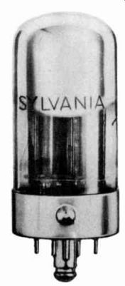
-------------- This loctal type tube is held securely in its socket by
a locking arrangement of the center guide pin at the bottom of the tube. Courtesy
Sylvania Electric Products Co.
TRIODE CONSTRUCTION
In 1907, Dr. Lee deForest placed a third electrode between the emitter or cathode and plate of the diode type tube. The additional electrode, now known as a grid, constituted one of the important steps in the development of the field of electronics, for by placing voltages on the grid, it controls the flow of the electrons in the plate circuit. In fact, the flexibility of this arrangement is so great that its applications are proving limitless.
As pictured in Figure 2, usually the grid consists of a coil of wire held in position by two vertical supports. In most types, the wire is made of molybdenum, since this metal is a very poor emitter of electrons, and the space between turns is so large, compared to the diameter of the wire, that there is practically no physical obstruction to electrons passing through the grid coil.
A three-electrode tube of this general type is called a triode, using the prefix "tri" which means three. The emitter or cathode may be directly or indirectly heated and the plate usually is a cylinder, which is very similar in material and construction to that used for a diode.
In Figure 3A, the plate is cut away to show the arrangement of the elements in a directly heated emitter or filament type of triode which at one time was popular.
Since the grid surrounds the filament and the plate surrounds the grid, all electrons flowing from the filament to the plate pass between the turns of the grid coil.
Figure 3B illustrates a more modern triode tube with an indirectly heated emitter known as a cathode. To start the assembly, a number of support wires are em bedded in a piece of glass called the press. All of these wires extend upward to serve as supports and some of them extend down ward to provide connections for external circuits. The press is hollow to provide an exhaust tube with openings at both top and bottom.
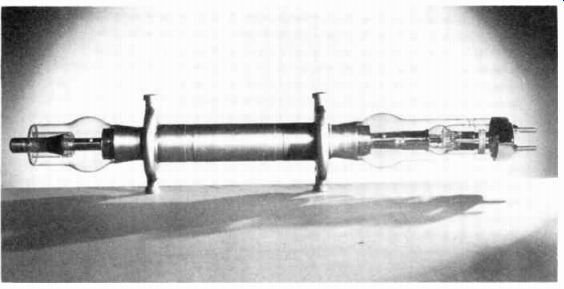
----------- This triode is used in large broadcasting stations. Since it
conducts heavy current, it is water cooled. Courtesy Western Electric Co.
The heater is mounted on the two central support wires, both of which extend through the opposite end of the press. In the same way, the cathode and grid are mounted separately on supports which also extend through the opposite end of the press. The plate is mounted on the two outer supports only one of which extends through the press.
This assembly of mounted electrodes is placed inside the envelope, the lower end of which is fused with the lower end of the press. Thus, the electrodes are en closed in an airtight space, and, by a vacuum pump attached to the lower or outer end of the exhaust tube, the air is removed from inside the envelope. When this process is complete, the outer end of the exhaust tube is sealed to maintain the vacuum.
For convenience of installation and replacement, a plastic base fitted with hollow metal pins is cemented to the lower end of the envelope. The wires, extending from the lower end of the press are threaded through the pins and soldered.
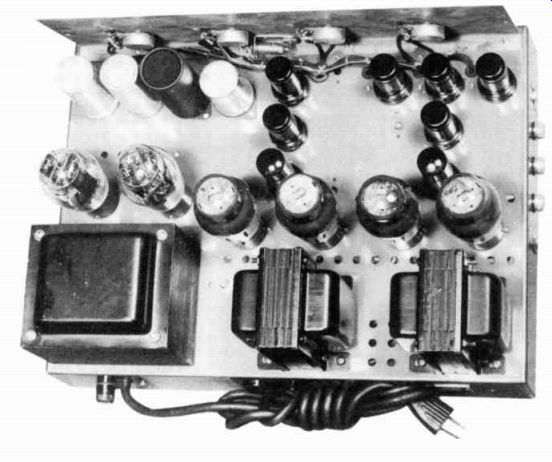
----------- Top chassis view of an amplifier unit. Note the accessibility
of the tubes for removal and replacement. Courtesy Stromberg-Carlson Co.
The tube of Figure 3A has a four pin base, a bottom view of which is shown in Figure 3C. Two of the pins are of large diameter and, starting at the left larger pin, for identification they are numbered 1, 2, 3, and 4, in a clockwise rotation. The internal circuits for this tube and base are indicated by the symbol of Figure 3E where the numbers at the ends of the electrode are those of the base pins to which they connect.
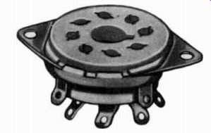
------------- A typical octal socket. Note the large hole in the center
with a keyway. This permits a tube to be placed in the socket in one position
only. Courtesy Meissner Mfg. Div. Maguire Industries, Inc.
The circuit in which the tube is used includes a receptacle, called a socket, which has openings of the same size and spacing as the pins on the tube base. Insulated from each other, these openings are metallic and connected permanently to the circuit wires.
Thus, when the tube base is inserted in the socket, the circuits are connected to the electrodes inside the envelope.
Although its construction is similar, the tube of Figure 3B is shown fitted with an eight pin or octal base, a bottom view of which is shown in Figure 3D. Here the pins are of equal size and spacing around a central post with a raised key. Starting to the left of the key, the pins are numbered from 1 to 8 in a clockwise direction. The schematic symbol of Figure 3F shows the pins to which the various electrodes are connected.
For this particular tube, pins 1, 4 and 6 are not used and may be omitted from the base. However, the positions of the remaining pins are not changed.
FUNCTION OF THE GRID
As explained for the diode of Figure 1, the flow of electrons from emitter to plate can be con trolled to a certain extent by varying the plate voltage or the emitter-temperature. With the exception of the rectifying action, these control methods have very limited applications.
A grid like that of Figure 2, placed between the emitter and plate, provides a much more effective method of controlling plate current. All electrons attracted to the positive plate pass between the turns of the grid coil. however, since like electric charges repel, a negative voltage on the grid repels the negative electrons and tends to force them back to ward the emitter. This repelling action varies with the negative grid voltage which therefore controls the number of electrons which reach the plate. Since these electrons constitute the plate current, it is controlled by the grid voltage.
To illustrate this control action, in Figure 4 the grid is represented as a venetian blind while the emitter and plate are similar to those in Figure 1. For simplicity, the external circuit connections are omitted, but we will as assume that the tube electrodes are connected to proper voltage sources to provide a heated emitter, a negative voltage on the grid, and a positive voltage on the plate.
Figure 4A illustrates the condition that exists for some inter mediate negative grid voltage. In this case, the venetian blind grid is partly open so that some of the electrons are able to pass through the relatively narrow slits and continue to the plate, while others are blocked and "bounce" back.
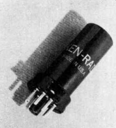
----------------- An octal that the tube has a center aligning pin so
prongs will enter the proper socket openings. Courtesy General Electric Co.
In Figure 4B, the wide open venetian blind indicates the negative grid voltage has been reduced, and practically all of the electrons are able to pass through to the plate, until with zero grid voltage, the action is essentially the same as explained for the diode of Figure 1.
Although the action of the grid does not increase the number of emitted electrons, its negative voltage can be increased sufficiently to completely block them from the plate as pictured in Figure 4C. This condition is known as PLATE CURRENT CUTOFF. Actually, the grid structure does not physically open and close like the venetian blind, but electrically its effect is the same. The varying force of repulsion which the changing negative grid voltage exerts on the negative electrons, controls the number that reach the plate. The more negative the grid voltage, the more the electrons are repelled, and fewer are the number that can pass.
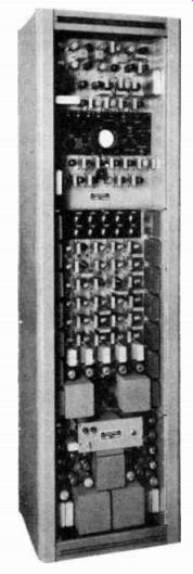
--------------- Over 90 tubes are used in this synchronizing generator
to generate the pulses required for television camera operation. From DeVry
Tech. Labs.
To produce the actions illustrated in Figure 4 a complete circuit is shown in Figure 5, where the tube V1 is indicated by the symbol of Figure 3F. The external plate circuit extends from the plate, through the plate supply battery Ebb from positive to negative, and over to the cathode. In this circuit, the direction of electron flow, which constitutes the plate current, is in the direction indicated by the arrow heads.
The grid connects to the sliding contact of potentiometer R, which in turn is connected across the grid supply battery Err. Since the midpoint of this battery connects to the tube cathode, the grid can be made more negative than the cathode by moving the slider to ward the "-" end of the battery, or more positive by moving it toward the " + " end.
When the slider is in the extreme right position the grid is at the maximum positive voltage and the plate current is maximum. In contrast, when the slider is moved to the extreme left, the grid reaches a maximum negative and the plate current drops to minimum.
ANY VARIATION OF VOLTAGE APPLIED TO THE GRID CIRCUIT CAUSES A CORRESPONDING VARIATION OF PLATE CURRENT. It is this control of the grid voltage on the plate circuit current that is used in so many electron circuits. However, to fully understand just what occurs, certain operation characteristics of an electron tube have to be considered.
TRIODE CHARACTERISTICS
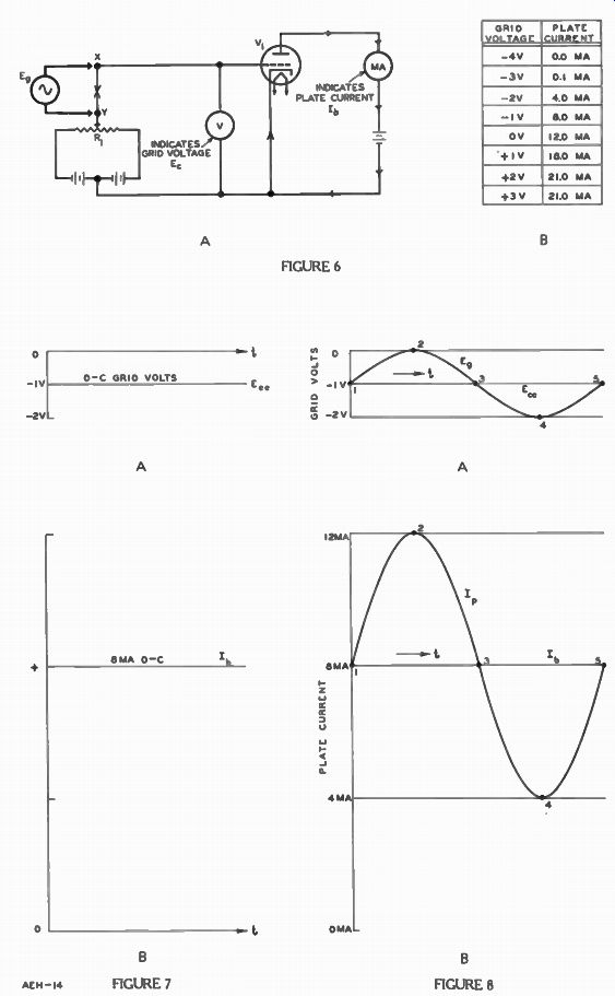
To understand the detailed performance of triode, and for that matter all electron tubes, it is very helpful to make voltage and current readings. For instance, when plate current readings are recorded for each control grid voltage reading as shown in Figure 6B, if the other electrode voltages remain constant, it is possible by examining this chart to learn more about the triode.
The readings for grid voltage and plate current for any particular tube type are obtained by means of a circuit like the one shown in Figure 6A. As its sole purpose is to maintain the cathode at the proper operating temperature, the heater circuit and supply are not included in the dia gram. However, assume that all the circuits are complete and that the tube is in normal operating condition.
The rest of the circuit is like that of Figure 5, but arrangements are included to connect an alternating voltage Eg between the slider of R, and the grid of the tube. Also, a voltmeter V is connected between the grid and cathode to indicate the grid voltage and an ammeter MA is connected in series with the plate to indicate the plate current.
By moving the slider of potentiometer R1 one way or the other, several values of positive and negative voltage are applied to the grid as indicated by the volt meter. For each position of the slider, the resultant plate currents are indicated by the milli ammeter and the readings of both meters are tabulated in the chart of Figure 6B. According to this chart, for the particular tube under test, the plate milliammeter reads zero when the R1 slider is adjusted so that the voltmeter reads 4 volts negative. SINCE THE PLATE CURRENT IS ZERO, THE GRID VOLTAGE AT THIS POINT IS CALLED THE Cut off bias. When R1 is adjusted so that the grid is 3 volts negative, the milliammeter reads .1 ma.
With the grid 2 volts negative the plate current is 4 ma, for 1 volt the plate current is 8 ma and for zero grid voltage the plate current rises to 12 ma.
Normally, the grid is maintained negative with respect to the cathode, but in certain applications, it is permitted to become positive for at least a portion of the time. Therefore, to complete the picture of a tube's performance, several readings are included for positive grid voltages.
With the grid at +1 volt the milliammeter reads 18 ma; with +2 volts on the grid, the plate current reading is 21 ma; and for this particular tube, +3 volts on the grid still indicates 21 ma. In fact, any further increase in positive grid voltage does not in- crease the plate current. Since this indicates that all of the electrons emitted by the cathode, except for the few attracted to the positive grid, are reaching the plate, it is called saturation.
---------- Sub-miniature tubes are very small. This hearing-aid tube is
only 3/4 in. long and 34 in. in diameter. Courtesy Sonotone Corp.
Thus, for all practical purposes, the operating range of the tube is from cut off bias to plate saturation. These are the extreme limits of the tube. Sometimes the tube may be operated exactly at cut-off bias and other times it may be operated at saturation. However, for most purposes it is operated between these two extremes.
By examining Figure 6B, we can see why it is desirable to operate about half way between these values. Note that for 0 volts on the grid the plate current is 12 ma, and changing the grid voltage to a negative 1 volt, the plate current decreases to 8 ma. Thus, a change in grid voltage of 1 y produces a change in plate cur-rent from 12 to 8 or 4 ma. Going from a negative 1 volt to a negative 2 grid volts, produces a change in plate current of 8 - 4 = 4 ma; changing the grid voltage another volt to a negative 3 volts, produces a current change of 4 - .1 = 3.9 ma.
Going to a negative 4 grid volts, cuts off the plate current. That is a 3 grid volt change only gives .1 - 0 = .1 ma instead of 4 ma change. Each of these first three steps of 1 grid volt produce approximately 4 ma change in plate current, but for the last situation, this no longer was true, nor is it true going from one positive grid voltage to another.
The range producing an equal plate current changes for equal grid voltages is where the triode usually is operated. As either a positive grid voltage is reached or cut-off bias is neared, the grid voltage does not vary the plate current by the same amount.
Therefore, a d-c voltage some where near the center of this range is applied to the triode grid for best results.
TRIODE AMPLIFICATION
To demonstrate the typical operation of a triode, let's pick a grid voltage of -1 volt. According to Figure 6B, this permits a d-c plate current of 8 ma through the tube. Figure 7A represents the grid voltage in the vertical direction for different intervals of time along the horizontal line.
Figure 7B is the d-c plate current with the grid at -1 volt for the same time intervals. The vertical distance from the line represents the values of grid voltage in Figure 7A and the plate current in Figure 7B. Going back to the circuit of Figure 6A, if the wire between points X and Y is removed and the a-c source Eg connected as shown there will be two voltages connected in series in the grid cathode circuit of the tube V,. Thus, the total grid voltage consists of a d-c component, supplied by the E„,. battery and an a-c component supplied by source Eg.
This is shown by Figure 8A. Here 1 volt a-c or Eg is added to the -1 volt for E, „ d-c. At point 1, their total is -1 volt since the a-c is zero and the d-c is -1 volt.
At point 2, their total is zero since
+ 1 and -1 d-c exactly cancel. At points 3 and 5, the grid voltage again is -1 volt, while at point 4, their total is -1 and -1 or -2 volts. , During one alternation, the a-c aids the d-c and the total voltage is equal to their sum. During the next alternation, the a-c opposes the d-c and the total voltage is equal to their difference. Thus, the grid voltage varies continuously above and below the d-c voltage.
This is a very common condition in tube grid circuits and the d-c or fixed voltage is called grid bias or C-bias. By definition, bias means a voltage or difference of potential between two electrodes of a tube. However, the term is used almost exclusively to refer to the fixed or d-c grid voltage.
Since THE CATHODE IS THE USUAL VOLTAGE REFERENCE POINT of an electron tube, and in most application the grid is negative with respect to the cathode, usually it is assumed that the grid bias is negative, and the a-c, applied in series with the grid bias is called the signal voltage.
The d-c grid bias, -1 volt for this example, determines the operating point of the tube. That is, depending upon its direction at any instant, the signal voltage either decreases or increases the negative grid voltage, and hence, swings about this operating point.
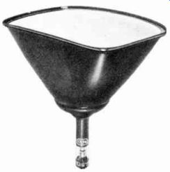
------------ A picture tube is a special type of electron tube. It has
a heater, cathode, and control grid in addition to other electrodes. Courtesy
Radio Corporation of Americo
At the same time the grid voltage is changing in Figure 8A the plate current changes as shown in Figure 8B by I„. All the points are identical in both Figures. At point 1, in Figure 8B, since the grid voltage is 1 volt, according to Figure 6B the plate current is 8 ma.
At point 2 in Figure 8B, the grid is now at 0 volts, or has become less negative. Not as many electrons are repelled and the plate current increases to 12 ma. At points 3 and 5, the current 1,, is at 8 ma. At point 4, the bias is -2 volts and the greatest repulsion occurs, so the plate current drops to 4 ma. A small change in grid voltage of 2 volts produces a plate current change of almost 8 ma.
Thus, as indicated by Figures 8A and 8B, the plate current variations have the same form as the grid voltage and so long as the circuit conditions are maintained, this action repeats itself during each successive cycle.
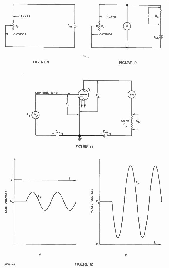
The action for the circuit in Figure 9 is similar to Figure 6A. Variable resistor R1 represents the resistance of tube V, and E., is the same in both Figures. As the arm of R, is moved toward the end marked "cathode" more resistance is placed in the circuit.
By Ohm's Law, a higher resistance divided into a constant voltage E., gives a smaller current.
In terms of the tube V, in Figure 6A, this is the same as increasing the bias and hence reducing the plate current.
By moving the arm of R, to ward end marked "plate" there is less resistance in the circuit, hence the current increases. Since this is the same action as provided by tube V, in Figure 6A when the bias is decreased and the plate current increases, a tube acts just like an automatic variable resistor. In fact, for many purposes, it is helpful to think of an electron tube as a variable resistor.
Figure 6A and the explanation in Figure 9 show how an electron tube can be used to control a current by a small voltage. Frequently it is necessary to control a large voltage with a small voltage. For this purpose we need to add a fixed resistance called the plate load resistor in the plate circuit as shown by RL in Figure 11. How this circuit works can be seen by using Figure 10 where R1 represents the triode and RL is the added fixed resistor. Moving the arm of R1 toward the plate is the same as decreasing the bias and it decreases the total resistance in the circuit. Again, the current increases and so the voltage across R, increases. A larger current times RL gives a higher voltage EL across RI: Moving the arm of R1 toward the cathode increases the total resistance of the circuit. The current therefore decreases and the small current through resistor RL results in a lower voltage EL across RL. Thus, as the grid voltage in Figure 11 changes, the plate current likewise changes. As the a-c signal on the grid goes positive the plate current increases and the voltage EL increases. As the a-c signal on the grid goes more negative, the plate current decreases, and the voltage across EL decreases. A "+" a-c signal on the grid decreases the bias and the voltage EL increases.
Actually the variations in the voltage EL across load resistor RL are larger than the voltage variations applied to the triode grid.
For example if the circuit in Figure 11 has the grid voltages and plate currents shown in Figure 6B when plate load RL has a resistance of 10,000 ohms, this variation can be determined by Ohm's Law. For 0 y on the grid the 12 ma of plate current produces .012 x 10,000 or 120 volts across RL. For -2 y on the grid 4 ma of plate current produces .004 x 10,000 or 40 volts across RL. Therefore a change of 2 volts on the grid produces a 120 - 40 or 80 volt change across RL and 1 volt on grid produces a 40 volt change.
At the same time that the voltage varies across RL it also varies on the triode plate.
In Figure 10 as the resistance of R1 is decreased, the current increases and EL increases. Thus, since Ebb is constant and EL is increased, there is less voltage across R1 . R1 represents the tube, and so there is less voltage across the tube V1 in Figure 11.
On the other hand as the resistance of R1 is increased, the current decreases and EL decreases.
Since Eh,, is constant and EL is decreased, there is more voltage across R1 . That is the plate voltage is increased.
The small a-c signal on the grid controls a large a-c voltage on the plate. Figure 12 shows the relationship between the voltages for a complete cycle. The horizontal line E, in Figure 12A indicates the d-c bias and a-c or Eg goes above and below this reference.
In Figure 12B the horizontal line indicates the plate voltage E,, during the time d-c bias is applied and so the a-c plate voltage E, due to the a-c signal on the grid riding goes above and below this line.
During the positive alternation of the grid signal, the plate voltage makes a negative alternation, while during the negative alter nation of the grid signal, the plate voltage makes a positive alternation. Moreover a small a-c grid signal controls a large a-c signal on the plate and this is referred to as the amplification of the tube. So long as the plate load RL is a resistor, the a-c voltage on the plate is exactly inverted with respect to the a-c grid voltage.
It is this ability to amplify that makes the electron tube so useful.
For example, light rays, too weak to do much, can generate a voltage in a photocell. This weak voltage is amplified by tubes until large enough to operate a bell, relay, or motor. Or, a pressure too weak to turn a valve can be converted to a voltage and the voltage amplified until strong enough to actuate the solenoid that closes the valve.
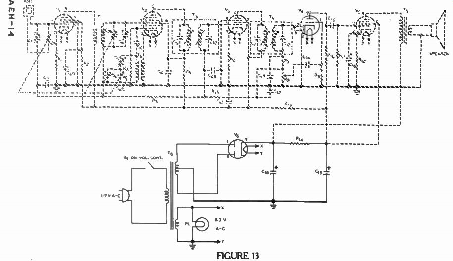
The antenna for the radio in Figure 13 is a conductor that intercepts very weak magnetic fields radiated by the broadcast station.
Naturally these magnetic fields induce very small voltages in the antenna. Therefore, one of the important functions of the tubes in a radio is to build up this weak signal to a useful voltage.
But amplification isn't the only function for these tubes, and di odes and triodes are not the only tube types. Although Tube V. is a triode tube with two added electrodes for other independent purposes and Vg has two diodes, all of the other tubes in Figure 13 have added electrodes which affect the main operation of these tubes. In order to understand fully how this radio works we must know why these electrodes are needed and how they function. And so, we describe these multi-electrode tubes in the next lesson.
IMPORTANT DEFINITIONS
AMPLIFICATION--Referring to the ability of an electron tube to make a large a-c plate signal from a small a-c grid signal.
CUTOFF BIAS--That d-c voltage which applied to the tube grid, reduces the plate current to zero.
GRID-A control electrode, usually in the form of a spiral wire or mesh, placed between the cathode and plate of an electron tube.
GRID BIAS-(E, ) -[GRID BIH uhs]--A d-c voltage used to maintain the grid of an electron tube negative with respect to the cathode and thus establish the operating point. Known also as C bias.
OCTAL BASE-[AHK tuhl BAYS]--An electron tube base having a central part plug and aligning key, and eight equally spaced positions for the connecting pins.
PLATE LOAD RESISTOR--As used in this lesson, a resistor in the plate circuit through which current passes thus developing the output signal voltage.
SIGNAL- (Eg)-The a-c voltage applied to the grid of an electron tube.
TRIODE-[TRIGH ohd]-A 3-electrode tube containing a cathode, grid, and plate.
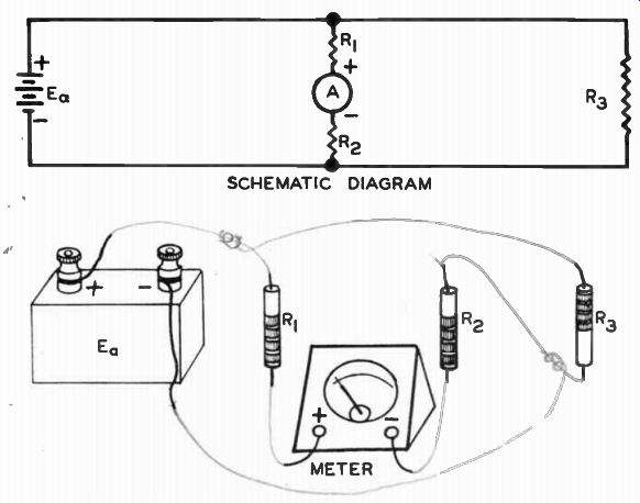
WORK DIAGRAM
By pencil lines, connect the pictorial units as indicated by the schematic diagram.
------------
When you have finished, check with the answer on the back of the fold-out sheet.
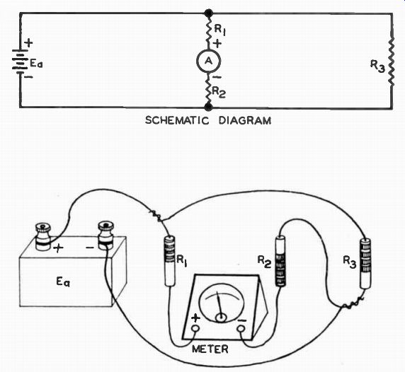
--------------- WORK DIAGRAM SOLUTION
--------------
--------------
---------------
--------------
FROM OUR Director NOTEBOOK
THE EIGHTH MISTAKE OF MAN
A well-known writer advises that there are seven mistakes Man is prone to make:
1. That individual advancement can be made by crushing others.
2. Worrying about things which cannot be changed or corrected.
3. Insisting that a thing is impossible because we ourselves are unable to accomplish it.
4. Refusing to set aside trivial personal preferences in order that important cooperative benefits may be achieved.
5. Neglecting to develop mental refinement by the habit of cultural reading.
6. Attempting to compel other persons to believe and live as we do.
7. Failing to establish the habit of saving money.
AN EIGHTH MISTAKE
Allowing others to persuade us that we can get something for nothing.
Yours for success,
DIRECTOR