AMAZON multi-meters discounts AMAZON oscilloscope discounts
Lesson AEH-15A
ELECTRONS EXTEND VISION
A large ocean liner is being maneuvered through close quarters to its dock. On the ship's bridge, the officer in charge cannot see whether sufficient clearance exists at all points because of the great size of the boat.
To check at some remote section, he flips a switch and a view of the section appears on a screen before him. This view is provided by television equipment of the same type employed for entertainment purposes in the home.
Little does the average person realize that there are many applications of television other than entertainment. Uses by industry include observation of hazardous operations carried on by remote control from a safe distance, three dimensional television facilitates remote control of intricate manipulations, and medical schools employ color tele vision to demonstrate the details of important surgical techniques to large classes.
Fundamentals
MULTI-ELECTRODE TUBES
Contents
Interelectrode Capacitance Tetrodes Secondary Emission Pentodes Beam Power Tubes Combination and Special Purpose Tubes Tube Classification Maximum Tube Ratings
It is well for a man to respect his own vocation whatever it is, and to think himself bound to up hold it, and to claim for it the respect it deserves.
-Charles Dickens
MULTI-ELECTRODE TUBES
Patented in 1907, the triode type of electron tube was designed for use as a sensitive detector of Wireless Telegraph signals, the only form of radio in use at that time. The triode operated success fully in its intended application, but it was some time before the amplifying and a-e generating capabilities of the tube were even suspected.
However, since then, intensive studies of its action have disclosed many new applications as well as characteristics both desirable and undesirable. By adding electrodes and modifying the internal structure, designers have developed several hundred types of electron tubes, each of which is adapted especially for some particular application. Therefore, to fully understand the operation of many electron circuits, it is necessary to know the reason for these modifications.
INTERELECTRODE CAPACITANCE
In the lesson on capacitors it was pointed out that when two conducting surfaces are separated by an insulating material, they form a capacitor. Two parallel wires form a capacitor, and the capacitance depends on the length of the wires, the distance, and the type of material between them.
Thus the electric power, telephone, and telegraph wires which are mounted on poles possess capacitances, however, because of the relatively large spacing between the wires, it is too small for normal considerations.
In any triode tube, the cathode, grid, and plate form a system of capacitors, with each electrode acting as a plate. Thus, a small but definite INTERELECTRODE CAPACITANCE exists between the cathode and grid, the grid and plate, and the plate and cathode.
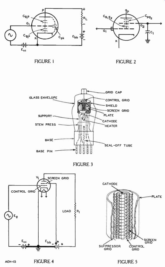
In the triode tube symbol of Figure 1, dotted lines represent these capacitances between electrodes.
The capacitance between grid G1 and plate P is labeled Cop; between grid G1 and cathode K is ; and Cpk is between plate and cathode.
Generally, the capacitance between the grid and plate has the greatest effect on the operation of a triode. In the previous lesson it was explained that a signal applied to the grid causes changes of plate current which produce variations of voltage drop across a load resistor.
Voltage variations on the plate produce charge and discharge of the interelectrode capacitance between plate and grid. The resulting displacement currents produce voltage drops across any resistances in the grid to cathode circuit. Consequently some of the voltage in the plate circuit appears in the grid circuit by the "coupling" action of the interelectrode capacitor C„,,. Due to the small capacitance, at low frequencies this coupling action is not noticeable, but for high frequency alternating currents it becomes too serious to ignore.
TETRODES
In order to reduce the grid to plate capacitance for tubes used in certain high frequency circuits, another grid is inserted between the control grid and the plate.
Since it screens the grid from the capacitive effects of the plate, it is referred to as the screen grid.
An electron tube with four active electrodes is known as a tetrode.
The emitter is counted as one electrode whether heated directly or indirectly.
As shown in the tetrode tube symbol of Figure 2, the addition of the screen grid changes the grid to plate capacitance C,„ into two series capacitances, the screen grid to plate capacitance and the control grid to screen grid capacitance Cgig.,.
The total capacitance between the control grid and plate is essentially the same as before, however its effect is greatly reduced, by connecting a large capacitor C1 from the screen grid to ground.
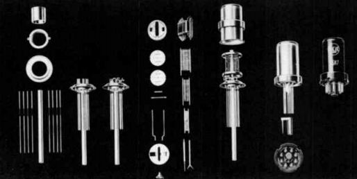
--------------- Structural parts of a typical metal tube. Looking from
left to right you will see the tube stem parts, the tube stem, the tube mount
parts, the tube mount, the evacuated tube, and the finished tube. Courtesy
RCA
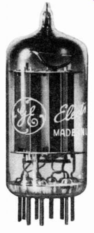
--------------- Surrounding the tube elements in this pentode, the perforated
metal cylinder is connected to the screen grid and helps to shield the plate
from the control grid. Courtesy General Electric Co.
To understand this reduction, two facts must be kept in mind: (1) capacitors C1 and C g1 g 2 are in parallel in most tube circuits, and (2) the current in parallel capacitors depends upon their individual capacitance.
C1 and Cg1g2, are in parallel since each one connects to the screen on one side and to the ground on the other. Although Cg1g2 does not connect directly to ground, it connects from the grid, through the grid circuit to ground in most circuits much like the grid circuit of Figure 4.
Parallel capacitors charge to the same voltage and the quantity of the charge in each capacitor is directly proportional to its capacitance. Also, on charge or discharge, the shift of electrons as they enter one plate and leave the other is called the displacement current. Hence, if capacitor C, has a capacitance 1000 times as large as C it accepts 1000 electrons of the - displaced current for every electron received by Cg,„.,. Therefore only one thousandth of the C„,; ., displacement current is displaced into the grid circuit by Cgig.,. Hence, the effect is too small to be harmful even at high frequencies.
As shown in the cutaway view of Figure 3, the mechanical construction of a tetrode is quite similar to that of the triode described in a previous lesson. All of the electrodes are mounted on wire supports embedded in the stem press and the wires for external circuit connections are carried down through the base pins.
The cathode surrounds the heater, and a grid surrounds the cathode. For identification, this grid is indicated as g, in the symbol of Figure 2 and labeled control grid in Figure 3. In this particular type tube, the control grid connection is brought out through the top of the envelope and terminates in an external grid cap.
However, for most tetrodes, the control grid connection is made through a base pin to form what is known as a "single ended" tube.
These will plug into the same octal or miniature sockets as the triodes.
Similar in construction, the screen grid is mounted around the outside of the control grid and the plate surrounds the screen grid. To provide additional isolation of the plate, the shield which surrounds it is connected electrically to the screen grid.
As indicated in the schematic diagram of Figure 4, normally the screen grid is operated at a positive voltage slightly less than the plate. In this case, a battery is used as the power supply, there fore, capacitor C1 of Figure 2 is unnecessary. The internal battery resistance is so low that it con ducts the C„g2 displacement current directly to the cathode and ground of the circuit.
Since the screen is positive with respect to the cathode, it at tracts the electrons much like the plate in a triode. However, due to its open structure, most of the electrons do not strike the screen but continue on to the plate. In fact, this attraction is so effective that the plate voltage variations produce only a small change in the plate current since a large number of the electrons attracted by the screen continue on to the plate for all positive plate voltages.
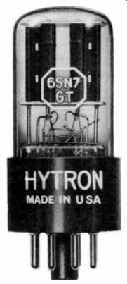
---------- Two complete triode units are mounted in this evacuated tube
to conserve space and material. Courtesy Hytron Radio and Electronics Co.
SECONDARY EMISSION
When electrons are emitted from the cathode they are attracted by the positive voltage on the plate. Thus the speed of the electrons increases progressively as they move from the cathode to the plate. Usually the electrons attain sufficient speed to dislodge one or more other electrons from the surface of the plate upon impact.
------------- This tube has three diodes and a triode en closed in the
some envelope. Courtesy General Electric Co.
This effect is called secondary emission and the released electrons are known as SECONDARY ELECTRONS. Secondary emission produces no difficulty in diodes or triodes because the positive plate attracts and eventually recaptures these electrons. However, in tetrodes the nearby positive screen grid attracts the electrons produced by secondary emission. As a result of this robbing effect, the plate current is reduced, and the signal output of the tube goes down.
PENTODES
To overcome the disadvantages of secondary emission in tetrodes, another grid is added between the screen grid and plate as shown in the cutaway drawing of Figure 5.
This third grid connects to the cathode or to some other point in the circuit which is negative with respect to the positive plate and screen grid.
The electrons which travel from the cathode to the plate are slowed down by the negative grid, nevertheless, they still have sufficient speed to travel through the openings in this third grid and onto the plate. Very few electrons are stopped and repelled back to the screen grid.
Due to the decreased speed of the electrons as they reach the plate, the secondary emission is reduced considerably. Even the secondary electrons which are emitted are repelled back to the plate by this negative grid. Thus, the added grid isolates the plate and the screen grid, and thereby greatly reduces the effects of secondary emission.
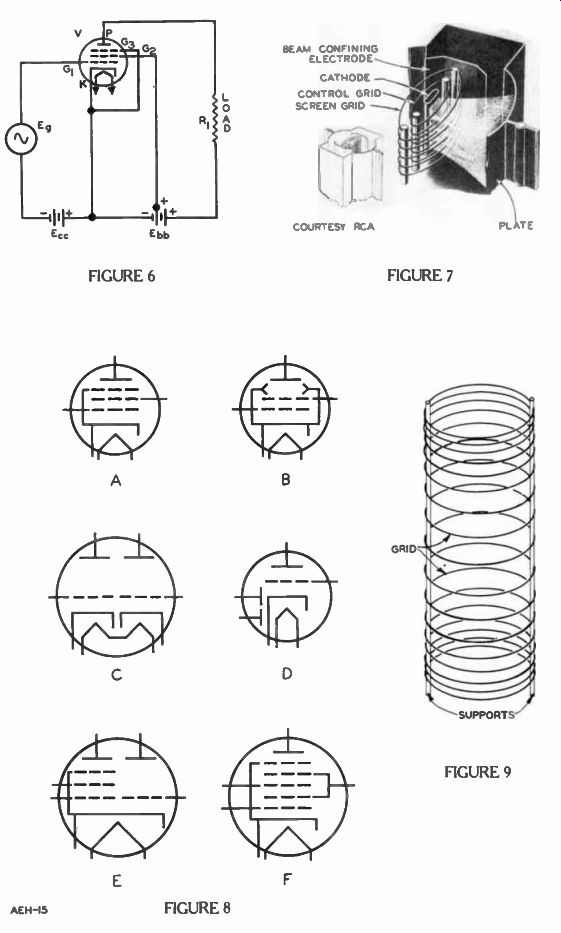
A tube containing five electrodes is called a pentode. The symbol and connections of a pentode are shown in Figure 6, and the various grids, indicated by the letters G1 , G,, and are numbered in the order of their positions outward from the cathode.
G, is called the suppressor grid -or "suppressor". Thus, in the pentode tube of Figure 6, the five electrodes are: the cathode "K", the control grid "G1 " the screen grid "G.,", the suppressor grid "G;", and the plate "P". Figure 6 also shows the connections of a simplified pentode tube circuit. The suppressor grid G3 is brought out to a separate connection or base pin, which permits circuit variations where necessary. However, many pentodes are built with the suppressor grid connected to the cathode inside the envelope.
BEAM POWER TUBES
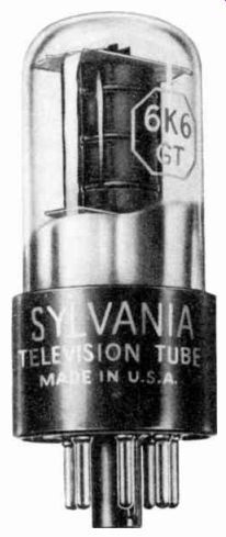
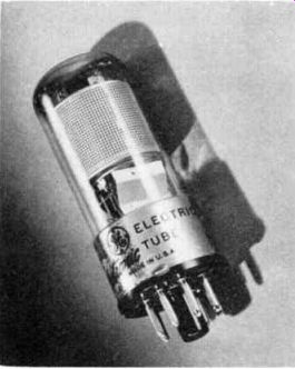
------------- The mirror-like finish on the inside of the envelope is
due to the deposit of the getter on the glass after it has been gashed. Courtesy
Sylvania Electric Products, Inc.
Although the action of the pentode suppressor grid has an ad vantage in that it reduces the effect of secondary emission from the plate, it also has some disadvantages. Since it is located between the screen grid and the plate, it is an obstruction in the path of the electrons that travel from the cathode to the plate. To minimize this obstruction, it is made of an open wire network or spiral, but then its repelling action on the secondary emission electrons is not uniform over the entire plate area. This uneven action results in distortion of the signal and limits the power that the tube can deliver.
To overcome these difficulties and thus provide considerably higher current-carrying capabilities than either the tetrode or pentode, the beam power tube has been developed. The basic construction of a beam power tube, shown in Figure 7, includes a cathode, control grid, screen grid, "beam-confining electrodes", and a plate. In some models a suppressor grid also is included.
By connecting these beam forming plates to the cathode, a negative voltage is placed on the two beam-confining electrodes.
Since like charges repel, these electrodes repel the negative electrons and compress them into beams as they travel from the cathode to plate. The flattened cathode not only gives a larger emitting area in the direction of the beams but aids in forming them to produce a higher plate current change for a small grid voltage change.
Suppressor action is obtained-- by making the distance between the screen grid and plate much larger than the distances between the other electrodes. With this increased distance and the beam forming action, a large number of electrons appear in this space and create a dense space charge. To further crowd the electrons, often the plate is operated at a voltage lower than the screen grid, there by slowing down the electrons and bunching them closer together. Due to its negative charge, this dense beam of electrons re pels the secondary emission electrons back into the plate. Hence, suppressor action is obtained without having a metal obstruction in the electron path.
Another feature of the beam power tube is the location of the screen grid in the "shadow" of the control grid. That is, the screen grid wires are placed directly in line with the control grid wires so that, as the electrons pass through the grid openings, they travel in sheets and very few are able to strike the screen grid.
Because of this arrangement, the screen grid current is low, and considerably higher currents can be produced in the plate circuit without overheating the tube.
Beam power tubes are represented in circuit diagrams by the symbol of either Figure 8A or 8B. In every type, the beam-confining plates are connected internally to the cathode. Therefore, external circuit connections are made to the cathode, control grid, and plate as in a tetrode. In fact, these tubes often are referred to as "beam power tetrodes".
COMBINATION AND SPECIAL PURPOSE TUBES
To conserve space and to re duce cost without sacrificing performance, it is common practice to combine the elements of two or more complete tubes in one envelope, and to mount the combination on a single, standard base.
Some of these combinations use a common cathode, while in others separate cathodes are provided.
One such combination is the DOUBLE TRIODE, shown by the symbol of Figure 8C. The two triodes are electrically independent of each other, and the physical construction and location of the various elements are such that both can operate without interfering with each other. Other examples of combination tubes are the DUO DIODE-TRIODE of Figure 8D and the TRIODE-PENTODE of Figure 8E. In both of these types a single cathode is used.
------------
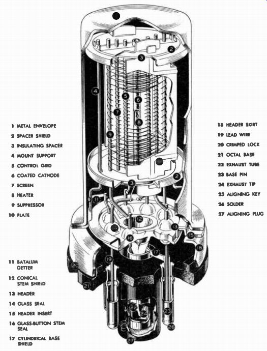
1 METAL ENVELOPE 2 SPACER SHIELD 3 INSULATING SPACER 4 MOUNT SUPPORT 5 CONTROL GRID 6 COATED CATHODE 7 SCREEN 8 HEATER 9 SUPPRESSOR 10 PLATE
11 BATALUM GETTER 12 CONICAL STEM SHIELD 13 HEADER 14 GLASS SEAL 15 HEADER INSERT 16 GLASS-BUTTON STEM SEAL 17 CYLINDRICAL BASE SHIELD 18 HEADER SKIRT 19 LEAD WIRE 20 CRIMPED LOCK 21 OCTAL BASE 22 EXHAUST TUBE 23 BASE PIN 24 EXHAUST TIP 25 ALIGNING KEY 26 SOLDER 27 ALIGNING PLUG
A cutaway view of an octal type pentode with o metal envelope. Courtesy Radio Corporation of America
-----------------------
In addition to these combinations, there are also a number of special purpose tubes which were developed for specific functions.
For example, the PENTACRID CON VERTER shown in Figure 8F is a special purpose tube which contains five grids, hence the name pentagrid. Some of the grids are connected internally, while others are brought out for external connections. The descriptions of special purpose tubes are not included here, but are postponed until later lessons, since the actions of these tubes can be explained more readily when their specific applications are under stood.
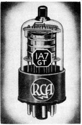
----------- This pentagrid converter contains five grids in addition
to a plate, cathode, and heater. Courtesy Radio Corporation of America.
TUBE CLASSIFICATION
Electron tubes are classified in many ways according to their structure, the number of elements, type of base, type or shape of the envelope, operating characteristics, or their use in a circuit.
One method of classification is based on the number of electrodes which the tube contains. Examples are found in the naming of the diodes, triodes, tetrodes, and pentodes already described. The same method is used in classifying other tubes such as those containing six elements, called "hex odes", those with seven elements are "heptodes", and those with eight elements are called "octodes". These prefixes come from Greek words signifying the numerals 2 to 8 as follows:
2-Di 3 -Tri 4-Tetra 7-Hepta 8-Octa 5-Penta 6-Hexa
A second method of classification of tubes is in accordance with their use such as "rectifier", "amplifier", "detector", and "cathode ray".
Diodes, triodes, tetrodes, pentodes, and beam power tubes all can be found in a variety of tube envelopes and bases. Hence, they are designated also as "miniatures", "octals", "lock-ins" or "loctals", or "metal tubes". Sometimes, tubes are referred Éo as "vacuum" or "soft" to designate their internal condition.
Vacuum tubes are those which have been highly evacuated of air before they are sealed. To increase the degree of vacuum, a material that vaporizes easily is added before the tube is sealed and then "flashed" by heating after the sealing operation is completed. When the material vaporizes, it absorbs the residual gases to form a more perfect vacuum.
The vaporizing materials, called "getters", are compounds of magnesium or barium. In fact, the mirror-like surface inside some glass tubes is due to a film of the getter deposited on the inside of the envelope when the tube is flashed.
Soft tubes are not fully evacuated, but have gas left in them, either accidentally or purposely added to obtain certain desired operating characteristics. Gas filled diodes are used in rectifier circuits, while gas-filled triodes and pentodes are employed in control circuits of electronic equipment.
Another type of tube classification comes from the amplification characteristic of the tube which was described in the previous les son. The Greek letter mu (p) is used to indicate how many times the change of plate voltage is larger than the change in grid voltage causing it. When the control grid wires are placed close together with very small spacing between them, changes in grid voltage have a large effect on the plate current. This type is called a HIGH-MU tube.
On the other hand, if the grid wires have a large separation, it will have less control over the plate current. Hence, this type is a LOW-MU tube. For the same reasons, a MEDIUM-MU tube has a medium spacing of the control grid wires.
When a large signal is applied to the grid of a high-mu tube, the negative peaks cause the plate current to be cut off. This action produces a distorted output, an undesirable feature that has been overcome by the unequal spacing of the grid wires. As shown in Figure 9, the grid wires have open spacing at the center and close spacing at the ends.
When a weak signal is applied to the tube, the effect of the unequal spacing of the grid is essentially the same as with equal spacing. However, as the grid becomes more negative, the plate current near the ends is cut off.
Then the current is dependent on the electron flow through the open spacing, and an extremely large negative bias is necessary to cut off the plate current entirely.
Some tubes have high-mu properties at low negative grid voltages and low-mu properties at high negative voltages. For this reason, this type of design provides what is called a VARIABLE MU tube. It is known also as a REMOTE CUTOFF tube since a large negative voltage is necessary to cause the plate current to cut off.
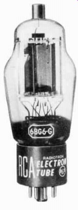
------------- This beam power tube is capable of con ducting large currents.
Courtesy RCA
In contrast, the high-mu tube is referred to as a SHARP CUTOFF tube.
MAXIMUM TUBE RATINGS Proper operation of electron tubes requires that certain maximum ratings be observed. When these ratings are exceeded, the life of the tube is shortened. For example, one important rating is the MAXIMUM PLATE DISSIPATION. This rating in watts indicates the maximum electric energy that can be converted into heat and dissipated safely and continuously by the plate. This energy conversion takes place when the electrons bombard the plate at high velocity.
-------------
REFERENCE PLANE OXIDE COATED CATHODE HEATER ANODE GRID
GRID RING SUPPORT
-CYCLINDER CATHODE RING HEATER BUTTONS
This triode has a very unusual construction to make it shock resistant and suitable for ultra high frequency amplifiers. Notice how close the plate or anode is to the cathode. Courtesy of General Electric Co.
------------
Another maximum rating is the PEAK HEATER-CATHODE VOLTAGE in tubes having a separate cathode terminal, and is used where high voltages are applied between the heater and the cathode. This rating indicates the highest voltage that can be applied safely between the heater and the cathode without breaking down the insulation.
No matter how carefully these maximum ratings are observed, electron tubes do become defective. Typical faults are: the heater breaks, two electrodes touch, the cathode loses its electron emission capability, or gas develops in the tube vacuum. All of these can cause defective or no operation. In fact, since the electron tube is the most fragile of the electronic components, tubes are suspected first when the equipment fails to function properly.
Frequently the faulty tube can be located by touch or sight. A glass tube may have an extra heavy blue glow indicating that it is gassy, or sparks or a red glow about the plate or screen indicate a short. A light tapping of the tube may produce noises or intermittent operation due to loose electrodes. Glass and metal tubes that remain cold after the rest of the tubes are hot may have an open heater. Likewise, a tube that gets too hot might have an internal short. However, be careful; many rectifiers and beam power tubes normally operate too hot to handle. More than a light, quick touch will give a bad burn.
Of course, all of these symptoms can be produced by other causes; it just happens that the tube is most often at fault, there fore, it pays to check these first.
Replace the tube with one of the same type known to be good.
Then if the fault remains, trouble is somewhere else. How these other troubles can be located with a minimum use of time and effort are described later in your training program.
The electronics of today would not be possible without electron tubes, for they are the very heart of the electron circuits. So the in formation, given in this lesson is extremely important. In the advance assignments of this training program, these tubes will be applied to various circuits the action of which depends on how the tube functions.
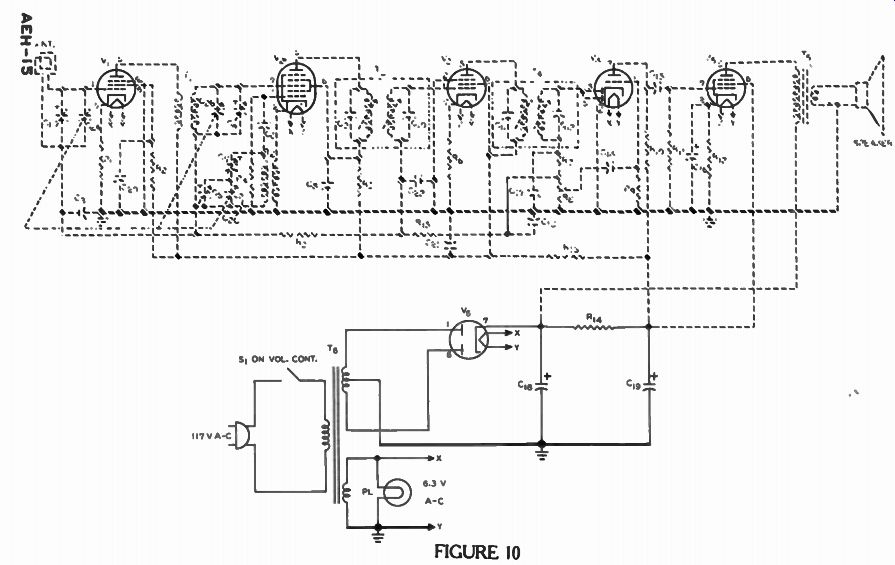
In Figure 10 is our radio circuit again. Since their structure has been described, the tube symbols now are black. Tubes V1 and V3 are the same as that tube in Figure 6 which is a pentode. Tube V., is the same as the pentagrid converter shown in Figure 8F. Tube V4 is identical to that shown in Figure 8D which is a duo diode-triode. Tube V3 is a beam power amplifier using the same symbol as found in Figure 8A. Tube Vfi is a full-wave rectifier described in an earlier lesson on power supplies.
In the next lesson, some of the basic actions in amplifier circuits are described such as methods for developing bias and how the signal is passed from one stage to another. In fact, the entire action of the circuit for the triode section of V4 and the beam power tetrode V5 are described in the next lesson.
IMPORTANT DEFINITIONS
BEAM POWER TUBE-An electron tube constructed with special beam-confining electrodes which concentrate the electrons into beams, and provide high current-carrying applications.
PENTAGRID-[PEN tuh grid]-An electron tube containing five grids.
PENTODE-[PEN tohd]-An electron tube with five active electrodes.
SCREEN GRID-A grid placed between the control grid and plate of an electron tube to screen the control grid electrically from the plate.
SECONDARY EMISSION-Electrons liberated from the plate due to the impact of the electrons arriving from the cathode.
SUPPRESSOR GRID-A grid placed between the screen grid and plate in a tube. Often it is connected to the cathode, and its function is to suppress the secondary emission by repelling the dislodged electrons, thus forcing them back into the plate.
TETRODE-[TET rohd]-An electron tube with four active electrodes.
WORK DIAGRAM
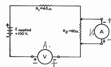
------------ Ammeter scale
0-2 ampere
Voltmeter scale
0-100 volts
(a) What is wrong with the above diagram?
(b) Using the same symbols, draw the circuit correctly so that V measures the voltage across R. and A measures the current in It...
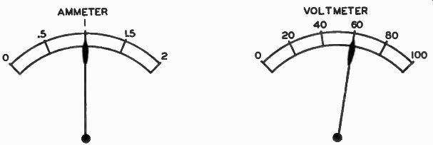
(c) On the scale faces of the ammeter and voltmeter, show the approximate position of the meter pointer for correct measurements.
AMMETER VOLTMETER
------------ When you have finished, check with the answers on the back
of the fold-out sheet.
WORK DIAGRAM SOLUTIONS
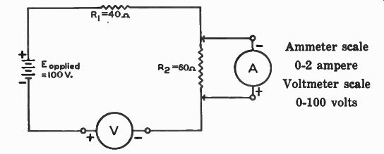
------------
Ammeter scale
0-2 ampere Voltmeter scale
0-100 volts (a) What is wrong with the above diagram?
The voltmeter and ammeter are in exchanged positions. The polarity of the meters terminals are reversed.
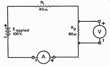
------------
(b) Using the same symbols, redraw the circuit.
R1 (c) On the scale faces of the ammeter and voltmeter, show the approximate position of the meter pointer for correct measurements.
----------
------------
-----------
------------
FROM OUR NOTEBOOK
Initiative
Elbert Hubbard once said: The world bestows its big prizes, both in money and honors for but one thing. And that is Initiative. What is Initiative? I'll tell you: It is doing the right thing with out being told. But next to doing the thing with out being told is to do it when you are told once. Those who can do this get high honors, but their pay is not always in proportion. Next, there are those who never do a thing until they are told twice: such get no honors and small pay. Next, there are those who do the right thing only when necessity kicks them from behind, and these get indifference instead of honors, and a pittance for pay. This kind spends most of its time polishing a bench with a hard-luck story. Then, still lower down in the scale than this, we have the fellow who will not do the right thing even when some one goes along to show him how and stays to see that he does it; he is always out of a 'lob, and receives the contempt he deserves, unless he happens to have a rich Pa, in which case Destiny patiently awaits around the corner with a stuffed club. To which class do you belong?
Yours for success,
-DIRECTOR