AMAZON multi-meters discounts AMAZON oscilloscope discounts
Lesson AEH-13 B
ELECTRONS REPRODUCE PHOTOGRAPHS
The press photographer rushes from the newspaper office to a distant scene, quickly snaps a number of photos and develops them on the spot. Then, instead of rushing them back to the office, he opens what appears to be a portable typewriter case, al though actually it is a compact facsimile transmitter. With a photo placed on a cylinder, the newspaper office is phoned, and then with the telephone set on a holder provided, the transmitter is turned on. The signal is sent over the telephone wires to the office where a facsimile receiver reproduces the photo.
Known variously as "tele-photo", "wire photo" or "radio-photo", facsimile also is used to convey pictures of events which occur in remote parts of the world. Business concerns such as banks, law offices, distributing houses, department stores, railroads and many others, use facsimile for rapid transmission of photographs, diagrams, or copies of important papers, containing necessary signatures.
Fundamentals
ENERGY CONVERTERS
Contents
Cells Primary Cells Wet Cells Dry Cells Secondary Cells Lead-Acid Cells Edison Cell Batteries Water Pumps in Parallel Electric Cells in Parallel Water Pumps in Series Electric Cells in Series Battery Capacity Applications of Induction Headphones Loudspeakers Loudspeaker Cone
Cone Suspensions Speaker Field Magnets Baffles Microphones
Reading is to the mind what exercise is to the body.
As by the one, health is preserved, strengthened and invigorated: by the other, virtue (which is the health of the mind) is kept alive, cherished and confirmed.
- Addison
ENERGY CONVERTERS
Today practically everyone has heard sounds pour out of a radio, the modern phonograph, or the sound system at a movie and many people have seen the picture on the television screen. Yet, few stop to think what actually is happening: that electricity is converted to sound energy or light as a picture on the screen are accepted as a matter of fact.
Actually energy converters are very important to every electronic system. Electricity by itself is almost useless; it is needed to produce or control such things as motion, sound, heat, and light.
Converters must be used to change chemical activity, light, heat, or mechanical energy to electricity or eventually convert electricity to one of these forms again.
The microphone that picks up sound, the photocell that detects light rays, and the thermocouple that detects heat are just a few of the very many energy converters used in electronics. Moreover, each of these has many uses. For example, to name but four applications of the photocell, it is used to pick up sound from movie film, open doors, set off burglar alarms, and count objects on a conveyer.
In fact, we had energy converters in our earlier lessons. We showed how electromagnetism was used by an electric current to ring a bell, and, to produce an electric current by a rotating loop.
In one, electric energy is converted to the mechanical energy of the moving bell clapper and in the other the mechanical energy of the rotating loop was converted to electricity.
At this time, rather than consider all of possible applications that energy converters are used for, we shall describe only those most likely to be found in a radio receiver. The others can be explained better when we describe their application.
CELLS
Many of the portable radios in use today have some provision for battery operation. In addition, radios usually are almost standard equipment for the car. These too, operate from a battery. In either case, these batteries are made up of smaller units called cells.
In the very first lessons of our training program we used cells as a source of electric current for the circuits. At that time no mention was made of their internal construction. Actually cells are energy converters that use chemical action to produce electricity, and these cells belong to one of two basic types: In the primary cell once the material is consumed by the chemical action, the cell is done for and must be replaced.
In a secondary cell, the material can be restored to its original condition by forcing a current through it in the opposite direction. That is, it can be recharged.
The flashlight battery is a good example of primary cells and car batteries are made up of secondary cells.
PRIMARY CELLS
A primary cell consists of two different metals, called electrodes separated by a solution known as an electrolyte. The electrolyte is always a liquid. However in DRY CELLS, this liquid is absorbed in a porous material just as a blotter soaks up ink, so that the cell can not spill, whereas the liquid is free to pour from a WET CELL. Wet Cells
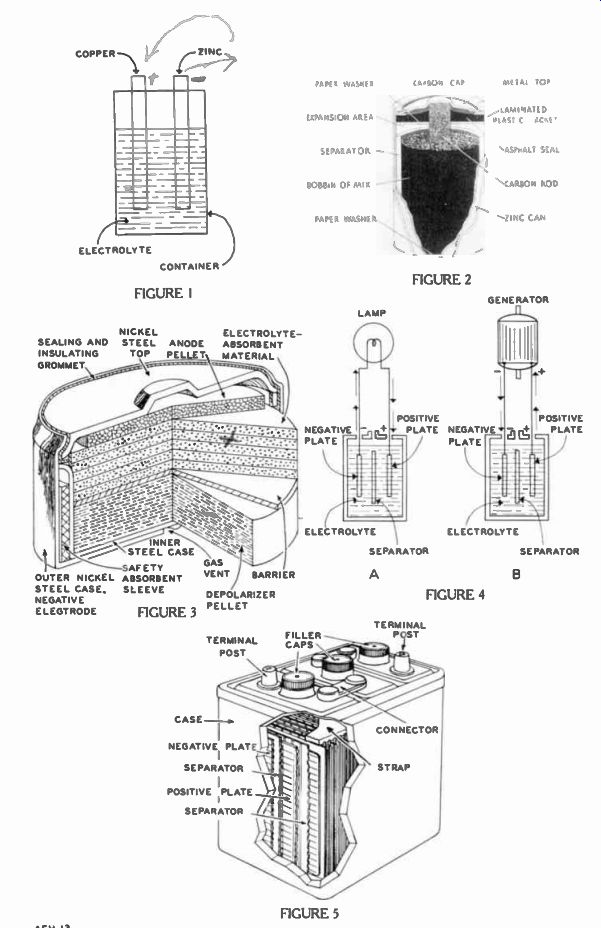
The basic arrangement of a wet cell is illustrated in Figure 1.
Here, one electrode is made of copper and the other of zinc, while the electrolyte is an acid solution. Dissolving slowly in the electrolyte, the zinc gives off positive zinc atoms. This action leaves an excess of electrons on the zinc electrode and so it is negative. At the same time, positive atoms created from the electrolyte remove electrons from the copper electrode, thus making it positive.
With the zinc electrode at a negative potential and the copper electrode at a positive potential, there exists a voltage between the two electrodes. Eventually, the chemical action between the electrolyte and zinc reaches a balance, that is, both have an equal number of charges, and the chemical action ceases.
However, if a lamp bulb connected to the battery or the battery is placed in an electric circuit, electrons flow outside of the battery from the negative zinc electrode, through the lamp and to the positive copper electrode.
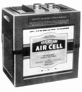
------------- A commercial cell used for supplying the current to heat
the filaments of radio tubes. Courtesy National Carbon Co.
As current is drawn from the cell, the zinc electrode is consumed until finally it is completely used up, at which time the cell is run down, or "dead".
Voltage developed between the two electrodes, or positive and negative poles as they are some times called, depends upon the metals used; some combinations produce higher voltages than others. Two things determine the current: the electrode area and the "strength" of the electrolyte solution.
Dry Cells
Flashlights and most portable electronic equipment employ the familiar type of dry cell. As mentioned, dry cells contain a wet electrolyte absorbed in a porous material thus making the cell non-spillable.
Shown in the cutaway view of Figure 2, the main parts of one commercial cell are the cylindrical bobbin of mix surrounding the carbon rod, the separator, and the zinc can or cup which is closed at the bottom and open at the top.
The mix serves as the positive electrode. Frequently called the positive electrode, the carbon rod actually serves as a conductor of electrons from the external positive terminal (the carbon cap) to the interior. The zinc can is the negative electrode, while a layer of paste made from gelatin, called the separator, serves the double purpose of holding the electrolyte and separating the two electrodes.
The top of the cell is sealed with asphalt, which is held a short distance above the mix and separator by means of a paper washer to provide the expansion area.
Generated by action within the cell, a gas collects in the expansion area, and the porous carbon rod serves as a vent up to the cap where a tiny pin hole in the brass cap, not visible in Figure 2, permits the gas to escape. A second paper washer insulates the mix from the zinc' can at the bottom of the cell, the metal top is formed to make good electric contact with the carbon rod, and the cylindrical surface of the zinc can is covered with a laminated plastic jacket.
Manufactured in a number of standard sizes for different current requirements, these dry cells--provide a voltage of from 1.57 to 1.63 volts when new. After a "shelf life" of a year, the voltage of a good cell may drop only about one-tenth of a volt. In service, a dry cell voltage of 1.5 volts is assumed. Most dry cells are intended for intermittent use; only a few types are designed for continuous service.
To determine the performance applications of the intermittent type of cell, it is discharged through a resistance of 4 ohms for a period of 5 minutes once a day until the voltage at the terminals of the cell has reduced to 0.75 volt. On the average, when new, the typical sizes D, C, and AA flashlight cells last for a total service time of 817, 377, and 95 minutes, respectively.
Every device has a certain resistance within it, and cells are no exception. The electrodes and electrolyte offer resistance to a flow of electrons, and this resistance is called the INTERNAL RESISTANCE of the cell and is measured in ohms. Moreover, the internal resistance increases with age. There fore, the older the cell the less current it can supply. In fact for many applications, this current reduction due to increased internal resistance determines a cell's useful life.
Where long life and extra reliable sources of electric power are needed the mercury cell is quite often used. Although more expensive than some of the other primary cells, it is a very light and compact unit for its capabilities.
As shown in Figure 3, the typical mercury cell is entirely en closed in a steel case. At the bottom is a large pellet made of a mercury compound. It is called a depolarizer pellet since it not only serves as the negative electrode but also absorbs harmful gases formed by the chemical activity of the cell. These gases finally escape through the vent at the bottom. The barrier keeps particles out of this pellet.
An absorbent material soaked with the electrolyte is stacked on top of the negative electrode pel let barrier and the positive electrode or anode pellet rests on top of this. Electric contact to the electrode is made by means of the steel top and steel case which are electrically insulated from each other by a grommet made of a plastic insulating material.
Voltage developed by the mercury cell is 1.345 volts and the type of Figure 3 is about 6/10 of an inch in diameter and height.
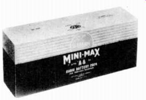
------------- A combination A and B battery for portable receivers. Unit
contains the flat shaped dry cells. Courtesy National Carbon Co.
These can be made in various sizes and shapes depending upon their specific application. Moreover, their weight is quite low, the type shown weighing only 0.43 ounce.
SECONDARY CELLS
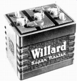
---------------- A lead-acid storage battery with three two volt secondary
cells connected in series is the type commonly employed in automobiles, etc.
Courtesy Willard Storage Battery Co.
In the second major cell classification, the chemical action is "reversible". The active materials can be restored to their original condition by connecting an external voltage source to force current through the cell in the opposite direction. These cells are called "storage" or secondary cells, for, by means of this restoring or charging current, a definite amount of energy is stored in the cell.
Lead-Acid Cells
Shown in Figure 4, the simplest form of lead-acid storage cell consists essentially of positive and negative plates, held apart by a separator and immersed in a liquid electrolyte. The positive plate is lead peroxide, the negative plate is spongy lead, and the electrolyte is a dilute solution of sulfuric acid.
Figure 4A shows the cell employed to deliver current to a lamp. In use, the cell voltage is maintained by chemical action at both plates. Due to these actions, the negative plate accumulates electrons and the positive plate loses electrons. The resulting difference of potential causes the accumulated electrons to flow from the negative plate, through the lamp, and to the positive plate, as indicated by the arrows.
Inside the cell, the chemical action converts part of the electrolyte from sulfuric acid to water, and the plates to a non-useful sub stance called lead sulfate. The action can continue until the plates are completely "sulfated", and the liquid is almost all water. however, a cell is never allowed to discharge this far in good practice since some permanent dam age to the plates occurs.
To return a cell to its original condition, it is connected to a generator as shown in Figure 4B. The generator "charges" the cell by causing electron flow in the direction opposite that described above. As the arrows indicate, the electrons flow from the negative terminal of the generator to the negative plate of the cell, and from the cell positive plate to the positive terminal of the generator.
This charging current produces chemical actions in the cell which are equivalent to electron flow from the negative plate, through the electrolyte, to the positive plate. These chemical actions re convert the plates to lead peroxide and spongy lead, respectively, and return the acid to the electrolyte.
To increase the total available current of a storage cell, a number of individual plates are attached to a lead "strap" to form an integral unit called a "group". The strap also contains a lug or post to which the external circuit connection is made. Then, a group of positive and a group of negative plates are interleaved, with one more plate in the negative than in the positive group. This places each positive plate between two negatives to provide good performance. Also, an insulating separator is inserted on each side of the positive plates, as illustrated in the cut-away view of Figure 5.
Such an assembly of two groups of plates with their separators is called an "element". The complete element is placed in a suitable container, and the electrolyte added to complete the cell.
Regardless of the size or the number of plates, all lead-acid cells develop the same voltage.
While the cell is being charged, the voltage across it rises to about 2 1/4 volts, but three or four minutes after the charging current is stopped, the voltage drops to 2.1.
Then, as the cell delivers current, the voltage drops quickly to 2.0 where it remains until the discharge is almost complete, after which it drops very rapidly. For practical purposes, a cell is discharged completely at 1.8 volts.
To keep it from discharging too far, a lead acid cell should be checked frequently. One convenient method is to take a sample of the electrolyte and measure the amount of acid in it. All liquids are not the same weight, and this fact provides one means ofcom paring them with each other. Be cause of the large quantities existing on the earth, water is used as a standard of comparison, and the ratio of the weight of a liquid relative to that of water is called its SPECIFIC GRAVITY. Technically, the specific gravity of a liquid is the ratio of the weight of a given volume of the liquid to the weight of an equal volume of water. Sulfuric acid has a specific gravity of 1.853, and therefore, for equal volumes, this acid is 1.853 times as heavy as water which has a specific gravity of 1.
Edison Cell
In the secondary cell known as the Edison cell, the active materials are nickel peroxide in the positive plate, and iron in the negative plate. The electrolyte is a solution of potassium hydroxide to which is added a trace of lithium hydroxide.
In both plates, the active material is in finely divided form, and is held in a container which is porous to allow free circulation of the electrolyte.
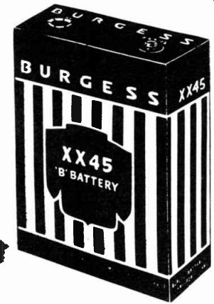
-------------- A dry cell of the form used frequently in battery operated
radios. Courtesy Burgess Battery Co.
Steel tubes containing several hundred holes per square inch are used to hold the potassium hydroxide in the positive plate. In the form of flakes 0.00004 inch thick, metallic nickel is added to the potassium hydroxide to make the plate sufficiently conductive.
Finely perforated steel "pockets" are employed to hold the iron in the negative plate, and the conductivity is increased by the addition of mercury.
The Edison cell provides only 1.2 volts, but it is more rugged than a lead-acid cell, and hence it can stand considerably more abuse. However, these cells are much more bulky for a given current rating. Since the specific gravity of the electrolyte changes very little during discharge, Edi son secondary cells are tested by measuring their voltage which reaches a maximum of 1.8 to 1.9 volts while on charge, and when two readings taken at least 15 minutes apart show no change, the cell is fully charged.
BATTERIES
Most applications require either a larger current, or a higher voltage, than can be furnished by a single cell. When a group of primary or secondary cells constitute the source of electric power in a unit, they are referred to collectively as a battery. Although the term battery means more than one cell, it is common practice also to use the word to designate even a single cell power source.
The various cell connections may be compared with certain combinations of water pumps used to provide the water pressure and flow needed for different purposes.
It is assumed that each water pump runs at a certain specified speed, develops a given pressure in pounds, and can deliver a water flow up to some maximum amount. The maximum water flow is called the "capacity" of the pump, and is expressed in gallons per minute or cubic feet per second.
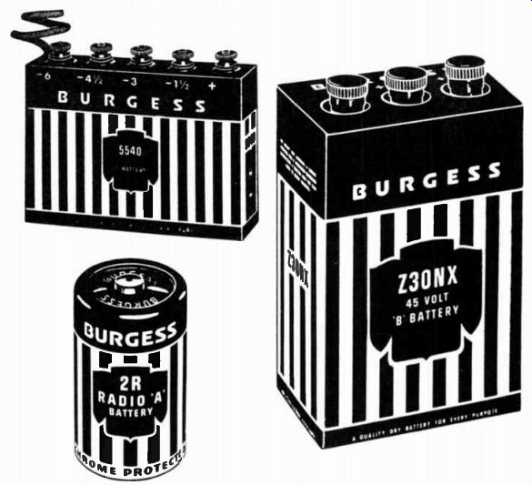
------------ These typical A, B, and C batteries employed in portable
radio and other electron applications all use primary cells.
For this comparison, each cell may be thought of as an electric pump which is capable of supplying a certain maximum current at its rated voltage. Although any amount less than the maximum rated current may be taken from a cell, the electric pressure or emf across its terminals remains essentially constant.
Water Pumps in Parallel
Suppose, for a desired application, a flow of 80 gallons of water per minute is needed at a pressure of 1.5 pounds, and several pumps are available, all the same type, which will develop the required 1.5 lb. pressure but each has a capacity of only 20 gallons per minute.
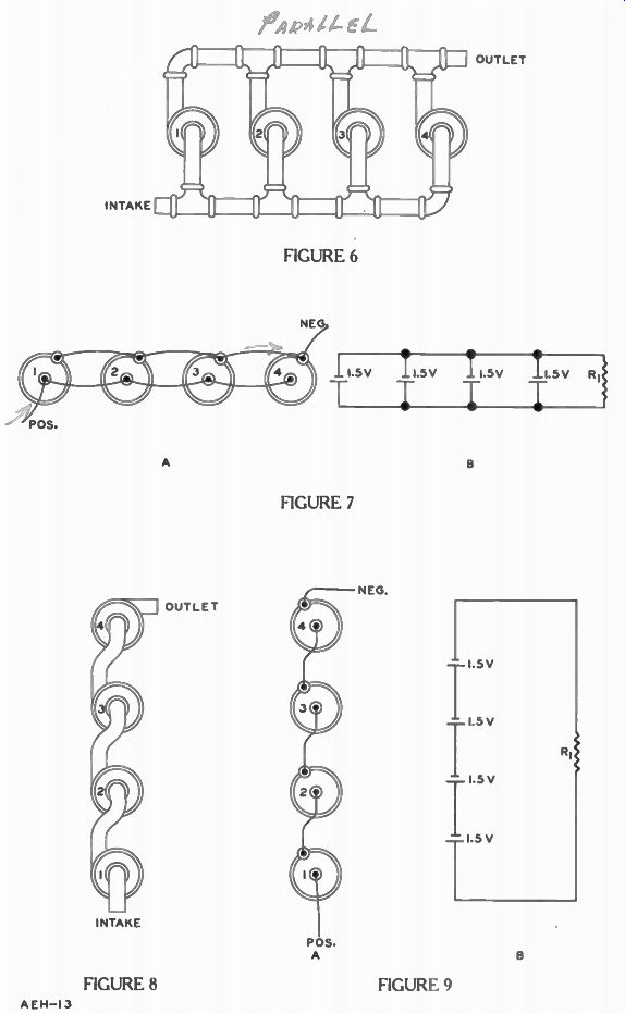
Although one such pump can meet the specified pressure requirement, it can supply only one fourth the total water flow needed at that pressure. Therefore, to obtain the necessary capacity of 80 gal. per min., four of these pumps are connected in the manner shown in Figure 6.
Here, with all intakes connected together, and the four outlets feeding the same pipe, the total pressure developed is still the same as with one pump. This arrangement is known as a parallel method of connection, and the group of pumps may be considered a "battery". The capacity of this battery is equal to four times the capacity of one pump, because each pump takes' 20 gallons per minute from the intake and delivers this amount to the outlet. Thus, the total intake and output of the battery is 20 + 20 + 20 + 20, or 80 gallons per minute.
Therefore, when any number of pumps are connected in parallel to form a battery, the pressure developed by the battery is equal to that of one pump, but the total water current output is equal to the sum of the outputs for the individual pumps.
Electric Cells in Parallel
The same action can be obtained electrically by connecting cells in parallel to form a battery, as shown in Figure 7A. Here, the positive terminal is located at the center of each cell, and the negative terminal at the outer edge or rim. All the positive terminals are connected together to form a single "intake" for the electrons from the external circuit, and all the negative terminals are connected together to provide a single output.
There is a separate path for current through each cell, but with the respective positive and negative terminals connected as shown, the separate currents combine to form the total output current taken from the battery. Also with these connections, the total pressure developed by the battery is the same as the emf of one cell.
As an example, suppose it is desired to take a current of not over .05 ampere from each cell of a battery which must supply a total current of .2 ampere at a pressure of 1.5 volts. For this application, the battery may consist of four common type dry cells connected as in Figure 7A. The battery develops 1.5 volts and with the parallel connection, each cell need supply only .05 ampere to provide the required total battery output of .05 + .05 + .05 -1-.05 =.2 ampere.
WHEN A NUMBER OF ELECTRIC CELLS ARE CONNECTED IN PARALLEL TO FORM A BATTERY, THE VOLTAGE IS EQUAL TO THAT OF ONE CELL, BUT THE TOTAL CURRENT OUTPUT IS EQUAL TO THE SUM OF THE SEPARATE CELL CURRENTS.
Figure 7B is the schematic diagram of the pictorial shown in Figure 7A, but with R1 added.
Using the following form of Ohm's Law we can find the resistance R1: E R=-.
Thus, knowing the voltage is 1.5 volts and the total current to be supplied is .2 ampere, we can substitute in the above to find R1 is: 1.5 .2
Each cell is drained only .05 ampere, while, if only one cell were used with the 7.59 resistor, it would be drained by .2 ampere.
The less current the cell provides, the more closely it approaches its "shelf" life and therefore it lasts much longer.
Water Pumps in Series
Suppose the same four pumps of Figure 6 are to be used in an application which requires a working pressure of 6 pounds, but the needed water flow is not greater than the 20 gal. per min. capacity of one pump. In this case, the four pumps may be connected such that the output of one is fed to the intake of the next as shown in Figure 8. In this arrangement, the pumps are connected in series, and again may be considered a battery.
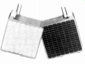
------------ Groups of plates are assembled with a positive plate between
two negatives to form an element. Courtesy Willard Storage Battery Co.
At the outlet of pump No. 1, the water has a pressure of 1.5 pounds, and at this pressure, it enters pump No.2 which increases the pressure by 1.5 pounds to provide a total of 3 pounds for the two pumps. In like manner, pumps 3 and 4 step up the pressure by 1.5 pounds each, so that at the outlet of pump No. 4, the total pressure is equal to 1.5 + 1.5 + 1.5 + 1.5, or 6 pounds. Thus, with the series arrangement, the total pressure supplied by the battery is equal to the sum of the pressures developed by the individual pumps.
Since only pump No. 1 connects to the intake for the battery, and only pump No. 4 connects to the battery outlet, no more water can pass through the battery each minute than can pass through one pump, for unlike the parallel pump battery, in the series battery of Figure 8, there is only one path for water.
Beginning at the intake to pump No. 1, this path is through pumps 1, 2, 3, and 4 in order, to the out let of pump No. 4. Therefore, the capacity of the battery is equal to the capacity of one pump, or 20 gallons per minute.
Electric Cells in Series
Similar conditions exist in an electric battery consisting of a group of cells connected in series.
Figure 9A shows such an arrangement which can be compared with that of Figure 8. In the electric battery, the negative terminal of one cell is connected to the positive terminal of the next, and the remaining positive terminal (of cell No. 1) serves as the positive terminal for the entire battery, while the remaining negative terminal (of cell No. 4) forms the battery negative terminal.
This battery negative terminal corresponds to the outlet of the water pump battery of Figure 8.
Likewise, the positive terminal of the electric battery corresponds to the intake of the water pump battery. Since only cell No. 1 connects to the battery positive terminal, and only cell No. 4 connects to the battery negative terminal, no more current can pass through the battery than can pass through one cell. That is, with the cells in series, there is only one path for current in the battery.
Beginning at the positive terminal of cell No. 1, this path is through cells 1, 2, 3 and 4 in or der, to the negative terminal of cell No. 4. Thus, insofar as the current is concerned, conditions are the same as explained for Figure 8. That is, with only one path for current through the electric battery, the current output of the battery is the same as for one cell.
Assuming ordinary dry cells in Figure 9A, each cell has a difference of potential of 1.5 volts between its terminals. Since the connecting wires represent zero resistance, the positive terminal of cell No. 4 and the negative terminal of cell No. 3 are at the same potential. Now then, the positive terminal of cell 4 is 1.5 volts positive compared with the negative terminal of this cell. And, the positive terminal of cell 3 is 1.5 volts positive compared with its negative terminal, and also corn-pared with the positive terminal of cell 4, due to the connecting wire. Thus, there is a total difference of potential of 1.5+1.5=3 volts between the negative terminal of cell 4 and the positive terminal of cell 3.
Compare the positive terminal of cell 1 with the negative terminal of cell 4, we begin at the latter point and trace through cells 4, 3, 2, and 1 to the positive terminal of cell 1. As we have passed through all four cells, the total difference of potential between the compared terminals is equal to 4 x 1.5 = 6 volts. Each time we passed through a cell, we went from a point of one potential to a point 1.5 volts more positive. Therefore, the positive terminal of cell 1 is 1.5 + 1.5 + 1.5 + 1.5=6 volts positive when compared with the cell 4 negative terminal.
Figure 9B is a schematic dia gram of the pictorial diagram in Figure 9A except that R1 is added.
The advantage of four cells in series over the same four in parallel is that a higher voltage is supplied to Rt . A disadvantage is that each cell must supply the total current, while in a parallel circuit, each cell supplies only a part of the total.
Thus, in Figure 9B with all the cells at 1.5 volts and each cell pro viding .2 ampere, the resistance 11, is found by using the following form of Ohm's Law: ET El = where ET is 4 x 1.5 volts or 6 volts, and I is .2 amperes.
Therefore, substituting these values in the above equation, we find: 6 V 30D.
.2 A
WHEN ELECTRIC CELLS ARE CONNECTED IN SERIES TO FORM A BAT TERY THE VOLTAGE IS EQUAL TO THE SUM OF THE VOLTAGES OF THE SEPARATE CELLS, ALTHOUGH THE CURRENT IS THE SAME AS FOR ONE CELL.
To summarize: for a parallel connected battery of Figure 7, the battery voltage is equal to the voltage of one cell, but the battery current is equal to the sum of the several cell currents. For a series connected battery of Figure 9, the battery voltage is equal to the sum of the cell voltages, while the battery current is equal to the current from one cell.
BATTERY CAPACITY
In the explanations concerning parallel and series connections, the word "capacity" was employed to indicate the rate of water flow in a water pump. Although commonly used in this way with respect to water pumps, ordinarily the term capacity has a different meaning when applied to electric cells and batteries. For the latter application, the CAPACITY RATING of a cell or battery refers to the total quantity of electricity which the device can supply.
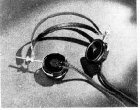
------------ Two headphones, referred to as a headset, equipped with
headband. Use the screws to adjust headset for proper fit. Also note thread
tracer indicating positive leads. Courtesy Brush Development Co.
The unit employed in the capacity rating is the ampere-hour, defined as the quantity of electricity equal to a current of one ampere for a period of one hour. Ampere hours are calculated by multiplying the current in amperes by the time in hours. Thus, when a battery is rated at 100 ampere-hours, it can supply a current of 10 amperes for 10 hours or a current of 1 ampere for 100 hours.
However, while this 100 ampere-hour battery may be able to supply a current of 10 amperes for a period of 10 hours, this does not mean necessarily that it can furnish 100 amperes for 1 hour.
In general, the greater the current the less the capacity, for at a high discharge rate, the electrolyte does not penetrate the active material on the plates rapidly enough, and hence the capacity is reduced.
For example, when discharged at a 6-ampere rate, a 120 ampere hour car battery like the one shown in Figure 5 can operate for 20 hours, and hence it has a capacity of 6 x 20 or 120 ampere hours. But if the discharge current is increased to 150 amperes, the battery will be run down in about 20 minutes (1/3 hour) , and so the capacity is reduced to 150 X 1/3 or 50 ampere-hours.
APPLICATIONS OF INDUCTION
A few lessons back, a door bell was used to illustrate a basic action of electromagnets. Since this same basic action is used in many energy converters to produce motion let's recall some of the important features.
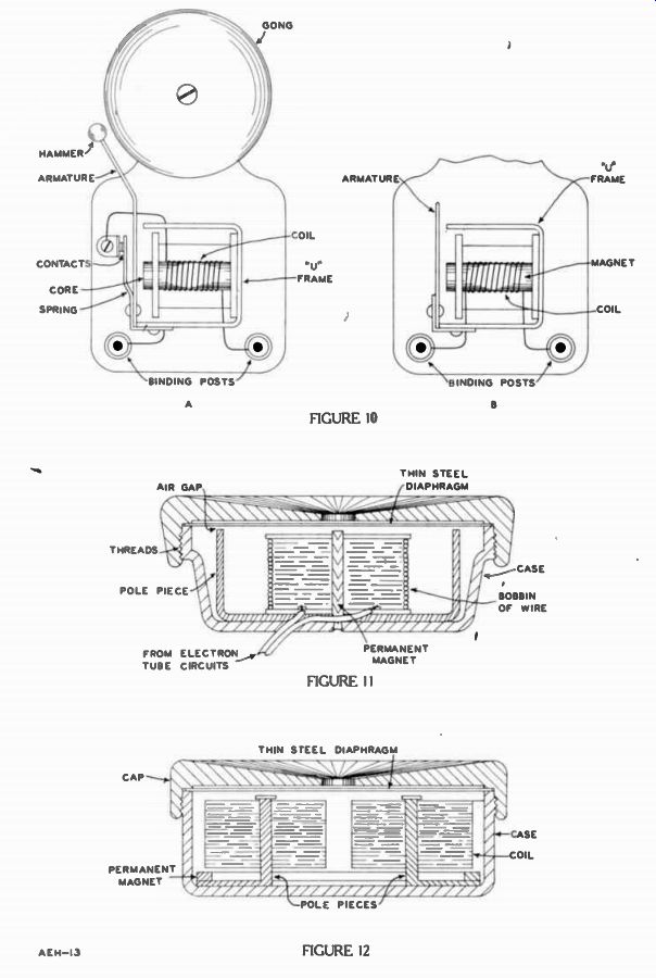
Each of the parts are labeled in Figure 10A. The electromagnet is a coil of wire wound on a cylindrical iron core which is riveted to the center of a "U" shaped iron frame. The armature extends across the open end of the "U" and is held in position by the spring riveted to both the armature and frame.
The upper end of the spring is bent away from the armature, and a stationary contact is mounted in line with a second movable contact, but electrically insulated from it. The spring tension pulls the armature away from the frame to hold the contacts together as shown in Figure 10A. Suppose an alternating current were applied to the electromagnet through the two binding posts.
The current passing through the coil makes the magnetic field of the cylindrical iron bar so strong that it overcomes the spring holding the armature contact closed.
When this happens the contact opens as the armature swings to the right, its hammer striking the gong. As soon as the movable con tact is opened, the circuit is bro ken, the magnetic field collapses, and the spring returns the armature and movable contact to the original position. The instant the contacts touch, the circuit is completed providing you are still pushing the doorbell button. At this instant, electrons flow and the entire action is repeated.
Use of alternating current in most doorbell circuits makes it possible to use a step down transformer from the 117 v.a.c. power line to provide the low voltage needed. However, this is not the only advantage of alternating current. Figure 10B shows a much simpler device called a "buzzer" which works only on alternating currents. Its structure is like Figure 10A except that there is no gong, hammer, or contacts, and the armature is short. Since the armature is short, it moves much more quickly than the long heavy armature and hammer for the bell in Figure 10A. Also, in this particular example the iron core is replaced by a permanent mag net. Although the buzzer operates just as well without the mag net, the magnet model produces the operation we desire.
Now the coil is connected directly to the binding posts and so the current passes through the coil regardless of the armature position. When the switch is closed, one alternation of the current produces a magnetic field in the same direction as the permanent magnet field. This combined at traction overcomes the spring and draws the armature over until it strikes the "U" frame. However, on the next alternation the coil field opposes the magnet. There fore, they cancel out until the spring overcomes the magnetic attraction and snaps the armature back to the position shown.
This action is repeated for successive cycles of the alternating current and the armature striking the "U" frame at such a rapid rate makes the buzzing sound which gives the device its name.
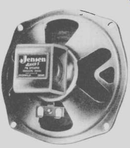
----------- One of the numerous types of PM speakers. Courtesy Jensen
Mfg. Co.
HEADPHONES
Of course, bells and buzzers are not used in very many radio receivers. However, both of them are found in the home and demonstrate the basic action of many energy converters. For example, the headphone used in telephones, hearing aids, and many radios used in communications operates on the same basic principle as the buzzer of Figure 10B. To explain the action, Figure 11 shows a cross-section of one type of headphone mounted inside a protective case ordinarily made of a hard plastic material. A "U" shaped pole piece is fitted into the case. Held in the center of this pole piece, a small magnet is surrounded by a bobbin of wire or coil forming an electromagnet. A screw on cap holds the circular, thin, metal disc called the diaphragm in position just above the magnet and the ends of the pole piece. Since this diaphragm rests on the outer case, there is a small air gap between it and the permanent magnet.
The magnetism of the permanent magnet attracts the diaphragm and holds it under tension: By electromagnetic action, current in the coil sets up a field in addition to that produced by the permanent magnet (PM). Since the polarity of the electro magnetic field depends upon the direction of current through the coil, in one current direction it aids the PM field and in the other direction it opposes this field.
When both fields are aiding, the attraction is increased, the diaphragm is pulled closer. In the other direction, the current produces an opposing field, therefore the magnetic attraction is weakened and the diaphragm moves away.
As a result WHEN ALTERNATING CURRENT PASSES THROUGH THE ELECTROMAGNET, THE DIAPHRAGM VIBRATES AND THE VIBRATION COR RESPONDS WITH THE CURRENT. For high frequency alternating currents the diaphragm moves to and fro rapidly and for low frequency currents the motion is slow.
Sound is a vibration of the air.
As it strikes our eardrums it causes them to vibrate in a like manner and this vibration is carried back to the nervous system by means of small bones. In fact, everything that produces a sound vibrates. It is the vibration of the vocal chords that produce the voice sounds, a vibrating string is used for violin music, and the hammer striking the gong on a bell produces the ringing sound.
These vibrations cause the surrounding air to vibrate and the ear detects these vibrations as the sound.
In the same manner the vibrating diaphragm produces sounds in Figure 11. The higher the frequency of the alternating current the faster the diaphragm vibrates, and the higher the pitch of the sound produced. Also the larger the current, the further the diaphragm vibrates, and the louder is the sound produced. Thus, the sounds heard from the headphone are completely controlled by the amplitude and frequency of the current going through the coil of wire.
Without the aid of the permanent field the diaphragm would normally be released and each alternation of the current would produce a field that would pull the diaphragm in. As a consequence, the diaphragm would be pulled and relaxed twice for each cycle.
Hence, the diaphragm would convert the current frequency into twice the mechanical vibration and this in turn would double the frequency of the sound. Therefore, the sounds would sound high and unnatural.
Connected as an output element in a circuit, the headphone coil carries all the current. If there is a direct current component, the field set up by the direct current must aid that of the permanent magnet. Otherwise this field will reduce or cancel the PM field causing the double frequency sound mentioned above. To assure the proper current direction, one wire of most headphone cords has a colored thread tracer in the insulation to indicate that it should connect to the positive terminal.
The other wire connects to the negative terminal, which usually is ground.
In order to generate the required magnetic field to move the diaphragm, the headphone coil consists of many turns of wire of small diameter. All coils do not have the same d-c resistance; one common type is about 1,000 ohms.
Depending upon the current output for a circuit, different resistances of headphones are required.
For instance, if the d-c resistance of the headphone is too high, the current passing through the coil is too small and hence the sound is weak. On the other hand, if the resistance is too small, then the coil may heat sufficiently to be damaged. In your laboratory projects, the circuits and headphones used are adapted to each other to prevent either of these occurrences.
Not all headphones have the same mechanical structure as Figure 11, some use two coils as shown in Figure 12.
In this case the permanent magnet is a flat "C" shaped ring which is mounted on the bottom of the case. The core and pole pieces are formed as one part and are "L" shaped as seen from this side view. This pole concentrates the magnetic field and passes it through the core of each electromagnet. The electromagnet action is the same as before for each coil.
Both are connected in series and only two leads, one with a color tracer, comes out of the case.
However, in spite of these mechanical variations, the headphone in Figure 12 has the same basic action as Figure 11. Normally the permanent magnet holds the diaphragm under a steady tension. When the current is in one direction through the coils their fields add to the permanent magnet field and the overall at traction is increased. When the current is reversed the field from the electromagnets oppose the permanent magnet. As a result, the attraction is weakened and the diaphragm is relaxed.
Headphones are well suited for giving privacy to the wearer.
However, the amount of sound produced by the headphone is quite limited. This limitation is due to the fact that too much diaphragm vibration causes it to chatter against the pole pieces.
Moreover, if the gap between the diaphragm and pole pieces was increased, the attraction would be weakened and a very large current would be needed then to vibrate the diaphragm. Finally, for such large gaps the sound would be distorted since the attraction would vary appreciably with the diaphragm position as it vibrates to and fro.
LOUDSPEAKERS
To avoid these difficulties where sufficient sound must be produced for a whole room or auditorium, a somewhat different structure is needed called a loudspeaker.
Loudspeakers are used to produce sounds in radios, phonographs, television receivers, at movie theatres and wherever public address or intercom systems are needed.
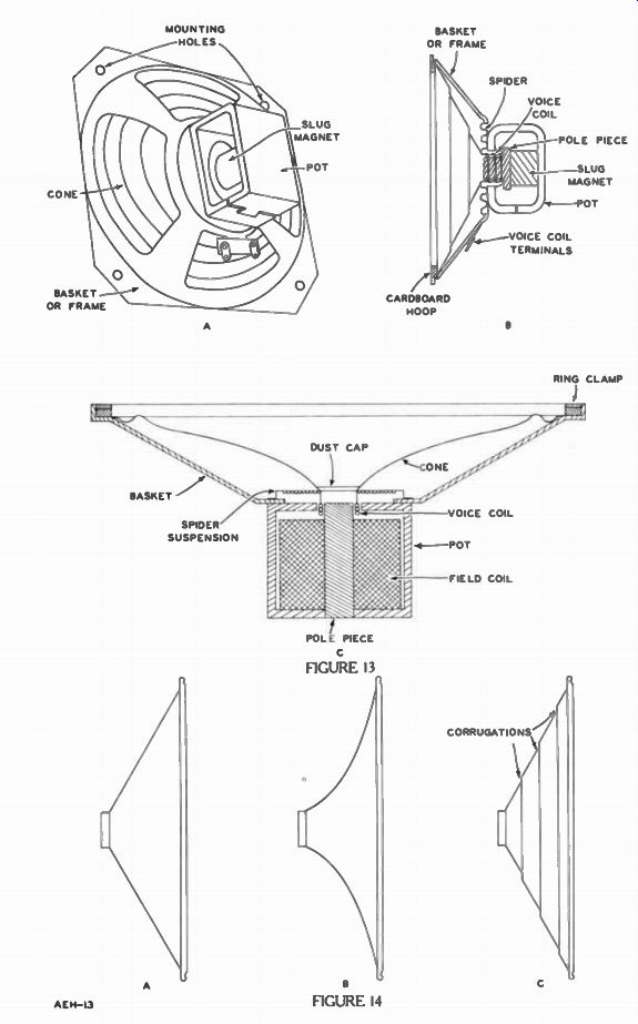
Like the headphones, loudspeakers convert electric energy into mechanical vibration to produce sound. There are a number of types which do this, the differences being determined by the particular application. Figures 13A and 13B are the back and side views of a loudspeaker using a permanent magnet while Figure 13C shows one using a large electromagnet to perform the same function. To identify each, the one in Figure 13A is popularly called a PM speaker while Figure 13C is referred to as an EM speaker.
In general, every PM speaker is constructed about the same. In Figure 13B, the side view shows up almost all of the parts. The magnet is cylindrical in shape with a soft iron wafer in front of it. Both units are friction fitted inside of a large rectangular piece of soft iron labeled the pot. Thus, the magnetic path from the slug magnet is completely enclosed.
Part of the pole piece extends through a hole in the junction of the pot and the frame or basket.
Around this pole piece but not touching either the pole piece, or the pot is a hollow cardboard tube with a coil of wire on it. This is called the voice coil and plays the same role that the bobbin of wire does for the headphone.
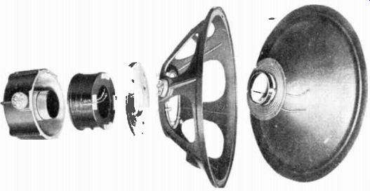
------------- Exploded view of an EM speaker showing its main parts. Courtesy
Jensen Mfg. Co.
Centered by very flexible fiber or thin metal washers called a spider, the voice coil is cemented to the speaker cone. The cone is cemented by its rim to the frame and held tight all around by a cardboard ring. The voice coil terminals are brought out to insulated terminals mounted on the frame. Connecting wires are soldered to these voice coil terminals easily, but it is never done beyond these terminals since this may impair proper speaker operation.
EM speakers in general have the same features. In Figure 13C, this cross-section view illustrates some of the same parts. Ring clamp, cone, basket, spider suspension, voice coil, frame and, pole piece are in about the same location. Instead of a permanent magnet, large numbers of turns are wound about the pole piece and a direct current is passed through the coil to set up a strong magnetic field. For this reason it is called the field coil. Frequently the leads are color coded to indicate the proper connections. In this manner, the high voltage is applied to the outside end of the coil instead of the inside where it might break down the insulation between the coil and loudspeaker frame.
When the current is passing through the voice coil in one direction it produces a magnetic field of opposite polarity to the permanent magnet, and since unlike poles attract the coil is attracted by the magnet. When the current is reversed, the polarity of its field is reversed and so the coil is repelled away from the magnet. The large cone is attached to the coil, and so these coil vibrations produce cone vibrations. Since the cone pushes a large amount of the air back and forth loud sounds are produced.
Moreover, since the coil is free to move quite a distance each way, considerable amounts of sound can be produced without causing a chatter.
Loudspeaker Cone
Practically all speakers radiating sound directly into the air use a cone shaped diaphragm made of paper. These usually are produced by means of a system called felting; in which a mixture of pulp and paper is drawn through a master screen having the desired diaphragm shape. After drying, the cone is removed from this screen. Although in certain applications, it is possible to obtain a greater diaphragm area by making them oval, for most purposes this circular cone is preferred.
Many cones are made of special types of paper. Where maximum efficiency in getting the most sound out is desired, a very rigid paper is best while softer, flexible papers result in high quality reproduction. Sometimes to compromise these two points, corrugations are introduced at the proper intervals on a soft cone.
Three types illustrating some of these features are in Figure 14.
That of Figure 14A has a simple cone shape, while that of Figure 14B is more flared and consequently more rigid. Figure 140 is a flexible, corrugated cone so popular in radio and television PM speakers. Contrary to popular belief just because the cone has a larger diameter it is not better than that having a smaller diameter. The material used, the shape, and the suspension of the cone all play an important role.
Since these cones are very soft, considerable care must be taken in handling them. The fingers or any similar object very easily punctures the cone and these holes may cause inferior sound reproductions or undesired noises.
Cone Suspensions
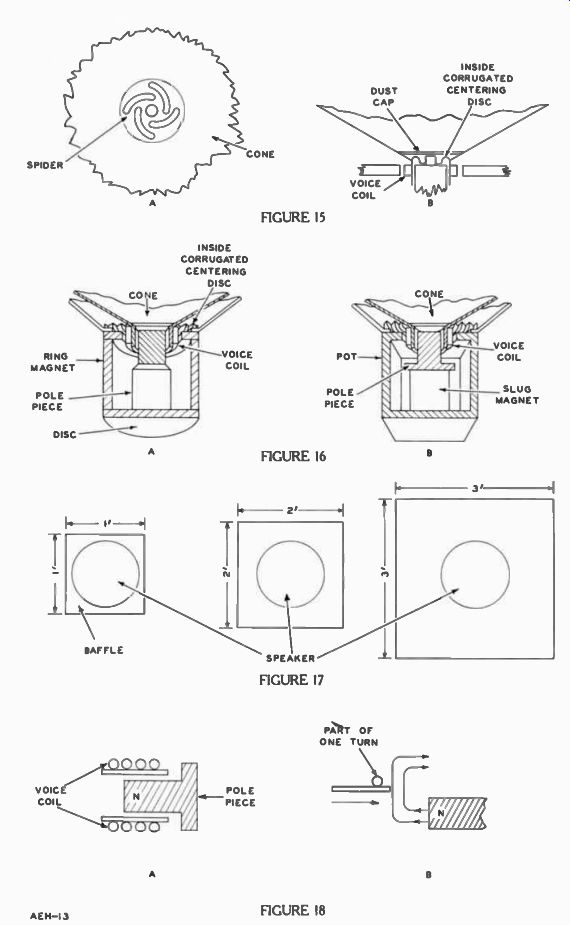
One method of suspending the outer rim speaker cone has been described in Figure 13. Used in these same types of speakers to suspend the cone at its inner edge is the spider or corrugated disc of Figure 15 either of which centers the voice coil properly. Note the cut-outs which look like the legs of a real spider in Figure 15A. The center of the spider has a hole through which a screw is passed to fasten it to the pole piece.
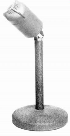
------------- This microphone is mechanically a miniature speaker. Courtesy
Altec-Lansing.
This system, though simple and inexpensive, does not allow the cone to move as freely at all frequencies. Therefore, there is a slightly distorted sound emitted.
Figure 16A shows another type of suspension using a corrugated felted paper on the outside of the cone near the voice coil. This system allows better movement and results in a better sound quality.
Speaker Field Magnets
Speakers employing an EM are sometimes called ELECTRODYNAMIC or DYNAMIC speakers. The strength of its field depends upon the same factors as that of any electromagnet such as the number of turns, the current, the permeability of the core, and so on.
For any electrodynamic speaker, the needed strength of the magnetic field is approximately equal to the power required to be handled by the voice coil. If this power is known, and the d-c resistance of field coil is measured, then the field-coil current and voltage to be applied is calculated from the following equation: E' P=- R For convenience, the above can be rearranged as: PR=E' Suppose the power required is 4 watts and the measured field coil resistance is 2,500n. Substituting in the above equation:
4(2,500) = E2 10,000=E' 100 v=E
Thus, the voltage applied across the field coil must be 100 v. The current through it must be the voltage divided by the resistance: 2,500U -.01 amps.
This power may be obtained from a separate power source or since the coil has inductance as well as resistance, it is often used as part of a power supply pi-filter acting as a filter choke at the same time. When used to smooth out the a-c present from a rectifier, often enough ripple voltage is induced in the voice coil causing it to vibrate at the power frequency and produce a hum. To eliminate this hum, another coil is mounted at the end of the field coil next to the voice coil and connected in series with it. It is arranged so that the hum in it opposes the hum in the voice coil and so it is called a "hum bucking" coil.
In early radios, EM speakers were used almost exclusively since PM were not available to give the same field strength. However, with the new magnets made of aluminum, nickel, and cobalt, called alnico magnets this disadvantage has been largely overcome.
Detailed drawings in Figures 16A and 16B show two popular field structures. In the top view of a speaker in Figure 16A, a large ring shaped magnet provides a strong magnetic field. Its path is closed by the flat disc and center pole piece. Lower strength mag nets as used in ordinary table model radio receivers have slug magnets as in Figure 16B. This is similar to the type shown in the side view of Figure 13B and there are numerous variations depending upon the manufacturer. The pot may be closed as shown, or it may be open. The less expensive have open pots.
In servicing either type of speaker keep in mind the function of each part. Especially, take care not to stretch or deform in any way the speaker cone. When the cone is damaged, the sound is weak and distorted. Small tears may be repaired with speaker cement as it remains pliable when dry; other cements or glues hard en and ruin the cone.
Another trouble common to both types is a badly centered voice coil. Any loud sounds are badly distorted in comparison to low volume sound. Usually it's not advisable to repair these unless you have the same set-up the manufacturer has.
Open voice coils are a rare trouble and just as difficult to repair.
In either case, cheap loudspeakers must be replaced and the expensive models returned to the manufacturer for repairs. He has the necessary equipment to do the job right.
BAFFLES
Speaker performance and hence the sound quality is greatly dependent upon the air that is directly about it. The cone not only pushes away the air mass in front, but pulls the air mass in behind. If the pushed or compressed air in front combines with this thinner or rare-field air in back, they mix and cancel. This effect is quite noticeable at the low audio frequencies.
Sound travels about 1,129 ft. per second in air. Therefore, it takes a very small fraction of a second for sound to go from front to rear of the speaker. The only frequencies at which cancellation is not serious are those high enough that the cone has reversed direction before the sound travels from one side to the other. Then the compressed air from the front aids the air now being pushed by the cone at the back and no cancellation occurs.
Generally, cancellation is reduced by the use of some type of a partition or panel called a battle in which the speaker is mounted to increase the length of the path between the front and back of the cone. Thus with a baffle it takes longer for the sound to reach from front to rear. As a result, much lower frequencies can be produced by the speaker before the cancellation becomes noticeable.
Figure 17 shows how a speaker is mounted in the center of a square baffle. Without a baffle, as when the speaker is removed from its cabinet for servicing or when using the speaker in your lab projects you may note that its full tone has disappeared. Taking a baffle board about 1 foot square, with a hole in the center that the speaker fits over, and mounting the speaker on it restores almost all of the full tone. Actually, the low frequencies cannot cancel out and so more of that sound is heard. Going to a 2 foot square baffle improves the sound more and still lower frequencies are heard. Going to a 3 foot square baffle improves it still further, however, the most noticeable difference probably occurs for the first situation. Radio cabinets perform the same function as a flat baffle. They increase the sound path from front to rear.
MICROPHONES
So far, in this lesson all the applications of the induction principle have dealt with the conversion of electric energy into mechanical motion. Using the principle of induction, a microphone performs the reverse process: converting mechanical motion of sound into electric energy. This meets our earlier definition of an alternating current generator; actuated by a mechanical motion or movement due to sound, a microphone can be said to convert mechanical motion into electric energy, and therefore, it is an a-c generator. Thus, the microphone plays the opposite role to that of a loudspeaker. Since the action that takes place in a microphone is just reverse to a speaker, this makes it possible to use a speaker as a microphone. All of the speakers described in the lesson may be used as microphones though in actual practice only the smaller PM speakers like Figure 13B are so used. These are especially suit able for inter-communications systems in the office, home, or factory.
When sitting in a quiet room you can feel the vibrations produced by your voice if you speak loudly into a book or magazine held close to your face. The same thing happens in a microphone.
The voice produces sound waves which vibrate the microphone cone or diaphragm.
For example in Figure 13B, as the sound moves the cone back and forth the attached coil moves with it. Since it is in the magnetic field of the permanent magnet, the moving coil has a voltage induced in it whose voltage and polarity are determined by the speed and direction of the coil motion.
Figure 18A shows an inset of the voice coil of Figure 13B. This is a side view after a cross-section has been sliced away. Figure 18B shows part of one turn of the voice coil and magnetic field passing out from the pole piece assuming the N pole is at that end.
When the wire moves in the direction of the arrow toward the pole piece, it cuts the magnetic lines. Extending the fingers in the direction of the field and the palm turned so that the wire moves in to it, the thumb points in the direction of the current which is into the paper or away from the reader. When the voice coil moves away from the pole piece, the current reverses. Thus, as the cone vibrates, an alternating voltage is generated at the voice coil.
The headphones of Figures 11 and 12 also can be used as microphones. For example in Figure 11, when the diaphragm is close to the magnet and pole pieces, the reluctance of the magnetic path is low and a large number of flux lines pass through the coil. However, when the diaphragm moves away, a large air gap in the magnetic path increases the reluctance and reduces the flux lines.
As a result, when the diaphragm vibrates, the moving flux lines induce a voltage in the coil.
In any case, the voltage developed by a microphone is very small and there isn't enough power to do much of anything directly with it. For example, the power produced by the microphone might have to be increased 1,000 times in order to drive a loud speaker to its full capacity.
Were it not for the ability of electron tubes to produce this power increase, input devices such as these microphones and loudspeakers would have a very limited value. In fact, the ability of electron tubes to "amplify" or increase signals has been the key to the great expansion and growth of electronics. Paving the way for radio, television, giant brain computers, electronic control, instrumentation, and so many devices too numerous to list, the electron tube still remains the key component to their success. Therefore, just how the electron tube amplifies a signal is important for you to know. This action is described in the next lesson.
IMPORTANT DEFINITIONS
AMPERE HOUR-[AM pier our]-The unit of measure of the capacity of a cell or battery; equal to a current of one ampere for a period of one hour.
BAFFLE-A flat partition used with loudspeakers to improve the quality of the sound by changing its path.
BATTERY-[BAT er i]--A combination of two or more cells connected to have desired voltage and current characteristics. Common usage also applies this term to a single cell used independently in an electric or electron circuit.
CONE-In a loudspeaker the vibrating part causing sound; normally made of soft paper in the shape of a circular cone.
CELL-[sel] -A single chemical unit which converts other energy into electric energy.
DIAPHRAGM-In a headphone, the flat disc caused to move or vibrate due to electromagnetic action.
ELECTRODE-[i LEK trohd]-In electric cells: one of the strips, rods, or plates of metal or other material at which chemical action produces either a surplus or a deficiency of electrons.
FIELD COIL-In an EM speaker, the coil providing the magnetic field produced by a permanent magnet in a PM speaker.
HEADPHONE-[HED fohn]-An electric to sound converter used primarily for individual listening.
LOUDSPEAKER-A device which converts electric energy into sound energy.
MICROPHONE-[MY kro fohn]-A device which converts sound energy into electric energy.
PRIMARY CELL-[PRIGH muh ri sell]-An electric cell in which the chemical action is not reversible, to generate electric energy one or both electrodes are consumed.
SECONDARY CELL-[SEK un dar i sell]-An electric cell in which the chemical action is reversible. After being discharged, it may be recharged by an electric current passed through it in the direction opposite that of the discharging current.
SPIDER-In a loudspeaker, a circular disc centering the voice coil about its magnet.
VOICE COIL-In a microphone or loudspeaker, wound near the magnet the coil of wire which converts either sound or voice vibration into a voltage or a voltage into sound.
WORK DIAGRAMS
When you have completed these work diagrams, check your work with the solutions on the back of the foldout page.
1. Draw the lines necessary to connect the terminals of the four cells so that the cells are in parallel. Indicate the polarity of each cell terminal, and of the battery terminals.
2. Draw lines connecting the four cells in series. As before, indicate cell and battery terminal polarities.
3. Connect the four cells so that the battery thus formed has terminal voltage and current capacity equal to twice that of a single cell.
Indicate terminal polarities.
4. Connect the terminals of the four cells to form a battery such that one terminal is + 4.5 volts and another is -1.5 volts with respect to a third terminal employed as a reference point. Indicate the potentials of the three battery terminals.
---------------
---------------
---------------
---------------
--------------
FROM OUR Director's NOTEBOOK
OBSERVING THESE RULES WILL HELP A WORKING DAY
Never show your temper. Indulge in no sarcasms. Permit other people to have views. Never contradict an irritated person.
Keep unpleasant opinions to yourself. Be considerate of the rights and feelings of others. Always use pleasant words.
Take time to be polite. Never order people about.
Be gracious and accommodating. Always grant a reasonable favor. Don't try to fool your caller, he may be a smart man, and make sure your way is best before insisting upon it
Yours for success, DIRECTOR