AMAZON multi-meters discounts AMAZON oscilloscope discounts
Lesson AEH-16E3
ELECTRONS PILOT AIRCRAFT
Once the desired altitude is obtained and the course established, the air line pilot flips a switch and then relaxes while an electronic pilot flies the plane. Flying conditions change from time to time, but the predetermined altitude, speed, and direction are maintained by the equipment which automatically compensates for the changing conditions.
So dependable is this operation, engineers seriously predict that, in the near future, once an airplane is "checked out" on the run way, pressing a button in the control tower will cause the plane to automatically take off, assume course, and land at the chosen destination.
This is only one example of the many robot controls possible with electronics.
Familiar examples in the home are the automatic pop-up toaster and the washing ma chine which, unattended, washes, rinses, and dry’s clothing.
Fundamentals
AMPLIFIERS
Contents
Grid Bias Methods Separate Supply Cathode Bias Grid Leak Bias Negative Leg Bias Types of Coupling Resistance Coupling Impedance Coupling Transformer Coupling Amplifiers in a Radio
On some street cars there is the sign, "pay as you enter". It mould be a good thing if that sign were pasted over every career in life. For you get only what you pay for, and pay for in advance.
In any calling of life, the money, or study, or pains, or whatever it is, must first be paid before the rewards come.
-Dr. Frank Crane
AMPLIFIERS
One important reason for the enormous growth of electronics is the almost unlimited speed at which the tubes and circuits can operate. For example, the small spot of light which illuminates the screen of a 21 inch television receiver travels at an average speed of nearly 13,000 miles per hour. But that is not all. During its movements across the screen, to reproduce the light and dark areas of the picture, the light intensity of the spot may vary as often as four million times per second.
In the form of electric energy, these variations are expressed as a-c frequencies in terms of cycles per second. When converted to sound energy, frequencies from about 15 cycles to 20,000 cycles affect human ears, and therefore, can be heard. These are called audio frequencies. There are no exact or definite limits to the range of audio frequencies, be cause the response of human hearing varies considerably for different individuals.
Designed only for speech, the telephone systems operate on frequencies from 300 to 3,000 cycles per second. To reproduce both speech and music, many sound recordings and radio broadcast pro grams include frequencies from about 50 to 5,000 cycles per second. Although 14,000 cycles per second often is regarded as the upper audio frequency limit for the average listener, much higher frequencies are necessary for high fidelity reproduction.
Just as important, but not so well known, in industry there are many changes of temperature, pressure, weight, movement, and speed which occur at these low audio frequencies. By means of energy converters similar to the headphone and loudspeakers described in a previous lesson, these changes are converted to corresponding electric voltages or currents.
All of these changes provide desirable applications for automatic electronic control but, in practically every case, the original electric frequencies produced are so small that they must be amplified sufficiently to operate even a meter much less relays, motors, or other mechanisms.
Modern radio and electron applications are based on the important fact that very weak signals can be built into strong ones. A majority of the tubes used in electronics do just this. Although some amplifiers amplify substantially a single frequency or a narrow range of frequencies, for many applications the amplifier is designed to operate efficiently over a range of frequencies. For example, all of the audio signals generated in a microphone must be amplified until they can operate loud speakers, recording devices, radio or television transmitters.
In the previous lessons on triodes, tetrodes, and pentodes, we described how an electron tube amplifies voltage changes or signals applied to the grid. At the same time we pointed out the need for a d-c voltage or bias on the grid so that the tube operated properly about midway between cutoff and saturation. We also showed a radio receiver where the signal is amplified by one tube and then passed on to the next.
However, we did not stop and explain to you how the d-c voltage needed to bias each tube was produced nor what was necessary to pass the signal from the plate circuit of one tube to the grid of the next. Since both of these are important in practical amplifier circuits, we will stop and consider these needs now.
GRID BIAS METHODS
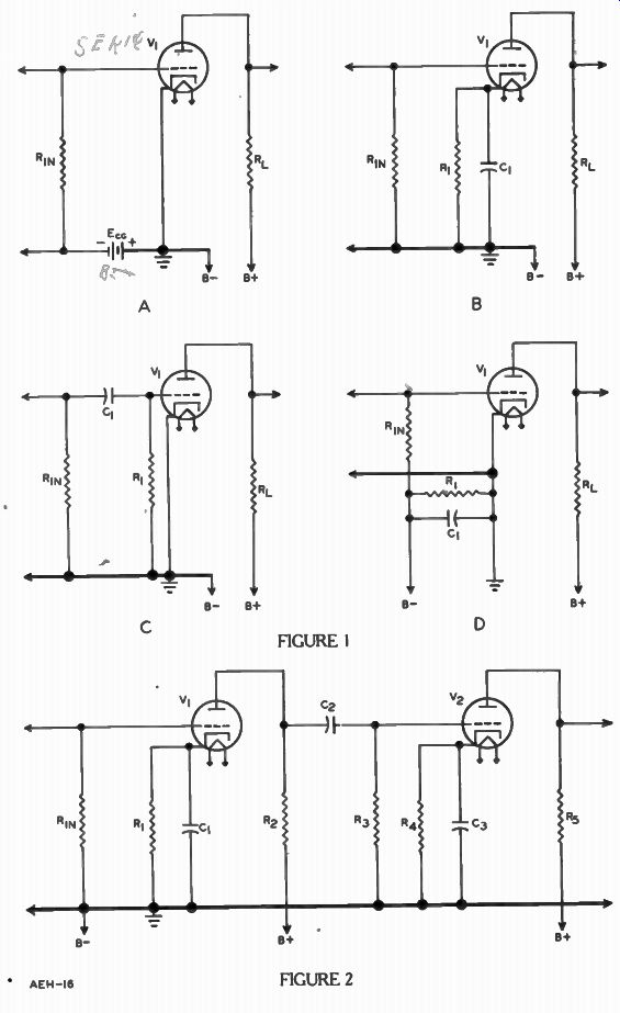
Since the GRID BIAS determines the operating point of a tube, it is very important that whatever method is used maintains this negative voltage at the desired voltage in order to have proper operation. At the same time, the method must be simple to be practical. Four methods are shown in Figure 1. Although each method differs from the others in certain details, basically they all develop and apply a fixed negative voltage on the grid with respect to the cathode.
Separate Supply
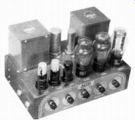
------------ An amplifier is used in practically every electronic application.
This particular unit is capable of supplying sound from a microphone, radio,
or phonograph to o large audience. Courtesy Altec Lansing Corp.
Where a highly stable grid voltage is essential, a separate battery can be used as shown in Figure 1A. When used for this purpose it is called the C battery.
Normally, it is made up of a number of 1.5 volt dry cells connected in series to deliver the required voltage. Some batteries have a number of terminals making avail able several different voltages from 4 1/2 to 22 1/2 volts, or more.
By connecting the positive terminal to ground as shown in Figure 1A, and connecting the bottom of the grid resistor R,,, to a selected negative terminal the required bias is applied to the grid.
In most operations, the grid of the tube draws little or no current. Therefore in these applications a "C" battery in a bias circuit like that of Figure 1A, lasts as long as its "shelf life". Also, since little or no current is drawn from the battery, the cells are very small. This makes for a compact battery.
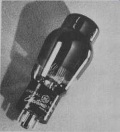
------------- Tubes designed for power amplifier applications are usually
larger than other amplifier tubes to make them more capable of dissipating
the heat generated. Courtesy General Electric Co.
For some large electronic equipment such as a broadcast transmitter, the grid is driven positive by the alternating voltage, and the grid draws an appreciable current. This grid current would soon run the battery down. Therefore, a separate power supply or small d-c generator is used sometimes in place of the battery to supply this fixed bias voltage. The positive terminal of the "C" supply connects to the cathode and the negative terminal to the grid resistor.
When a battery or other independent source of d-c is connected in the position of E,, Figure 1A, it is called a fixed bias. It is used in amplifiers where the required operating bias is near or beyond plate current cutoff.
Cathode Bias
To eliminate the independent voltage source in the grid circuit, many amplifiers employ the self bias method shown in Figure IB. With . .no signal at the input to the amplifier stage, the tube is said to be in its "static" condition.
That is, the plate current remains at a steady or d-c value. The path of the plate current is from the negative terminal of the "B" supply (B-), up through the cathode resistor R1 , from the cathode to the plate within the tube, and then through the plate load Et' , back to the positive terminal of the plate supply (B + ) . Since the electrons flow from the ground to the cathode end of the resistor, the voltage across R1 is positive at the cathode with respect to the ground end. Then with the grid of the tube connected to ground through the grid resistor Rin, the grid is at a point negative with respect to cathode.
That is, the cathode is positive with respect to ground and the grid. Thus, the voltage developed across resistor R, in the cathode circuit serves to bias the tube grid: When an alternating voltage is applied to the tube grid, the plate current fluctuates. Since the plate current determines the voltage across cathode resistor R1 , the grid bias varies with this current.
Generally, this unsteady grid voltage is undesirable, and so it is necessary to connect capacitor C1 across R1 to eliminate the variation.
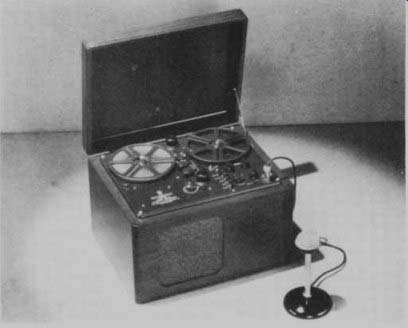
----------- This tape recorder incorporates an amplifier to build up the
signals from a microphone or radio until large enough to operate the "recording
head". Courtesy Brush Development Co.
With a steady current, C1 charges to the fixed voltage across R,. When the current decreases, C, has to discharge through R1 before the voltage can decrease, but not enough electrons discharge through R, to permit an appreciable change in voltage before the current increases again.
Thus, the charge and discharge action of the capacitor tends to maintain a constant voltage across R, in spite of plate current changes. It has the effect of passing the alternating portion of the plate current around the resistor and for this reason it often is called a cathode bypass capacitor.
The cathode bias method avoids the bulk and expense of a separate "C" supply. However, it is not good for circuits that must be operated at cut-off. A large grid voltage is required to cut the tube off but when the tube is cutoff no plate current exists to produce the bias.
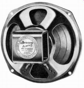
------------ Amplifiers are used in radios to build up the signal until
enough power is available to operate a loudspeaker like the one pictured here.
Courtesy Jensen Mfg. Co.
Grid Leak Bias - Another method of self bias employs a resistor and capacitor combination in the grid circuit of the stage as shown in Figure 1C, using R, and C1 . When the a-c input signal is in the positive half of its cycle, the grid, acting as a diode plate, draws a small current which charges capacitor C1 to a negative polarity at the grid end. During the negative half of the a-c input signal cycle, since electrons cannot flow from the grid to cathode the capacitor discharges from its negative terminal through resistors R, and Rin back to its positive terminal. The direction of this discharge current is such that the grid end of resistor 11, remains negative with respect to the other end which connects to the ground and cathode.
In order to maintain a fairly constant voltage drop for biasing, the capacitance of C, is so chosen that it will charge quickly with the grid current, and a high resistance is selected for R1 so that the C1 charge thus leaks off slowly. This method is called grid leak bias.
Grid leak bias is seldom found in amplifiers operated midway between cut-off bias and saturation.
These are circuits where the signal in the plate circuit should be just like the one on the grid except amplified. Since grid leak bias depends on the grid swinging positive on the a-c peaks to charge C1 , it operates only in circuits where the signal is changed or distorted.
Negative Leg
Bias A form of self and fixed bias, called negative leg bias, is shown in Figure 1D. In this circuit, the path of the total plate current of several or all other tubes is from the negative terminal of the plate supply (B-) through R1 to ground. This develops a voltage across R, with a polarity which is positive at the ground end and negative at the other end where the grid resistor R,„ is connected.
This places a negative potential on the grid with respect to the cathode, thereby biasing the tube.
As in the other self-bias methods, capacitor C, prevents a-c voltage changes from appearing across the bias resistor R1. Practically all of the electronic equipment uses one of these four types of bias. Although the method used in Figure 1A can be used in practically every circuit, it is expensive. The method that costs the least and still does the job is preferred and in describing various circuits in this program, we shall point out the bias method and why it is used.
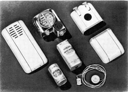
-------------- Enclosed in the metal case just above the "B" battery
is the small amplifier required to build up the signal picked up by the microphone
behind the grill work until it is sufficient to operate the earphone in the
lower right corner. Courtesy Paravox, Inc.
TYPES OF COUPLING
In an earlier lesson, electron tubes were described as being able to produce a large variation of voltage in the plate circuit for a small variation in grid voltage.
This process is called amplification and the circuits used for this purpose are referred to as amplifier circuits or amplifiers. Their output voltage may be further amplified by impressing it upon the grid circuit of another tube.
Each tube and its associated circuits are known as a stage, and when a SIGNAL passes from one stage to the next in sequence, such an arrangement is called cascaded stages. For instance, V1 and V2 of Figure 2, 3 or 4 are cascaded stages.
The passing of the signal from one amplifier stage to another is called coupling. For cascade operation coupling is quite important.
Three basic methods used in amplifiers are:
1. Resistance coupling
2.. Impedance coupling
3. Transformer coupling
Resistance Coupling
Figure 2 shows a coupling arrangement consisting of resistors R2 and R3 and capacitor C2. Usually this arrangement is called a resistance coupled amplifier, al though some call it RESISTIVE-CAPACITIVE COUPLING. The circuits of tube 1 / 1 are the same as explained for Figure 1B except that the plate load resistor is labeled R2 instead of RL. The grid and cathode circuits of V. are the same as those at V,.
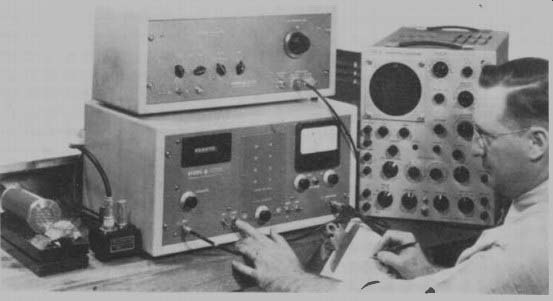
------------- Amplifiers are important in these nuclear laboratory instruments
used to measure the radioactivity of a sample in front of the counter tube
in lower left corner. From DTI Labs.
Capacitor Co connects between the plate of V1 and the grid of V2 and has two distinct functions.
One is to block the positive d-c plate voltage of tube V, from the grid of tube Vo. The other function is to transfer or pass the amplified a-c signal from the plate of V1 to the grid of V2.
When the circuit is in operation but with no input signal voltage, electrons flow from B- through R,, through V, from cathode to plate, and back to B+ through Ro. Also, there is a path from B - through R3, to C.>. There is no continuous current in this path but electrons will flow from B - through R3 only until Co is charged. While C2 is charging, electrons will leave it and flow along with the V, plate current through R2 to B +. Under these conditions, C2 is charged to the plate supply voltage minus the voltage across the plate load resistor R2. When capacitor Co is fully charged, there is no current through or voltage across R3, the grid resistor of tube V2. At this same time, capacitor C1 charges to the voltage across RI. Suppose now, a positive alter nation of signal voltage across
It in drives the grid of V, less negative and thereby causes an increase of plate current. According to Ohm's Law, the increase of current causes an increase of voltage across R1 and Ro. however, as explained for Figure 1, the action of capacitor C, tends to prevent a change of voltage across R1 , but the increased voltage across Ro reduces the plate voltage and also the voltage across C2 and R3 in series.
With reduced voltage across it, C2 starts to discharge and the path of the discharge current is down through R: , to B-, and through R1 , and V, back to C2.
This discharge current causes a voltage across which makes the grid of V2 more negative with respect to its cathode.
When the input signal voltage reduces or reverses polarity on the negative alternation so that the grid of V, becomes more negative with respect to the cathode, the plate current is reduced. With less plate current the voltages across R1 and R9 are reduced.
Again, the action of C1 tends to maintain a constant voltage across R1 but the reduction of voltage across R allows an increase of voltage across C2.
With an increase of applied voltage, capacitor C2 charges and, as explained previously, the path of the charging current is from B - through R3 to one plate of C2 and from the other plate through Ro to B +. The voltage across R3, caused by the charging current, makes the grid of V2 more positive with respect to its cathode.
Thus, by causing capacitor C2 to charge and discharge, the a-c component of the plate current in V, produces an a-c voltage across and the grid-cathode circuit of V2. For good results, the resistance of the plate resistor R2 should be fairly high and capacitor C2 must have sufficient dielectric strength to prevent a break down which would allow d-c plate voltage from V1 to leak through to the grid of V2.
Changes in frequency have practically no effect on the voltage across a resistor, therefore, the FREQUENCY RESPONSE of resistance coupled amplifiers is fairly uniform over a frequency range which makes for good quality sound reproduction. With the efficient performance of modern amplifying tubes, it is possible to achieve economical operation at relatively low plate voltage, and therefore, the voltage drop in the plate load resistor is not a serious disadvantage. The coupling units consisting of resistors and capacitors are compact, light in weight, and relatively inexpensive. Hence resistance coupling makes for a good, economical amplifier.
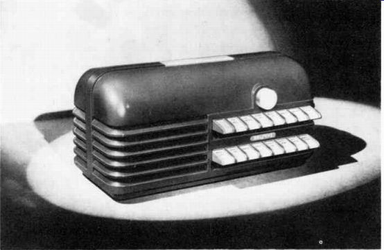
------------ Amplifiers are used in office inter-communication systems.
Courtesy Bell Sound Systems, Inc.
Impedance Coupling
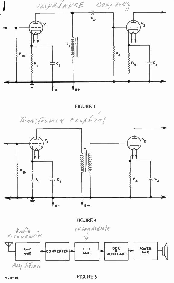
In the circuit of Figure 3, inductor L1 replaces resistor R2 of Figure 2 and, with coupling capacitor C2 and grid resistor R3, it forms what is known as an impedance coupled amplifier. The inductor is made of a number of turns of wire wound on a form.
Some have an iron core as indicated in Figure 3. Due to its self inductance, the coil presents a high opposition to the frequency variations of the plate current but has a low resistance to direct current.
In general, the action of impedance coupling is much like that of resistance coupling but the lower d-c resistance of the inductor causes a smaller loss of power supply energy. However, since the self-inductance of inductor L1 varies with frequency, for equal input signal voltages, the voltage developed across it varies with changing frequency. There fore, the response of the impedance coupling circuit is not uniform over the same range as for resistance coupled amplifiers. An other disadvantage of this coupling method is that an inductor with a large number of turns and a laminated core, is heavy and relatively expensive.
Transformer Coupling
Figure 4 shows a transformer coupled amplifier arrangement using an iron core transformer T1 . The transformer primary is in series with the plate circuit of tube V, while the secondary is in the grid circuit of tube V.. Changes in primary current in duce a corresponding voltage in the secondary. In addition to the amplifying action of the tubes, the transformer can be made to step up the signal voltage nearly directly proportional to the turns ratio of the windings. However, there is a limit to the number of times a transformer can step up the signal voltage.
Practical considerations normally keep the step-up ratio relatively low. For proper operation, the primary must present sufficient inductance at low audio frequencies, and therefore must be wound with a comparatively large number of turns.
To obtain a step-up ratio, the secondary winding must have more turns than the primary, but as turns are added, the "distributed capacitance" between the adjacent turns and the various layers increases. That is, due to the closeness of adjacent turns, they act as plates of small capacitors and the more turns, the greater the number of small capacitors.
These capacitors tend to short the signal across the secondary as the frequency increases. Such shorting action is undesirable because it prevents the signal from reaching the grid of tube V. at the maximum voltage. Thus, the number of primary turns must be sufficient to provide proper opposition due to self-inductance at low frequencies, while the number of secondary turns must be limited to keep the shunting effect of the capacitors low at the higher frequencies. To satisfy both requirements, the transformer turns ratio seldom exceeds 3 to 1.
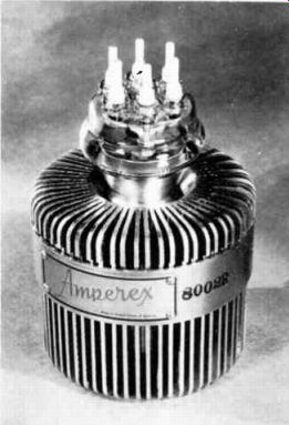
------------- Tubes designed to deliver very powerful signals must use
fins like these or a water cooling system to keep from overheating. Courtesy
Amperex Electronic Corp.
Since transformers are more expensive than resistance coupling, they are not used unless some special circuit requirement can be better met by the transformer. For example, an electron tube produces a large voltage change and a moderate current but a loudspeaker requires a large current and small voltage. Here is where the transformer coupling is very useful. As explained in a previous lesson by using fewer turns in the secondary it has a larger current and smaller voltage than the primary.
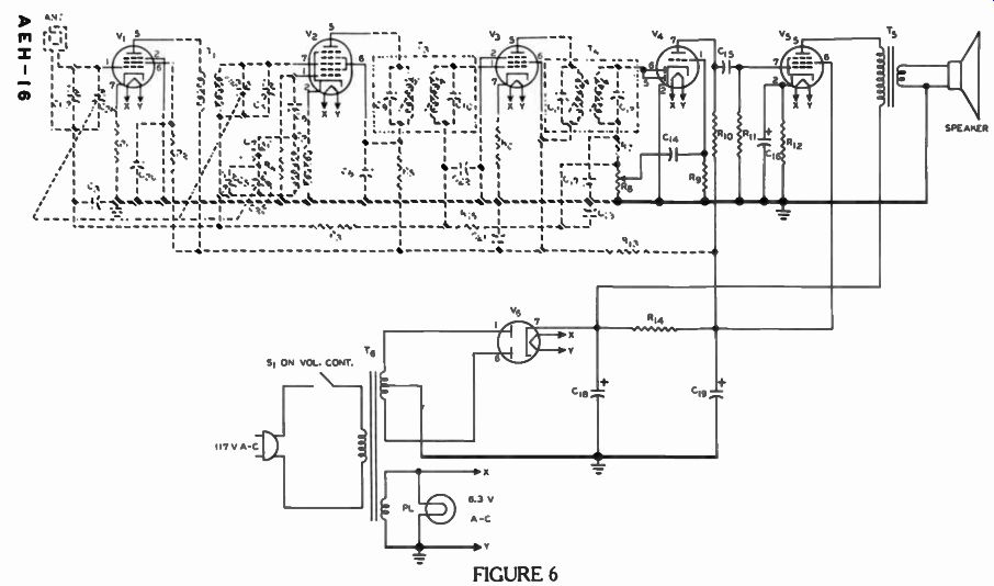
PRACTICALLY ALL LOUDSPEAKERS ARE COUPLED TO THE LAST TUBE IN THE AMPLIFIER BY MEANS OF THE TRANSFORMER. AMPLIFIERS IN A RADIO
Figure 6 is the schematic diagram of the radio receiver introduced in an earlier lesson.
Signals from the broadcast station are intercepted by the antenna and passed from stage to stage until it reaches the loudspeaker.
Among other things each tube that it passes through amplifies the signal.
The path that the signal takes is illustrated by the block diagram in Figure 5. Since the power sup ply does not handle this signal, it has been omitted. The three cornered symbol represents the antenna. The signals broadcast by the radio stations are intercepted by it and fed to the "RF-AMP". Every broadcast station is as signed a particular frequency to radiate its program on. Since high frequencies are required to radiate for an appreciable distance, all frequencies above the audio range are often referred to as radio frequencies (r-f) and any amplifier designed to amplify these frequencies is called an r-f amplifier.
Since it would not be desirable to receive signals from all stations at the same time, the one desired is selected in the "RF AMP." When you adjust the tuning knob on a receiver it rotates a variable capacitor that determines which station's frequency is tuned in.
Since we are now considering amplification, how this selection is accomplished is described in an other lesson.
This selected frequency is fed into the converter stage. Here, the broadcast station frequency is changed or converted into a lower frequency within the radio. This is done because the radio amplifies this second frequency better than the one from the broadcast station. The converted frequency is referred to as an intermediate frequency and is amplified by the intermediate frequency amplifier, abbreviated IF AMP. In the fourth stage, this amplified intermediate frequency signal is "detected" by a rectifier and amplified. Due to the formation of the signal broadcast, the rectified signal is the same as that produced by the sound at the broadcast studio. These are called audio frequencies, and they are amplified by the audio amplifier, AUDIO AMP. Finally, these amplified audio frequencies are again amplified by a power amplifier, POWER AMP, which drives the loud speaker.
Certainly, the electron tube is a magic device, taking sounds in a room miles away and putting them into your living room. And this is not all, in television both the sound and the scene are transferred into your living room by a very similar process.
Referring again to Figure 6, among other things each of the tubes, except rectifier V6, amplifies the signal before passing it on to the next stage.
------------- Car radios have a circuit similar to Figure 6. Courtesy
Motorola, Inc.
V1 uses cathode bias produced by resistor R1 in the cathode circuit. However, there is no cathode bypass capacitor. Since the signal is very small at this point, R1 doesn't have to be large to produce sufficient bias to keep the grid from going positive during the positive peaks of the signal.
As a result very little undesirable effect is produced by leaving the capacitor off. In fact, as you will find out in a later lesson and your laboratory projects it often improves the operation of high frequency stages. T, is the trans former coupling between V1 and V2. Few turns and no core are needed in the transformer at radio frequencies, therefore, it is a compact, economical coupling method.
Vo uses grid leak bias developed by C6 and R3,. Again the signal is coupled by a transformer, T3, to the grid of V3. Like V1 , V3 uses cathode bias developed across R6 and without a cathode bypass capacitor. Transformer T4 couples the output of Vs to a rectifier circuit called the detector which uses plates numbered 5 and 6 and the cathode of V,. The fluctuating voltage across potentiometer It, is developed by this rectifier.
Depending on the position of the sliding contact on R8, more or less of this voltage is coupled by C14 to the grid of the triode in V,. Therefore Rs is the volume control, and the lower part of R8, C14 , and It, provide resistance coupling for the signal.
Although V1 , V2 and V: , have other functions besides amplifying the signals, the triode section of V, and the beam power tetrode V, are just amplifiers.
Triode V4 in Figure 6 uses a unique bias method, called CONTACT BIAS. Due to its closely spaced grid wires, a number of electrons going from cathode to the plate strike the grid and thus make it negative. If R8 is a very high resistance these electrons leak off slowly, and therefore the grid remains sufficiently negative to keep the signal from making the grid positive.
Since the bias voltage is developed by the electrons coming in contact with grid wires this method is called CONTACT BIAS. Although all tubes develop this effect, usually it is far too small to use. Only with high mu tubes and small signal voltages is it useful.
Plate load resistor R10, capacitor Cir„ and grid load resistor R11 resistance couple the amplified output of V4 to the grid of V5.
V5 is cathode biased by R12 which is bypassed by C49 to prevent un desirable fluctuations in the bias.
Notice that the plate of V5 is connected through the primary winding of T, directly to the rectifier output while the screen grid is connected to the output of the pi filter consisting of C18, R14, and C18. T5 couples the amplified signal for V5 plate to the loud speaker.
In this lesson only amplifier circuits were described. There is a multitude of electronic applications where these amplifier circuits are used, but these are not the only uses for electron tubes.
From what we have said about the operation of the radio receiver in Figure 6, you know that these tubes can perform several other major operations. What some of these circuits are and how they are applied to this radio receiver are described in the next lesson.
IMPORTANT DEFINITIONS
AMPLIFIER-[AM pli figh er]-A circuit designed and used to increase the. _current, voltage, or power of the signal.
"C" BATTERY-A low voltage-low current battery used as a source of fixed voltage for grid bias.
CASCADE STAGES-[kas KAYD STAY j's]-A number of stages so connected that the output of one impresses the signal on the input of the next.
CATHODE BIAS-A bias voltage obtained by tube current through a resistor in the cathode circuit, making the cathode positive in respect to grid.
CATHODE BYPASS CAPACITOR--A capacitor connected across the cathode resistor to maintain a steady voltage drop across this resistor.
CONTACT BIAS-The bias developed across a high resistance grid load resistor due to a current caused by electrons bombarding the grid.
COUPLING-[KUHP ling]--The association between two related circuits that permits the transference of energy from one to the other.
FIXED BIAS-A bias voltage obtained from a battery, power supply or generator, which is fixed in value and not determined by tube current.
GRID LEAK BIAS-A bias voltage developed across a resistor capacitor combination in the grid circuit of an electron tube by grid current flow.
IMPEDANCE COUPLED AMPLIFIER--A type of low frequency amplifier in which an inductor forms the plate load of one stage, and the signal is transferred from the plate of one tube to the grid of the next by means of a capacitor.
NEGATIVE LEG BIAS-A bias voltage developed across a resistor in the negative leg of the "B" supply by total tube or circuit current.
RESISTANCE COUPLED AMPLIFIER--A type of low frequency amplifier in which a resistor forms the plate load of one stage, and the signal is transferred from the plate of one to the grid of the next stage by means of a capacitor. Sometimes it is referred to as a resistance-capacitance coupled amplifier.
STAGE-All of the components of a circuit containing one or more tubes with one input and a single output.
TRANSFORMER COUPLED AMPLIFIER-An amplifier in which the signal in the plate circuit of one stage is coupled to the grid of the next by means of a transformer.
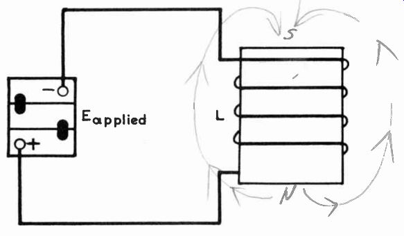
WORK DIAGRAM
(a) With arrowed lines, indicate the direction of magnetic flux lines around the coil, and mark the magnetic poles.
-----------
----------
----------
---------