AMAZON multi-meters discounts AMAZON oscilloscope discounts
ELECTRONS SOLVE PROBLEMS
In the course of a military action, an artillery battery is to lay down a barrage immediately at a point many miles from its position. Reference to a set of charts permits the proper trajectory to be determined quickly, and in a few minutes the shells are landing on the target. Calculation of a trajectory consists of an involved and time consuming series of mathematical computations, to simplify which, the set of charts has been worked out with the aid of an electronic calculating machine.
Much of the success in modern research and development depends on results obtained from elaborate mathematical computations. An expert mathematician could not complete some of these problems in a life time yet an electronic calculator or "brain" can solve them in two or three weeks. Applications in business include calculation of insurance premiums, and machines which keep books, bill the customer, record payments, or maintain perpetual inventory.
Fundamentals
METER CIRCUITS
Contents
Measuring the Magnetic Effect D'Arsonval Meter Electrodynamometer Type Meter Ammeters Ammeter Sensitivity Ammeter Shunts Shunt Calculations Voltmeters Voltmeter Multipliers Voltmeter Sensitivity Multiplier Calculations Meter Error Calibrating Meters Ohmmeters A Complete Multimeter Vacuum Tube Voltmeter Reading the Scales Zero Procedure Power Supply . Balance Amplifier Input Circuits D-C Input A-C Input Ohms Input
VTVM Rating
If the control of one's self is the greatest of goals, the control of one's thoughts is still greater, for what a man thinketh, so he is.
-Dr. Frank Crane
METER CIRCUITS
Electric meters are the eyes through which the radio, television, or other electronic technicians see their circuits. How true this is becomes apparent when you compare the mechanic's job to an electronic technician's. The mechanic can watch the machine in action. He can see what is stuck, broken, or slips. On the other hand, look into the chassis of a radio receiver which shows most of its parts. Other than a warm tube there is no activity to see.
Only with a meter can the technician "see" what voltage, current, or resistance is wrong.
To be a good pilot, you must know how an airplane flies. It isn't enough to know which controls do which, you must know how each one does its duty. The same holds true with meters. Although you can use one by knowing which knobs to adjust and how to read the scale, the real competent use of the meter comes in knowing what is inside. With this knowledge you can know the advantages and disadvantages of the meter, or its use in a particular circuit. Therefore, this lesson describes how a meter operates.
MEASURING THE MAGNETIC EFFECT
By a simple experiment, the presence of a magnetic field around a current carrying wire can be indicated by moving a magnetic compass around the wire. There are two important points to remember here. First, the compass needle points in the direction of the magnetic lines of force. Second, the strength of the magnetic field varies with the current in the wire.
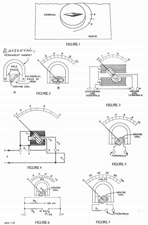
These actions can be used to measure current by means of the simple arrangement shown in Figure 1. A magnetic compass is placed under a wire and as long as there is no current in the wire, the compass needle will line up with the magnetic field of the Earth and point toward the North as shown in the Figure. The wire is then turned until it is parallel to the compass needle and directly above it.
The left thumb rule shows that, regardless of its direction, current in the wire will produce a magnetic field with lines of force that cut square across or at right angles to the compass needle.
Thus, with current in the wire, the resulting magnetic field will tend to turn the compass needle away from its north position. The turning movement of the needle varies with the strength of the electromagnetic field which in turn, varies with the current in the wire.
To make a measuring instrument, or meter, out of this arrangement, the movement or deflection of the needle from its normal resting position must be calibrated by some sort of a numbered scale. To make a scale of this type, a blank sheet of paper is placed under the compass. Then with the circuit arranged so that there is exactly one ampere of current in it, a number 1 is written in line with the compass needle end. Next, the circuit is rear ranged so that there is exactly 2 amperes in it and a number 2 is written in line with the new needle position.
This process can be kept up, in creasing the current in the circuit and marking the points where the needle stops each time, until it is pointing squarely across the wire.
Due to the direction of its lines of force the electromagnetic field is not able to move the needle further.
Reversing the current through the wire will deflect the compass needle on the other side of zero.
Repeating the same procedure that part of the line is calibrated in the same way.
When the marking or calibration is complete, this arrangement can be connected in any circuit and, by watching at which number the compass needle stops, the number of amperes in the wire will be known. This arrangement is the simplest kind of meter and it indicates the presence of electric currents by means of mechanical motion resulting from the magnetic effect produced by the current. Such a device is known as a galvanometer, and since it is calibrated to show the number of amperes in the wire, it also is called an ammeter. However, for everyday use, it would not prove very practical because if the compass was moved closer to or farther from the wire, the reading would vary.
There are a number of other disadvantages to an "open" meter of this kind. For measuring small currents, the magnetic field produced may not be sufficient to overcome the earth's magnetic field. In that case, the reading is highly inaccurate. Furthermore, other magnetic fields like those produced in ordinary house wiring may affect the deflection. It wouldn't be convenient to place such an arrangement for instance in a radio where there may be magnetic fields.
Meters can be built to over come magnetic and other disturbing effects by doing two things: fixing the position of the meter with respect to the current being measured, and making it almost impossible for any outside magnetic field to change the deflection.
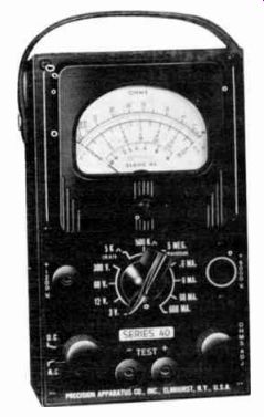
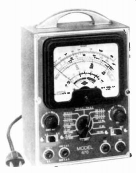
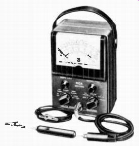
-------------- A handy "pocketsize" multimeter ideal for service
work in the home. Courtesy Precision Apparatus Co., Inc.
D'ARSONVAL METER
One of the most common, and perhaps the most reliable type of meter for direct current measurement is the D'Arsonval, in which a light weight coil of wire, supported on jeweled bearings between the poles of a permanent magnet, is rotated by the effects of an electric current in the coil.
The main parts of a D'Arsonval meter are shown in the sketch of Figure 2A. Here the largest part is a U-shaped permanent magnet, on the lower ends of which are shaped pole pieces of soft iron.
The inner ends of the pole pieces are curved to fit the round or cylindrical piece of iron that is mounted between and quite close to them. This arrangement provides a magnetic path of all iron or steel, except for the small air gap between the pole pieces and the cylindrical center piece of soft iron, and creates a more uniform magnetic field unaffected by out side fields.
The moving coil, which carries the current, is wound on a rectangular aluminum frame that is large enough to fit over the cylindrical iron center piece but small enough to pass between the pole pieces. In order that it can turn freely, the frame is mounted on jewel bearings between the permanent magnetic poles on the general plan of Figure 2B. Thus, the position of the meter always is fixed with respect to the current it measures.
A coiled hairspring is mounted at each end of the frame and a pointer that can swing across a calibrated scale is attached to one end. The hairsprings provide flexible electric connections to the moving coil and at the same time hold the pointer on the "0" scale position when there is no current in the coil.
The entire assembly of moving coil, magnet, hairsprings, pointer, and calibrated dial, when mounted in a case with external terminals, is called a METER MOVEMENT. On the outside of the case, many meters have a small screw head sometimes marked zero set which, when rotated, compensates for slight changes of hairspring tension and resets the pointer to zero on the scale.
With current in the coil, it produces a magnetic field of its own, the N pole of which is repelled by the N pole and attracted by the S pole of the permanent magnet.
The result is a force that rotates the coil against the tension of the springs. Since the strength of the permanent magnet field is always the same and the strength of the coil magnetic field varies with the current, the magnetic pull and resulting rotation varies directly with the current.
The shape of the pole pieces and the cylindrical center piece maintain a uniform magnetic field for every position of the coil.
Regardless of the initial position, the same current change will move the pointer an equal distance, and therefore, the divisions on the scale are equally spaced or linear, as shown in Figure 2B. Since the movement of the coil in a D'Arsonval meter depends on the attraction and repulsion of the coil magnetic poles by those of the permanent magnet, reversing the coil poles will cause the coil to move in the opposite direction. Thus, by reversing the current in the coil, the pointer may be moved in one direction or the other. Making use of this condition, meters may have the "0" of the scale at either end, in the center, or part way between, depending on the desired requirements.
As shown in Figure 2B, most meters have their "0" position at the extreme left and the pointer moves to the right. D'Arsonval movements usually have the correct polarity for a "left to right" swing of the pointer marked on the external terminals and this polarity must be observed when connecting the meter into the circuit.
THE OPERATION OF THE METERS of Figures 1 and 2 IS DUE TO THE INTERACTION OF TWO MAGNETIC FIELDS, one produced by a permanent magnet and the other by current in a wire or coil. The difference is that in Figure 1 the inter action of the fields causes the permanent magnet to move, that is the compass needle, whereas in Figure 2, it is the coil that moves.
A reversal of current in the coil reverses the polarity of the magnetic field it produces, and there fore, its interaction with the field of a permanent magnet is re versed. As a result, the deflection of the compass needle or meter pointer reverses with a reversal of coil current.
ELECTRODYNAMOMETER TYPE METER
An ELECTRODYNAMOMETER is a moving coil indicating instrument in which the stationary magnetic field is produced by a system of fixed coils instead of a permanent magnet. As shown in Figure 3, the stationary or fixed element consists of a pair of coils, L1 and L2, which are connected in series and placed end to end, with a small space between them for the shaft of the moving coil or element. Depending on the application, the fixed coils may be wound with heavy wire for an ammeter or fine wire for a voltmeter.
Pivoted between jeweled bearings, the shaft of the moving element carries coil La which is wound with fine wire and arranged to rotate within the fixed coils. Also attached to the shaft is a light weight pointer which moves over a calibrated scale.
Following the plan of Figure 2B, a coiled hairspring is mounted on each end of the shaft. These springs are adjusted to balance the moving coil mechanically so that, with no current, it will al ways come to rest in a position at which the pointer indicates zero on the scale. Secondly, they provide electric connections between the moving coil and the external circuit. Thus, the springs carry the moving coil current.
The primary application for the dynamometer is to measure the voltage and current at the same time, that is; watts. The single instrument is called a wattmeter and its scale is calibrated directly in watts. The stationary coils L1 and L2 of Figure 3 are connected through terminals 1 and 2 into the circuit in series to measure the current through a part R, while the moving coil L3 is connected in parallel with R, to measure the voltage across it as shown in Figure 4. The resulting magnetic field is a product of current I due to the stationary coils and the voltage E due to the moving coil. Since power is: P=IE the meter measures power in watts.
In Figure 4, the moving coil L3 is wound with fine wire and a series resistor R2 limits the current to a low value. This resistor is chosen so that the current through L3 is a measure of the voltage supplied to RL connected in parallel at terminals 3 and 4.
Resistor R1 is in parallel with the stationary coils to provide a separate current path since the fine wire of these coils would burn out if they handled all of the circuit current. Thus, this resistor serves as a SHUNT since it is in parallel with L1 and L2. The smaller this resistor is, the more current passes through it.
Referring to the circuit of Figure 4, the path of the current is from E - , through component R1, terminals 3 and 2, coils L2 and L1 or shunt R1 , and terminal 1 to E +. From the E - end of RL, there is a circuit through terminal 4, resistor R2, and moving coil L3 to terminal 3. Thus, the magnetic fields set up by stationary coils L2 and L1 are proportional to the current in RL while the magnetic field set up by moving coil L3 is proportional to the voltage drop across R1. Since this wattmeter has four terminals, the proper polarity must be observed when connecting it to a circuit, that is, the positive terminals of both sets of coils must be connected to either the positive side of the circuit or the negative side, but not two different potentials.
When used as a voltmeter or ammeter, L1, L2 and L3 in Figure 3 are connected internally in series as suggested by the broken line and the test leads connect to terminals 1 and 4. Therefore, when the direction of current is reversed, all magnetic polarities are reversed also. Thus, the turning force on the moving coil re mains in the same direction and no reverse readings are possible.
No polarity need be observed when connecting this meter to a circuit and the instrument is suitable for use on both direct and alternating current circuits. In fact, the same scale is used for both d-c and a-c. However, for most applications the D'Arsonval movement is preferred because of its linear scales and accuracy.
AMMETERS
As the name implies, an ammeter is designed to measure current in amperes and therefore, it must be connected in series with the circuit so that all of the current passes through it. This also means that, in order to prevent an appreciable decrease in the circuit current, the resistance of the am meter must be low.
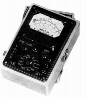
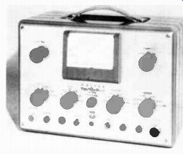
--------------- This multimeter has two sensitivity ratings: 20,000 12/v
on d-c and 1,000 n/v on a-c.
Figure 5 shows a D'Arsonval meter connected as an ammeter.
Each end of the moving coil is brought out to a terminal by means of which the meter may be connected into a circuit.
The range of values that may be measured by a given ammeter depends upon its construction: the number of turns and size of the wire in the coil, the strength of the magnet, the physical size of the coil, and the strength of the springs. To simplify the explanation, assume for the moment that the meter of Figure 5 requires a current of 1 ampere in the coil to set up a magnetic field strong enough to move the pointer completely across the scale. With the pointer in this position, it has FULL-SCALE DEFLECTION, and as shown, a number 1 is placed on the scale at this point. Additional values between 0 and 1 may be located on the scale by adjusting the meter current to the useful values and marking the scale properly at each point. After the scale has been calibrated, all that is necessary to measure any current between 0 and 1 ampere is to connect the meter in series with the circuit and read the current from the scale under the end of the pointer.
Ammeter Sensitivity
The sensitivity of an ammeter is defined as the current required for full scale deflection of the pointer. Hence, an ammeter that requires 1 ampere for full scale deflection is said to have a sensitivity of 1 ampere. A sensitivity of one milliampere means that one milliampere is required for full scale deflection. The most sensitive meter is one that requires the least current for full deflection. On this basis, a one milliampere meter is more sensitive than a one ampere movement.
Ammeter Shunts
In actual practice, often it is necessary to measure currents greater than the full scale range of a given meter. To permit these measurements of higher currents, it is customary to connect a low resistance conductor in parallel with the moving coil of the meter.
When used for this purpose, the relatively low resistance conductor is called a SHUNT. When the meter is connected in the circuit, the current will di vide so that the moving coil and shunt each carry a part. Like any parallel circuit, the current di vides inversely as the resistance of the branches. Therefore, by proper selection, the shunt will carry any desired portion of the total current. As this part re mains always the same, the meter scale can be calibrated to indicate the total current, although the moving coil carries only a definite portion of it.
Shunt Calculations
In Figure 6 is a ammeter, two shunt resistors, and a 3 position switch to select the shunt desired.
In order to illustrate a method of calculating the proper shunt resistance we will assume that the moving coil has a resistance R_m of 50 ohms and requires a current I_m of 1 milliampere (.001 ampere) for full scale deflection.
With the switch in Figure 6 in the 1 ma position as shown, the shunts are disconnected and the moving coil carries the entire current between the - and + meter terminals. Thus, a circuit current of 1 ma causes full scale deflection of the meter pointer.
Turning switch S1 to the 10 ma position connects shunt R3 across the moving coil. This provides two parallel current paths between the meter terminals. With a 1 ma or .001 ampere, 50 ohm moving coil, for a 10 ma range, the resistance of shunt R3 can be found. According to Ohm's Law, E_m is .001 times 50 or .05 volts.
R3 for the 10 ma range has 9 ma or .009 amp through it. Since the coil and R., are in parallel the voltage across them are the same.
Therefore, we know the voltage across and the current through R3. According to Ohm's Law, the resistance of R3 is:
.05 v R,
.009 amp.
5.55 ohms.
Turning switch S1 to the 100 ma position disconnects R3 and connects shunt R4 across the moving coil. For the 100 ma range, the current through R4 is 100 - 1 or 99 ma (.099 amp.). Since the voltage is still the same across the coil for this range, E4 is .05 v and R4 is:
R_4 = .505 ohms.
This is the shunt resistance calculated for the 100 ma range for a 1 ma, 50 ohm moving coil.
It is well to remember here that regardless of its magnitude, the current always divides between the moving coil and shunt in exactly the same ratio. Referring again to shunt R3 of Figure 6, it carries nine times the moving coil current which is one tenth of the total current. As previously explained, with a total current of 10 ma, shunt R3 carries 9 ma and the moving coil, 1 ma.
When the total current is reduced to 8 ma, the moving coil carries .8 ma and the shunt carries nine times .8 or 7.2 ma. Reducing the total current to 4 ma will cause the moving coil to carry .4 ma, and the shunt 9 x .4 or 3.6 ma. In this case, the moving coil always carries one tenth of the total current. This could be indicated directly on the scale by moving the decimal points until the scale reads the total current instead of the current through the coil.
With shunt R, in the circuit, the moving coil carries but one hundredth of the total current.
This could be indicated directly by making the scale of Figure 6 read 0-20-40-60-80-100. By this method of using shunts, very large currents can be measured accurately by a low current meter, the moving parts of which are relatively small and sensitive. Although shunts may be used to extend the range of a meter up ward, they cannot be used to make the meter indicate by full scale deflection a current lower than that for which it was designed.
This can be done only by rewinding the moving coil, a job which usually is more expensive than a new meter of the desired range.
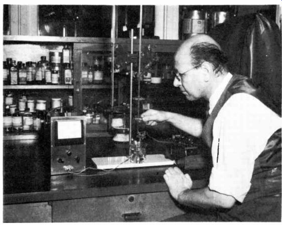
------------ To measure the electric potential of a chemical solution
an ultra-sensitive d-c microammeter is used in this laboratory. Courtesy Radio
Corporation of America
VOLTMETERS
Voltmeters are designed to measure electric pressure and have their scales calibrated directly in volts. The D'Arsonval or moving coil type of meter, described in connection with ammeters and milli-ammeters, may be used in the construction of a volt- meter. However, there are a few things to consider. In the first place, voltage means a difference of potential between two points, such as the terminals of a battery, and to measure it, the meter must be connected directly across the two points.
A second point is that the coil of a D'Arsonval meter is moved by the magnetic effect of an electric current, therefore it is necessary to allow a current in the coil.
Thus, a voltmeter really operates because of the current in it, but the scale is calibrated to read, not the current, but the voltage necessary to cause that current in the coil.
Voltmeter Multipliers Actually, there is little difference between an ammeter and a voltmeter therefore, to simplify the explanation, the meter of Figure 5 can be adapted to operate as a voltmeter. Again let's assume that the moving coil has a resistance of 50 ohms and a current of 1 ma gives full scale deflection.
Connected directly across a source, or other two points of different potentials, the resistance of the voltmeter circuit must be sufficiently high to limit the current to that required for full scale deflection. Therefore, as shown in Figure 7, resistor R1 is connected in series with the moving coil of the meter of Figure 5. In this position in the circuit, It, is known as a "multiplier resistor" or, more simply, a MULTIPLIER. Suppose it is necessary that the voltmeter of Figure 7 read up to a maximum of 100 volts. As one milliampere of current in the moving coil produces full scale deflection of the pointer, the total resistance of R1 and the moving coil must be such that the current is limited to 1 milliampere when 100 volts are applied. Substituting the known current and voltage into Ohm's Law, the total resistance must be:
RT = E/ I =100/.001=100,000 ohms
However, with 50 ohms of resistance in the moving coil, resistor or R1 needs a value of 100,000 - 50 or 99,950 ohms so that the total circuit resistance is 100,000 ohms. Now 100 volts across the terminals causes 100/100,000 or 1 milliampere of current, a value just sufficient to pull the pointer all the way across the scale, and the number "100" can be marked on the scale directly under the pointer tip.
Additional values between 0 and 100 can be located on the scale by applying the proper voltages to the terminals and marking the scale each time. For example, by applying 50 volts, the number "50" can be placed at the point where the pointer stops.
After the scale is calibrated, any potential difference between 0 and 100 volts may be measured merely by applying it to the meter terminals and reading the indicated voltage.
A single range voltmeter is very limited in its scope of use.
If 2 or 3 volts is applied to the 100 voltmeter of Figure 7, the resulting pointer deflection is so small that it is extremely difficult, if not impossible, to read it correctly on the scale. Then too, if 500 volts is applied across the terminals, the resulting current is greater than the full scale rating of the meter causing the pointer to deflect beyond the end of the scale. If the pointer swings hard enough, it will bend or possibly break. In most cases, this excessive current burns out the moving coil.
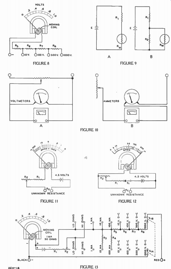
For use on electron apparatus, where voltages ranging from a fraction of a volt to several hundred volts are encountered, a multi-range voltmeter is most convenient. To obtain multi-range operation, a single meter movement is supplied with several multipliers, arranged so that the proper one can be selected by means of a switch or separate terminals. For example, in Figure 8, multipliers R8, R8, R7, and R8 are connected in series between the moving coil and the 1,000 volt terminal. The junctions between the resistors are connected to additional terminals to provide ranges of 10, 100, 500, and 1,000 volts.
The desired voltage range is selected by connecting one test lead into the " - " terminal, which is connected directly to one end of the moving coil, and the second test lead to one of the other terminals. A test lead is a flexible insulated wire with a metal plug on one end and a metal prod mounted in an insulated handle on the other end. It is used as a convenient way of making a temporary connection while measurements are being made.
Voltmeter Sensitivity
With reference to meter movements, the sensitivity is a measure of the current required for full scale deflection. Thus, a meter that requires a lower current to produce full scale deflection of the pointer is more sensitive than a meter that requires a higher current for the same deflection.
For use on electron apparatus, voltmeters employ movements of relatively high sensitivity, since they require little current from the circuit under test and will produce less error in the reading.
Instead of referring to the sensitivity of voltmeters by the current required for full-scale deflection, it is stated as ohms per volt, meaning that the meter circuit must include so many ohms for each volt at full scale.
In the example of Figure 7, the total resistance of the meter circuit is 100,000 ohms for a full scale reading of 100 volts. Thus, its sensitivity is equal to 100,000 ohms divided by 100 volts or 1,000 ohms per volt. A meter movement that operates with less current for full-scale deflection requires more resistance in the circuit, and its ohms per volt rating is higher.
Thus, the greater the sensitivity, the higher the ohms per volt rating of the meter.
As the ohms per volt rating of any meter tells how many ohms the circuit must have for each volt of the full scale reading; it may be calculated by dividing the full-scale current rating of the meter into one volt. That is: Ohms per volt 1 full-scale current
In Figure 7, the meter is a 0 to 1 milliammeter that requires 1 ma for full scale deflection and has an ohms per volt rating of 1/.001 or 1,000. In a like manner, if the movement of Figure 7 re quires 100 microamperes (100 millionths of an ampere) for full scale deflection, the sensitivity rating is:
.000100
-10,000 ohms per volt
Multiplier Calculations
The current to operate a volt meter must be supplied by the circuit under test therefore, to cause the least possible change in circuit conditions, the meter current must be low. For this reason, most voltmeters used on electron equipment employ meter movements that require very little current for full scale deflection of the pointer.
---------- The sensitive electronic voltmeter has little effect on
the circuits being measured. Therefore, more accurate voltage readings are
obtained. Courtesy Radio Corporation of America.
The multirange voltmeter of Figure 8 makes use of the 1 ma meter movement of Figure 6 which has a resistance of 50 ohms and a sensitivity of 1,000 ohms per volt. To demonstrate the multiplier calculations, the resistances of R,„ R6, 117, and R8 will be determined. Although Ohm's Law can be used directly in these calculations, the ohms per volt rating of the meter makes calculations simpler.
Looking at Figure 8, for the 10 I/ range the multiplier is R5, for the 100 y range it is R5 + R6, for the 500 y range it is R5 + Rg + R7.
Finally, for the 1,000 y range it is R5 + R6 + R7 4- Rg. Because R, is a part of all the multi pliers, its value can be found first.
Then R6, R7, and Rs may be deter mined in that order.
Since there must be 1,000 ohms per volt for full-scale deflection, the total resistance between the " - " and "10 v" terminals must be 10 times 1,000 or 10,000 ohms.
The total resistance of a series circuit is equal to the sum of the individual resistances, therefore: or: RT= R.+ R.; = RT - R., = 10,000 – 50 = 9,950 ohms
For the 100 y range, the total resistance must be 100 x 1,000 or 100,000 ohms. From the previous calculation, R., -F R5 was found to be 10,000 ohms, therefore: R.= RT - (Rn, -I- R5) = 100,000 - 10,000 = 90,000 ohms
The same procedure is followed in calculating R7 and R8. Hence for the 500 v range: RT= 500 x 1,000 = 500,000 ohms.
R7= RT - ( R., 12,1- Re)
= 500,000 - 100,000 = 400,000 ohms and for the 1000 y range: RT= 1,000 x 1,000 =1,000,000 ohms.
=RT- (R,„±R5-1- R.+ R,)
= 1,000,000 - 500,000 = 500,000 ohms
METER ERROR
Every meter movement has a small but definite resistance. As has just been described, the current through this resistance produces a small voltage across it.
As an end result, the current meter does affect the circuit being measured and actually a new circuit is created when a meter is inserted.
Shown in Figure 9A is a schematic of a series circuit consisting of R1 , R., and battery E. If the meter resistance R. was zero the circuit would have the same resistance that it had before the meter was inserted. Where E is 50 volts and R 1 is 10 ohms, the current would be 50 divided by 10 or 5 amp.
However, every practical meter does have some resistance. If it were 1 ohm the total circuit resistance would be increased to 11 ohms and the circuit current would be 50 divided by 11 or 4.55 amp. Thus, the meter indicates 5 - 4.55 or .45 amps less than the circuit normally has. This difference is the error introduced by the meter due to its internal resistance.
A similar situation occurs in the circuit of Figure 9B due to the use of a voltmeter. If it was possible for the voltmeter to draw zero current the current in R1 and Ro would be the same since they are in series. However, the meter does draw some current, and thus there is more current in R1 than in Ro and the increased voltage drop across R1 due to this added current means less voltage across Ro. This difference in voltage is the meter error.
For many purposes the meter error is small enough that it can be disregarded. For most purposes it is sufficient to know that the less internal resistance an am meter has, the less error it introduces. Also, the more sensitivity or ohms per volt a voltmeter has, the less current it takes, and therefore, the less error it produces.
CALIBRATING METERS
By far, the easiest and simplest way to test or calibrate a meter is to compare it with a similar meter that is known to be correct.
In Figure 10, two voltmeters are shown at "A" and two ammeters at "B". Notice the main difference is that the voltmeters are connected in parallel, while the am meters are in series. This is based on the fact that all voltages across parallel branches are equal and the current is the same through out a series circuit.
In both cases, the square meter is assumed to be correct and is used to check the calibration of the round one. In order to compare the readings at different points on the scales, at "A", a high resistance potentiometer is connected directly across the voltage source. Then, by changing the position of the movable contact, shown by the arrow, the voltage across the meters can be varied to check their readings at different points on the scales.
However, at "B", both meters and a rheostat type of variable resistor are connected in series across the voltage source. By changing the position of the movable contact, again shown by the arrow, the resistance of the circuit is changed and thus the current is varied to provide readings at various points on the meter scales.
OHMMETERS
In addition to measuring the voltage and current, often it is necessary that the resistance of a circuit or part be known before it is connected to a voltage source.
Resistance may be measured by several methods, but the most simple and popular one is to use a meter that reads directly in ohms.
-------------- The electronic voltmeter above can be used for voltage,
resistance, and capacitor measurements. Courtesy Superior Instruments Co.
Ohm's Law states that the resistance of a circuit is equal to the applied voltage divided by the resulting current. Thus, if a known voltage is applied to a device and the electron flow is measured with a current meter, the resistance can be calculated. In fact, if the same voltage is used for all tests, the resistance readings can be printed on the meter scale instead of the current readings. When the scale is calibrated directly in ohms in this way, the instrument is called an OHMMETER.
The ohmmeter circuit shown in Figure 11, includes the same meter movement that was used in Figures 5, 6, and 7 with the exception that the meter scale now is calibrated directly in ohms.
The circuit includes a battery as a voltage source, the moving coil of the meter, fixed resistor R1 , variable resistor R., and two external terminals. When an unknown resistance, R., is connected across the terminals, a series circuit is completed and the resulting current causes a deflection of the meter pointer.
As the meter requires 1 ma, (.001 ampere) for full scale deflection and a 4.5 volt battery is indicated, the circuit must include 4,500 ohms of resistance to pre vent excessive current when the R. terminals are shorted. The total resistance consists of that in the moving coil, fixed resistor R1 and variable resistor R.». Known as the ohmmeter Ohm's Adjust or Zero Adjust, resistor R2 is variable to compensate for voltage variations as the battery ages.
Although a single variable resistor could be used in place of R1 and R2, its adjustment would be extremely critical because of its wide range. With the arrangement shown, a fixed resistor of approximately 3,500 ohms, the meter resistance of about 50 ohms and a variable resistor of 1,000 ohms are placed in series. Thus the circuit resistance can be varied from slightly above to about 1,000 ohms below the required value during complete rotation of R. and so the adjustment is not critical. Moreover, by having 3,500 ohms fixed in the circuit, the possibility of an excessive current burning out the meter movement is reduced.
The terminals marked "unknown resistance" are in series with the battery, moving coil, and variable resistors. If the terminals are shorted and the circuit adjusted to place the 4 1/2 volts across 4,500 ohms of resistance, by Ohm's Law, this condition will allow 1 ma, of current and the pointer moves all the way across the scale. Since the unknown resistance R. is zero ohms, a "0" is marked opposite the pointer at the right end of the scale.
Now suppose a resistor of 1,000 ohms is connected across the R. terminals. The total resistance of the meter circuit will be increased from 4,500 to 5,500 ohms, and the meter will indicate a current of 4.5/5,500 or .000817 amperes (.817 ma). However, when calibrating the scale, 1,000 is marked at this position since 1,000 ohms is the resistance added to the circuit. In the same way, resistances of 2,000, 5,000, 10,000, and 500,000 ohms, can be connected across the terminals and their resistances marked on the scale at the point where the pointer comes to rest when each resistor is in the circuit.
As shown in Figure 11, "0" is at the extreme right of the scale, with the numbers increasing to ward the left and becoming more crowded as they approach the left end of the scale. At the extreme left, the resistance is read as "in finite" and is represented by the symbol for "infinity" which resembles a number 8 resting on its side. An infinity resistance reading is given by either an open circuit or a resistance well beyond the range of the meter.
The circuit shown in Figure 12 often is referred to as a BACK-UP OHMMETER. It receives its name from the fact that when resistances are measured, the pointer moves in a direction reversed to that explained for Figure 11.
To obtain back-up operation, the 4.5-volt battery, the meter movement, resistors R1 and R2, and switch Si are all connected in series, and the R. terminals are attached to each end of the moving coil. With this arrangement, any resistor connected between the R. terminals is shunted across the moving coil and reduces the meter reading. Switch S1 is included so that the circuit may be opened to prevent the battery from discharging when the meter is not in use.
With the switch closed and nothing connected between the Rx terminals, the circuit is the same as that of Figure 11 with the Rx terminals shorted. Thus, there is full-scale deflection of the meter hand and the "infinity" symbol is placed at the right end of the scale.
Assume as before that the moving coil has a resistance of 50 ohms and requires a current of 1 ma for full scale deflection. Then, with a 50 ohm resistor connected across the R. terminals, the circuit current of 1 ma will divide equally between the moving coil and resistor.
Thus, with a moving coil current of 1A or .5 ma, the pointer will stop at the .5 division on the scale which can be marked 50, for in this case the "unknown resistance" is 50 ohms.
This is an interesting point to remember. The center marking on any "back-up scale" ohmmeter indicates the internal resistance of the moving coil unless shunts are internally connected across the moving coil. In that case the center scale marking is the resistance of the combination.
An ohmmeter of this type is calibrated exactly the same as explained for Figure 11. However, due to the fact that the resistance of the moving coil is comparatively low and that it determines the mid-scale value, the circuit of Figure 12 is used mainly for the measurement of low resistances.
On the back-up ohmmeter scale, the resistance readings appear just opposite to that of the ohm meter of Figure 11. Here, "0" ohms is at the left while infinity is at the right. Moreover, on this scale, the numbers are comparatively far apart near the left end and crowded at the right.
The circuit of Figure 11 is more flexible, as the resistance ranges can be varied to take care of any practical measurements. The ranges depend not only on the sensitivity of the meter movement, but also on the supply voltage. Although a battery is shown, any other source of d-c voltage may be employed. For example, in a number of commercial units, a high voltage d-c supply is obtained from an a-c power outlet by employing a rectifier built in as a part of the ohmmeter circuit.
Before making tests, the terminals of the ohmmeter of Figure 11 are shorted and variable resistor R2 is adjusted until the meter pointer indicates exactly "0" ohms on the scale. Then the short is removed and when connected to the terminals, the unknown resistance R. will be indicated on the scale.
For the back-up meter of Figure 12, the R. terminals are left open and, with switch S1 closed, resistor R2 is adjusted until the pointer deflects full scale to the infinity mark. Then, when connected across the R. terminals, the unknown resistance is indicated on the meter scale.
A COMPLETE MULTIMETER
Now that the various applications of a meter movement have been explained, in Figure 13 the individual circuits are shown combined to form a single multirange volt-ohm-milliammeter otherwise known as a multimeter. Provisions are made for the separate measurement of d-c voltage, current, and resistance with four ranges for volts, three ranges for milliamperes and two for ohms.
A nine position selector switch connects this basic meter movement to the necessary circuits for the desired ranges. Since only one meter movement is used, it must be equipped with a dial face which includes all of the scales required for the individual ranges.
The circuits incorporated in this multimeter are those covered for the milliammeter, voltmeter, and ohmmeters of Figures 6, 8, 11 and 12. Any one of these circuits, may be selected by the 9 position switch S1 , which is of the rotary type with a knob attached to the shaft. Turning the knob causes the two contacts, S1A and Sin, to move in unison and make connection to the various points indicated by the small circles in Figure 13.
In the position shown, the meter circuit is in the 0-1000 volts d-c range and the four multipliers
------------ Combination electronic voltmeter can be used to measure
current, voltage, resistance, and capacitance. Courtesy Radio Corporation of
America.
R5, R6, R7, and Rs are in series with the meter movement exactly as explained for the circuit of Figure 8. The circuit can be traced from the Black "-" terminal through the moving coil, resistors R,„ Rs, R7, and Rs, and contact Sin to the Red " + " terminal.
Although the ohmmeter sections for both "hi" and "lo" ohms were described for Figures 11 and 12, a brief review of them along with an explanation of the modification introduced in this multimeter circuit may be of benefit.
With the switch contacts S1, and S1 in the "hi ohms" position, there is a circuit from the black terminal through the moving coil, through the battery from " + " to " -", through resistors R1 and R2t through the "hi ohms" and S1 . contacts to the red terminal. This is the circuit of Figure 11 except for the slightly different positions of the battery and resistors.
The "lo ohms" section of the multimeter contains a back-up ohmmeter similar to that of Figure 12. With the selector switch in the lo ohms position, the red terminal is connected through S1 . to the "+" terminal of the moving coil and battery, while the moving coil " -" and the black terminals are connected through S1, to R2. Thus, the moving coil, R; arid R2 are placed in series across the battery and the red and black terminals are connected directly to the moving coil.
The example of Figure 13 is a very common multimeter circuit and it can be found in many commercial units on the market. With an 0-1 ma meter in its circuit, it is called a 1,000 ohms per volt instrument.
VACUUM TUBE VOLTMETER
We pointed out earlier in the lesson how the insertion of a meter in the circuit changes the circuit conditions sufficiently to give a reading different from the actual operating conditions.
For now it is sufficient to know that the more sensitive the meter circuit, the smaller the error. However, sensitive meter movements are costly and very fragile.
Even though a meter movement operates satisfactorily within its design limits, it can be damaged readily by mechanical shock or accidental overloads.
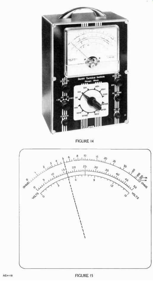
One method to reduce error and at the same time have an economical, rugged multimeter with a D'Arsonval movement for troubleshooting purposes is to use a circuit which includes one or more electron tubes. Such a meter is called a vacuum tube volt meter (VTVM) or an ELECTRONIC VOLTMETER. The use of the VTVM is very similar to the multimeter and as shown in Figure 14, there are only two added controls. The on and off switch mounted on the "Ohm's Adj." control is needed to turn off the internal circuit when the meter is not in use and the zero adj. is needed to adjust the tube circuits to give a zero meter reading.
On the particular meter shown here, the range selector and function switches are shown separate instead of combined into one switch as used in the multimeter circuit of Figure 13.
The FUNCTION switch, located below the Zero Adj. on the left, selects the necessary internal circuits to measure d-c, a-c, and ohms. The desired range of the meter is selected by the RANGE switch located centrally below the meter face.
Below the Ohm's Adj. is the panel jack for the lead used for both AC and ohms measurements.
Below it is the panel jack used for both d-c and r-f voltage measurements. Measuring high frequency a-c or r-f voltages poses new problems which are described later in your program. On the left side at the bottom is the common jack where the common or ground lead plugs into.
The common, d-c-r-f, and a-c ohms test leads connect to the three meter terminals. The common test lead is merely an insulated wire with a convenient handling prod. The a-c and ohms lead is an insulated wire with test prods just like the common. The d-c lead is used for both + and - d-c measurements and in some models has a resistor inside the test prod. For ease in recognition, this test lead may be colored red. However, before considering the internal circuitry further, let's see how the meter is used.
READING THE SCALES
On the face of this VTVM meter are three scales which are shown in Figure 15. Starting at the top, we find a non-linear scale which is the Ohm's scale. Beginning with "0" on the left and ending with "co" on the right, the Ohm's scale is identified by the words "ohms" at either end.
Normally in a VTVM of this type, the same scales are used for both a-c, and + or - d-c voltages.
This is the reason why only "volts" appears at either ends of these scales. The upper volts scale goes from 0-5.0 while the lower extends from 0-15. Many VTVM's use colored scales for ease in distinguishing one scale from an other.
With the function switch in the ohms position and the range switch set for the R x 1, the pointer indication is multiplied by one, or more simply, read as indicated on the ohm's scale. Switching to the R x 10 range, the pointer directly over the 5 on the scale is 5 times 10 or 50. Switching to the R x 100 range the reading with the pointer still on 5 is 5 x 100 or 500. With the pointer still at 5, and the range switch successively changed to R x 1,000, R x 10K and R x 100K, the readings be come 5,000, 50K, and 500K. With the function switch set at either + or - d-c or a-c the various possible ranges are 5, 15, 50, 150, 500, and 1,500. For 5, 50, and 500 volts the upper scale is more convenient since the multiplying factors are 1, 10 and 100. The lower scale is better adapted for reading 15, 150 and 1,500 since the multiplying factors are 1, 10, and 100. Briefly, the multiplying factor for the range selected is found by dividing that range selected by the maximum scale reading. For instance, if 50 were the chosen scale and 500 is the range, then the multiplying factor is:
500 / 50 =10.
ZERO PROCEDURE
As far as using the VTVM, there are two "zeroing" knobs to adjust: the Zero Adjust at the upper left and the Ohm's Adj. at the upper right. The Zero Adj. procedure is the same for each function when it requires it, while the Ohm's Adj. is required only for ohmmeter readings.
With the function switch set for ohms, and the range switch in one of the six positions, before any resistances are measured touch the ohms and common lead together and with the Zero Ad just, position the pointer directly over the zero on the ohm's scale.
Separate the leads and let the pointer swing back to the right.
If the pointer does not rest over the " oc" mark on the right, turn the Ohm's Adj. until it does. Al ways start by using the Zero Adj., since there is some interaction between the two when the Ohm's Adjust is used first. Having completed the zeroing, you can now measure resistances, but be sure all voltage sources are turned off.
When the function switch is in + d-c, - d-c, or a-c, the pointer may not rest on zero. In that case the proper leads, common and d-c or common and a-c are touched together and the pointer is positioned over zero by the Zero Adj.
It may not always be necessary to touch the leads together, but since voltages present in nearby equipment produce strong magnetic fields, these may induce enough voltage into the test leads to give an incorrect zero adjustment.
For the a-c, polarity need not be observed, but a good procedure is that the common of the VTVM should be connected to the common or chassis of the equipment under test.
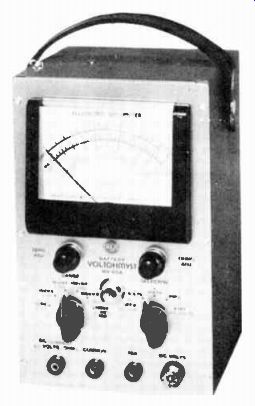
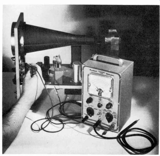
----------- To obtain correct readings of low voltages across high resistance,
a vtvm is used. Courtesy Precision Apparatus Co.
POWER SUPPLY
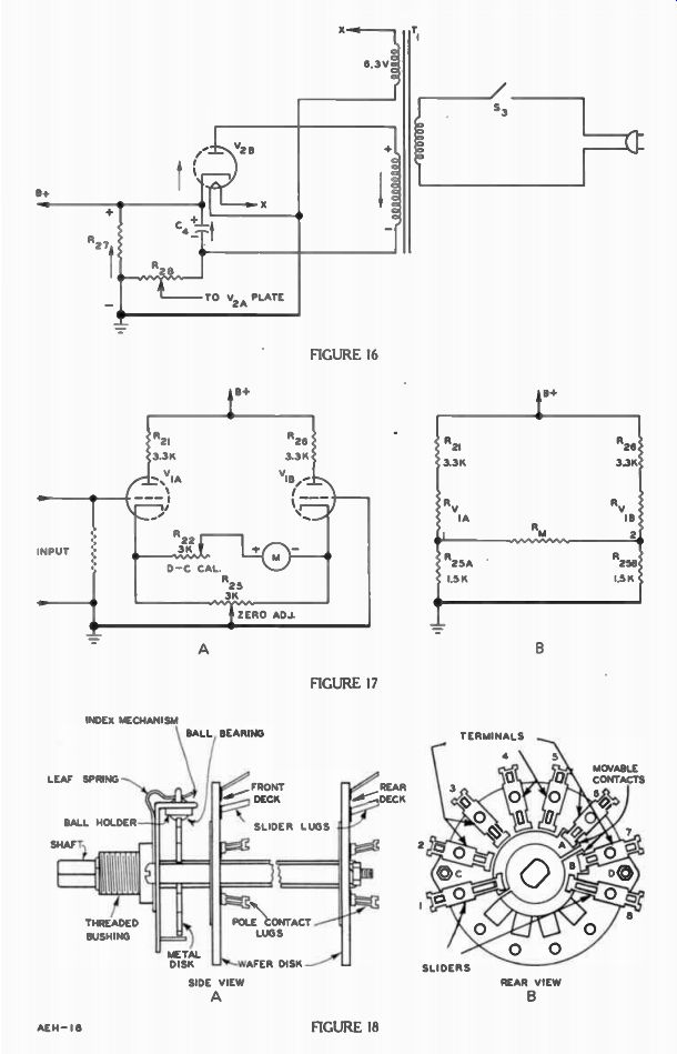
Since the vacuum tube voltmeter has electron tubes in it, one of the main meter circuits is a power supply and practically all VTVM's of the type used in lab oratories and service work contain a built-in power supply similar to Figure 16. Note that it uses a half wave rectifier.
The primary circuit of T1 is completed with the power line when switch S3 is closed. Normally this switch is operated by the Ohm's Adj. knob. Transformer T1 has two secondaries, one for supplying the high voltage to rectifier tube V2 and the other for the filament winding providing 6.3 volts a-c to the tube heaters.
The high voltage of T1 is applied at the plate of V28 and the negative side of C4. Remembering that the ground symbol indicates points of the same potential, R27 and R28 are really connected together. This places R27 . and R28 in series with each other and in parallel with C4. When the alternating voltage is such that the plate of V28 becomes positive, tube V28 conducts from cathode to plate.
Electrons flow from the - of T1 through R2s, then through R27, to the cathode of V2B, inside the tube from cathode to plate, to the 4 end of T1 and then back to its - end. At the same time electrons flow through R27 and R28, C4 is charged to the polarity indicated.
During the negative alternation, V2B does not conduct. Some of the charge on C4 discharges through R..7 and R28, but since R.,7 is 47,000 ohms this discharge is slow and most of the voltage across C4 still remains when the following positive alternation charges C4 back to its full voltage.
Since R.8 is only 1,000 ohms, which is small compared to 47,000 ohms for R27, the voltage developed across R28 is small compared to the voltage across R27. More over, the direction of the current through R28 is such that the end connected to the capacitor is negative and its grounded end is positive. Thus, with ground as the reference, across R.8 is a small negative voltage, part of which is fed through the slider to tube V2A. At the same time the larger positive voltage across R27 serves as B + for the other circuits.
BALANCE AMPLIFIER
The heart of most VTVM's is the balance amplifiers shown in Figure 17A and the resistor circuit of Figure 17B can be used to explain the basic action. The same symbols and values are used in both diagrams except for one or two changes. In Figure 17B, R. represents both the meter resistance and that of R22, and R28 of Figure 17A is divided equally in Figure 17B and labeled R25, and R25B ; both 1.5K ohms. RV 1 A and R,18 each represent sections of the tube V1A and V1B. Also the in put grid resistor to V1 is not included since it is not part of the tube plate. Initially, let's suppose R. is not connected in the circuit and so we have two circuits in parallel. Thus, R21, RV1,, and R25, form one branch and each has an equal resistance in the other parallel branch labeled R28, RV1B, and R25B. With a complete circuit from ground to B +, by Ohm's Law an equal current exists through both circuits since their resistance and voltage are the same. Thus, the voltage across R.,5A is identical to that of R25B, and for the sake of description let's assume it to be 6 volts. There fore, points 1 and 2 are each + 6 to ground.
As a result, the potential difference between points 1 and 2 is (6) - (6)=0 v. Thus, even with R_m in the circuit there would be zero volts across it and without voltage across lt,„ no current exists through it. The circuit is "balanced" when no current passes through It,„.
Suppose resistance Ri-1,, decreases so that the total resistance in that leg decreases. Then the current in the left branch is greater than in the right branch.
With this in mind, the voltage across R25 is greater than 6 y since there is more current through it. Suppose the voltage increases to 7 v. Hence, point 1 is 7 v - 6v or 1 v positive with respect to point 2 and there is a current through the meter. In this condition, the circuit is said to be "unbalanced". So long as the resistance change in the left branch is not too great, with the Zero Adj. potentiometer R25 of Figure 17A, the circuit can be "zeroed" or balanced as before by making Ro5A enough different than Rq58 to equalize the voltages across them.
Thus, we see how the Zero Adj. in Figure 17A balances the amplifiers so that there is no current through the meter or R2.) when there is no signal on the grid of ViA. The input grid resistor to VIA ties the grid to ground and since normally there is no current through it, ViA grid is at ground potential. However, when a voltage is applied to the input, the voltage across the grid resistor appears on the grid of V1 and so the original bias for the tube is changed. When a positive voltage is placed on the grid, it is less negative and this reduces the internal resistance of tube Vim thereby unbalancing the amplifiers. More current flows through the cathode resistor of V1, (R23) which makes its voltage more positive with respect to ground.
With a difference of potential now existing between the cathodes, current passes through R22 and the meter. The current deflects the pointer, and the scale is calibrated to indicate whatever was applied to the input.
Resistor R-, the d-c calibration resistor, is adjusted until the pointer indicates the standard voltage used to adjust the instrument. This is done for only one d-c voltage range. For a-c voltages R. is replaced by R23 of Figure 22. This makes it possible to calibrate the meter for a-c voltages in the same manner.
The main purpose of these Calibrate and the Zero Adj. controls is that, as the parts age including tubes, any resistance changes easily can be compensated for with out any component replacements.
Whenever necessary, the meter can be quickly and accurately calibrated.
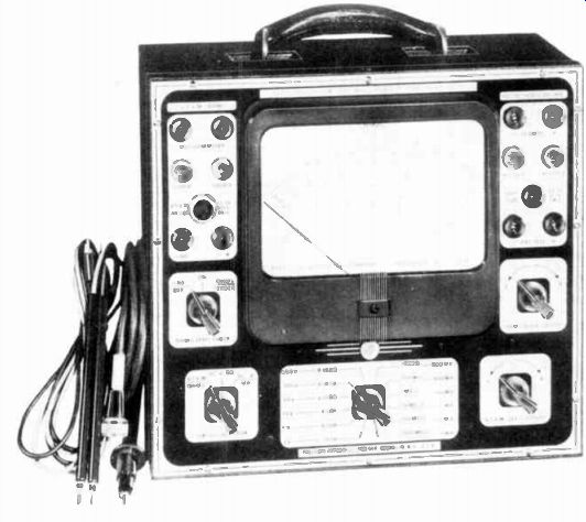
----------- The vacuum tube voltmeter is being used to measure a-c
voltages in an oscilloscope which is used in dynamic testing. Courtesy The
Heath Co.
INPUT CIRCUITS
The VTVM has three main di visions: a power supply, balance amplifiers, and the input circuits needed to produce the necessary ranges and functions for the me ter. The balanced amplifier was described in Figure 17, the power supply that supplies the B + and heater voltages for this amplifier circuit were described in Figure 16. What remains is the input circuits.
By taking a quick look at Figure 22, it is easy to see that the major components in these input circuits are switches and resistors.
In this particular circuit there are two wafer switches, S1 and So. S1 is the function switch and it has three Wafers, S1 „ SIB, and S1 ,. The range switch 52 also contains three wafers, S2 „ S 2 B, S 2 c.
A good idea of how these switches work can be secured by looking at the two wafer switch in Figure 18.
As shown in the side view of Figure 18A, the index mechanism and the wafers all mount on the same shaft. The index consists of a ball bearing pressing against the edge of a notched metal disc.
This makes sure that the switch remains in position until rotated by the operator and then it moves by steps from one position to the next, never stopping half way between two positions.
Each wafer is a disc made of bakelite or a similar insulating material on which the terminals and sliders are riveted. The bakelite discs are held rigidly in position by posts running through the holes labeled C and D in the rear view of Figure 18B. A smaller disc, free to rotate, is mounted on the shaft so that it moves between the large wafer and the contacts on the wafer. On this rotating disc are semi-circular conductors and the movable contacts are projections of these areas, labeled A and B. These reach out far enough to make contact with the terminals. The sliders are long enough to contact the semi-circular areas directly and therefore, do not depend on the switch position.
For example, in the position shown in Figure 18B, slider 8 connects to B and B is making contact with terminal 7. In like manner slider 1 connects to A which is making contact with terminal 6. Now if the switch was moved one position in the counterclockwise direction, A would contact 5 and B would contact 6.
Therefore slider 1 would connect to 5 instead of 6 and slider 8 would connect to 6 instead of 7.
The actual number of sliders and terminals on each wafer of a switch are determined by the particular need of the switch. In Figure 22, the schematic diagram shows each wafer for the two switches separately so that 6 wafers are clearly in view. A quick glance will show differences even between wafers on the same switch. For example, although S2, and S2, each have six terminals, S2, has 12 terminals. Again S, has one slider and 3 terminals, S1 has one slider and 5 terminals, and SIC has 2 sliders and 8 terminals.
In order to describe the input circuits accurately each one will be traced carefully in Figure 22 and then redrawn for explanation in a separate Figure. In Figure 22 the function switch is shown in the a-c position. When we tr:1^e the d-c voltmeter and ohmmeter circuit, be sure to remember these circuits are completed by the function switch when the meter is used for that purpose.
D-C Input
For the + d-c setting of the function switch we can trace the complete path from the d-c lead to VIA for the 5 y range because the movable contacts on Si„, Si E, and Sic connect with the +d-c terminals instead of the a-c terminals as shown. From + terminal of the voltage being measured, through the test lead through J 3, through Ro, to the + d-c terminal on Si „, and when this switch is in the + d-c position, from the slider on Si, to terminal 1 on S28.
From her - e it connects to the slider arm on 52,, to d-e or terminal 2 on Si ., to the slider arm on SIB, and through R14 to the grid of « VIA. From terminal 1 on S 2,, the resistors R8 through R13 are connected in series to ground. The common lead connects the - end of the voltage source to R13 through J 1, on the VTVM chassis.
As the range switch is advanced, the protruding contacts A, B, and C on the three wafers touch different terminals, while each "slider" arm connects to contacts A, B and C by means of the curved bar. The function switch Si contacts do not change from the + d-c position for changes in the ranges.
As shown by redrawing this portion of the circuit without the function switch in Figure 19, the voltage to be measured is applied through the d-c test lead, J3> R2, and R1 , to the grid. The voltage to be measured is represented here by a battery. The common lead connects the negative end of the battery to the VTVM chassis. In this case R2 and the Sou resistor string form a complete series circuit with the battery and the current makes Point B positive with respect to ground. Since no current passes through Ri ,, the grid of V1 , is at this same positive potential. Referring to Figure 17, the positive grid makes V,„ conduct more current. Assuming the amplifiers were already zero adjusted, the added current through R25 increases the voltage across it, making the cathode of VIA more positive. The cathodes then have a difference of potential and current passes through meter M and R22.
To measure negative direct voltage, the function switch is set to the -d-c position. With this setting, the input circuits remain as they were for the + d-e position. However, the cathode of V,8 now connects through terminal 3 of Sic and the lower slider to the + terminal of the meter. Vari able resistor R22 connects through terminal 7 and the upper slider to the - of the meter. These connections to the meter are just the opposite of those shown in Figure 17. That is, in Figure 17, the meter + and - terminals should be interchanged to indicate the connections for measuring negative direct voltage.
-------- Here the direct probe plugs into the d-c probe, thereby eliminating
a third lead. Courtesy Radio Corporation of America
Also, if the polarity of battery E were reversed, Figure 19 would illustrate the proper connections of the test leads for measuring negative direct voltage. That is, the d-c lead is placed at the negative terminal of the voltage source, and the common lead at the positive terminal. These connections make J 3 negative with respect to J1 or ground. This negative voltage is applied through R2 and R14 to the grid of V1 A. Referring again to Figure 17, with its grid more negative, VIA conducts less. With smaller plate current in this tube, the voltage across the left section of R03 is smaller. Therefore, the cathode of V1, is less positive than that of Virt . With the cathodes at different positive potentials with respect to ground, current is produced in the meter circuit. In this case, electron flow is from the left end of R23, through It- and meter M, to the cathode of In either d-c position, higher ranges are selected by turning switch S2 in Figure 22. Contact B on Soi , successively makes contact with points 2, 3, 4, 5, 6. As higher voltages are measured on these ranges, a smaller portion of the total voltage must be applied to the grid of VIA for full scale deflection.
For example, in Figure 19 on the 1,500 volt range contact B is at terminal 6 instead of terminal
1. R2, R13, and the voltage source form a series circuit but only that portion across R13 is applied to V1 . Since the resistance of R13 is 18K ohms and the total resistance is over 10 megohms, only a small portion of the 1,500 volts is applied through R14 to the Vij , grid. On the other hand for a 150 volt range, contact B is on terminal 4. Now the voltage across R11 , R12, and R13, is applied through R14 to the grid of V1 A. Since this is 10 times the resistance, it gives the same deflection for one tenth the voltage. Thus, the 150 volts now applied give the same meter deflection as 1,500 volts on the 1,500 volt range.
A-C Input
In Figure 22, the a-c input circuit can be traced through the a-c ohms test lead, to J2, through C1 and R3 to S2 , terminal 1, to the sliding contact arm of S2 C2 and R7 to terminal 1 of S1,. From the contact arm of S1A, to ' S2B terminal 1, S2c terminal 1, Soc con tact arm, S1 . terminal 4, S1 . con tact arm, - and finally through R14 to control grid of V1,. R4, Rs, R6, are in series from terminal 1 of So, to ground. Also, from terminal 1 of S2., resistors R8, R9, R10, R11, R1 °, and R13 axe in series to ground. Tube V2A also is part of the a-c input circuit.
This input circuit is drawn without the function switch S, in Figure 20. The numbers refer to the terminals on switches SoA and S2c . Mounted on S.., resistors R8 through R13 connect to S2c as shown.
Points A and C indicate the movable contact that moves along the various terminals for other ranges when the range switch is rotated.
The purpose of the a-c input circuit is to convert the measured a-c voltage to a positive d-c for the grid of VI,. If an alternating voltage were Placed on the grid, then the current through the meter in the balance amplifier would follow this variation causing the pointer to oscillate. There would not be a stationary indication to read on the meter scale.
To avoid this fault, the entire circuit up to point C is required, and R1 , and capacitor C3 filter out any ripple before it reaches the grid of V1,. In addition R14 protects VIA from damaging current should the grid become positive with respect to the cathode. When no voltage is being measured the grid has a zero voltage with respect to ground but a negative voltage with respect to the cathode since the cathode is positive with respect to ground as explained in Figure 17A. Therefore, under normal conditions, a positive voltage at point C makes the grid positive with respect to ground but less negative with respect to the cathode, and does not produce grid current. However, a very large positive voltage could exceed the cathode bias and cause the grid to draw current. In this case, the resistance of R14 limits the current to a safe value.
When the function switch is placed in the a-c position with the a-c and common leads connected across an a-c voltage, the meter should indicate just this voltage.
In some circuits, d-c may be present, and to keep the meter from reading it, it is blocked by C1.
This places C1 , R3, and the entire S2A string in series across the a-c voltage being measured.
Without any voltage being measured, since the cathode of V2 is connected through R7 and the S.. resistors to ground, the cathode should be at ground potential. However, since these resistances are very high, a very minute current caused by electrons striking the grid of V1A it makes the cathode of V2A slightly' negative with respect to ground.
Therefore, an equal negative voltage must be applied to the plate of V,„ to keep the tube from con ducting except when an a-c voltage is being measured. As explained in Figure 16, this voltage comes from R28 in the power supply.
When an a-c voltage is measured, capacitor Co couples the voltage between point A and ground to the cathode of Vo, and the string of resistors in S2 B. When the negative alternation is applied to the cathode, the plate is more positive than the cathode and V2A conducts. As a result, current passes through the resistors in So, into C2 and from C2 through the tube thus charging the cathode side of C2 positive.
Only a little current passes through R7 and the resistors on S2B, since the total resistance of this series is very large.
On the positive alternation of a-c source, tube Vo„ does not con duct since the positive voltage, applied to the cathode, makes the plate negative with respect to the cathode. Capacitor C2 will discharge very little through the high resistance path of the S 2 B resistors and R7 during the positive alternation. Thus, a fairly constant d-e is applied to point C. Finally, R7 lowers it to the value needed to unbalance the amplifiers and cause proper deflection of the pointer. This voltage is applied to the grid of V1„ through R14.
For the 15, 50, 150, 500, 1,500 v a-c ranges S 2A and S 2 c are switched to terminals 2, 3, 4, 5, 6, and on terminals 5, and 6 a smaller portion of the measured voltage is rectified by V2A and passed to the grid of VIA. This keeps the voltage applied to V2A on the high voltage ranges from exceeding the tubes voltage limitations.
Ohms Input
The ohms input circuit is placed into operation when the function switch is placed in the Ohm's position. In Figure 22, the ohms lead connects through J2 to terminal 5 on S1 .. When the function switch is in the ohms position the movable contacts connect to terminal 5 and terminal 1.
Therefore, the circuit is completed through terminal 1 to the contact arm of Soc, and in the R x 1 position, movable contact C connects through terminal 12 to R20 and battery E. The slide contact on SIB connects to the grid of V1 A through R14.
The ohms input circuit on the R x 1 range is shown in Figure 21, without all the switching. To measure the resistance of some resistor R., connect the ohms and common lead across it after being sure all of the external voltage is turned off and no other part is in parallel with it.
Keep in mind that there is a connection from the common jack through the chassis to the grounded end of the battery. R. completes a circuit which includes R20 and the battery E. Current passes from battery negative through R., through R20, and to battery positive. The voltage from point 12 to ground is positive since it is the battery voltage minus whatever appears across R20. This positive voltage at point 12 makes the grid bias for V1, less negative. This reduced bias upsets the amplifier balance, and the current through the meter deflects the pointer.
Since the unknown resistance R. is in series with R20 and the battery, when R. is equal to R20 or 10 ohms, half of the battery voltage appears across R. and is applied through R14 to the grid of V1A. If a larger unknown resistance is used a larger portion of the battery voltage is applied to V1A and this causes a larger meter' deflection.
When the range switch is rotated to new range positions new resistances replace R20. For example in the R x 10 position, R19 which is 100 ohms replaces R20 in the circuit. Therefore to have the same voltage across it and cause the same meter deflection R. has to have 10 times the resistance.
Hence, the readings are properly multiplied by 10. The same holds true for each other position of the range switch, the resistance that replaces R20 determines the multiplying factor.
Note that on R x 100K, the highest range, the resistance, R20 is replaced by R15 which is 1 meg ohm as shown in Figure -22. If this range is used to measure a small resistance hardly any voltage appears across it. Thus, the grid bias on V1A is changed so slightly that little or no pointer deflection occurs. To measure this small resistance, you must switch to a lower range.
VTVM Rating
Unlike other meters, the VTVM is not rated by its ohms per volt sensitivity. As was pointed out earlier, the more current the meter draws, the more error a volt meter has. The higher the input resistance of the meter, the less current drawn, and the less error.
Moreover, unlike multimeters, the VTVM input resistance does not change for the various ranges.
For example, the voltage being measured is applied to resistors R2, Rs, R9, R10, R11, R12, and R13 in series for all d-c ranges of the VTVM. Therefore, it is common practice to rate VTVM's according to their input resistance since it is this resistance that determines how much current is drawn by the meter. The higher this resistance, the better the meter; all other things being equal.
A typical input resistance is 10 megohms. By adding the values shown in Figure 22 for these resistors, this meter input slightly exceeds 10 megohms.
SUMMARY
Basically, a meter operates on the magnetic effects of an electric current.
The meter movements described in this lesson operate due to the interaction of two magnetic fields. A pointer is attached to a moving coil which deflects.
The stronger the magnetic field the greater the deflection.
To prevent a reduction of circuit current the resistance of an ammeter must be low. But to limit the current used for the operation of a voltmeter, its resistance must be high.
The greater the current required for full scale deflection of an ammeter, the less its sensitivity. An instrument which requires a small current for full scale deflection has high sensitivity. Selected resistors, called shunts, are connected across the terminals of an ammeter to extend its current range upward.
Voltmeter sensitivity is expressed in ohms per volt, and is found from: 1 Ohms per volt full scale current
Selected resistors, called multipliers, are connected in series with the meter movement to extend the voltage range upward.
There are two basic ohmmeter currents: one is known as the series type in which the unknown resistance is placed in series with a meter, a battery and a limiting resistor. The decrease of current in the circuit is a measure of the added resistance. The scale markings of this type of ohmmeter decrease from a high resistance to zero resistance for full scale deflection of the pointer.
The second basic ohmmeter circuit is the back-up or shunt type in which the unknown resistance is placed in parallel with the meter movement. In this type, the current through the meter is an inverse measure of the shunt resistance. The scale markings of this type ohmmeter increase from zero to a high resistance for full scale deflection of the pointer.
A single multirange instrument, known as a multimeter, includes circuit arrangements for measurement of a-c d-c voltages, direct current, and resistance. Similar in function to a multimeter, a vacuum tube voltmeter includes vacuum tubes and circuit arrangements which increase the accuracy of the instrument and make it less liable to damage on accidental overload.
A VTVM usually is rated according to its input resistance. A typical rating is 10 megohms.
IMPORTANT DEFINITIONS
D'ARSONVAL-[dahr son VAHL]-A type of direct current meter in which a lightweight coil of wire, supported on jeweled bearings between the poles of a permanent magnet, is rotated by the effects of an electric current in the coil.
SENSITIVITY-[sen si TIV i ti]-As pertaining to meters, a measure of the current required for full scale deflection. For a volt meter it is expressed in "ohms per volt". VACUUM TUBE VOLTMETER-A circuit using a balancing circuit, which measures a voltage when the circuit is unbalanced.
WATT METER-[WAHT mee ter]-An electric instrument calibrated directly in watts and used for power measurements.
WORK DIAGRAMS
-----------
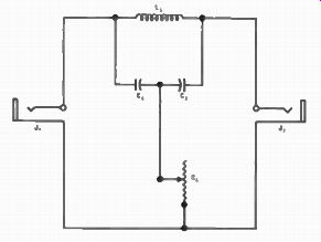
1. The drawing shows a circuit consisting of an iron core inductor, two capacitors, a variable resistor, and two jacks mounted in a chassis. Draw the schematic diagram and label the parts.
2. The schematic diagram shows the circuit of a control device containing three variable resistors connected between input and output sockets. These components are shown mounted in a chassis in the pictorial sketch. The three resistors are controlled by a single shaft. Use the schematic as a guide and sketch in the wiring to complete the circuit in the pictorial.
When you have finished, check with the solutions on the back of the foldout sheet.
-----------
----------

---------

-----------
-----------
---------
WORK DIAGRAM SOLUTIONS
-------------
1. The drawing shows a circuit consisting of an iron core inductor, two capacitors, a variable resistor, and two jacks mounted in a chassis. Draw the schematic diagram and label the parts.
2. The schematic diagram shows the circuit of a control device containing three variable resistors connected between input and output sockets. These components are shown mounted in a chassis in the pictorial sketch. The three resistors are controlled by a single shaft. Use the schematic as a guide and sketch in the wiring to complete the circuit in the pictorial.
FROM OUR Director’s Notebook
If …
If you can keep your head when all about you. Are losing theirs and blaming it on you; If you can trust yourself when all men doubt you.
But make no allowance for their doubling too;
If you con wait and not be tired by waiting,
Or, being lied about, don't deal in lies,
Or being holed, don't give way to hating,
And yet don't look too good, nor talk too wise;
If you can dream--and not make dreams your master; it you can think and not make thoughts your aim, it you can meet with Triumph and Disaster And treat those two imposters just the same' if you can bear to hear the truth you've spoken Twisted by knaves to make a trap for tools,
Or watch the things you gave your life to, broken.
And stoop and build 'em up with worn-out tools;
If you can make one heap of all your winnings;
And risk it on one turn of pitch-and-toss;
And lose, and start again at your beginnings,
And never breathe a word about your loss: is you con force your heart and nerve and sinew To serve your turn long otter they ore gone.
And so hold on when there is nothing in you
Except the Will which says to them: "Hold on!" Yours is the Earth and everything that's in it,
And-which is more--you'll be a Man, my son!
-Rudyard Kipling
Yours for success,
DIRECTOR