AMAZON multi-meters discounts AMAZON oscilloscope discounts
Lesson AEH-3A
COPYRIGHT 1955
ELECTRONS AID PAINTERS
Step into a modern paint shop. In a constant procession, articles to be painted are carried by conveyor hooks into the spray booth where, from spray guns, a mist of paint surrounds the object and settles in a fine, even coat. No need to rotate the object or move the spray guns, yet no spots are missed and very little paint is wasted on the spray booth walls.
This magic is the work of static electricity.
Electronic equipment has placed opposite electric charges on the paint mist and the object. Opposite charges attract each other, therefore the charged mist is pulled to the object.
Static electricity is used also to produce pile in fabrics, control smoke and soot, filter dust from air, separate a metal from its ore, and in many similar applications.
BASIC CIRCUITS
Contents
A Series Water System
A Series Circuit
A Parallel Water System
A Parallel Circuit
Tracing Circuits
Building Circuits
Current In Electric Circuits
Thank God every morning when you get up that you have something to do that day which must be done, whether you like it or not. Being required to work, and forced to do your best, will breed in you temperance and self-control, diligence and strength of will, cheerfulness and content, and a hundred virtues which the idle never know.
-Charles Kingsley
BASIC CIRCUITS
Although a variety of equipment is used in the broad field of electronics, every piece of this equipment is made up of electric circuits. This is true no matter whether it is a radio, television receiver, transmitter, radar gear, or electronic control equipment.
Fortunately, although these circuits may differ widely in their mechanical construction, electric ally they are either series circuits, parallel circuits, or a combination of these two.
Three basic items make up an electric circuit.
(1) A voltage source must supply the needed electric current.
(2) There must be the parts, or components, to which this current is supplied.
(3) Wires are needed to provide a current path from the source to each part needing current and back again to the source.
The difference in series and parallel circuits is the manner in which the parts are connected to the source by the wires, and this difference can best be described by using examples.
A SERIES WATER SYSTEM
Figure 1 is a water system that illustrates the important features of a series electric circuit. It includes a pump, two narrow pipes or tubes that the water must be forced through, and the necessary connecting pipes.
With the entire system filled with water, and the pump working, the water is circulating through the system. For our purposes, we will assume the pipe itself has no friction or opposition to the water flow, but the narrowed pipe sections or tubes do oppose the water flow. Water is pumped from the pump outlet in the direction of the arrow through the connecting pipe to Tube #1.
Tube #1 offers an opposition to the water in that it has a narrow section through which the water must flow.
Continuing the water flow through Tube #1 and through a section of the connecting pipe, it comes to Tube #2. Again the narrow pipe offers opposition to the water. Having passed through Tube #2, the water returns by a pipe to the pump as indicated by the arrow. The number of gallons of water leaving the pump must be the same as that entering the pump. There is no other place for the water to go. In fact, every place in this system has the same number of gallons of water flowing past it each minute. The total pressure produced by the pump is not applied across Tube #1 nor across Tube #2, but across both. From this description, the series water system of Figure 1 shows three important features.
These are:
(1) There is only one possible path from the pump outlet back to the intake.
(2) The amount of water flow is the same at every point in the system.
(3) The total pressure of the pump is applied across all of the tubes.
A SERIES CIRCUIT
Figure 2 is a photograph of an electric circuit. The flashlight type battery corresponds to the pump, the connecting wires correspond to the connecting pipes, and the two resistors correspond to Tubes #1 and 2 of Figure 1.
Figure 3 is a picture diagram of the circuit shown in Figure 2.
Note that the parts of Figure 2 are drawn in Figure 3 as rough outlines. Also, the parts of Figure 2 are shown in their exact location in Figure 3. Connection joints of the parts are indicated by twisted lines. These connections are, in the case of Figure 2 soldered connections. In other cases, they may be connected, by small mechanical clamps. Not only are the electric connections shown but also the path of the physical wires and the location of the actual parts.
Figure 4 is the schematic diagram of the circuit pictured in Figure 3. Since there are two resistors in the circuit, some way must be found to talk about one or the other. Therefore, each resistor has a "1" or a "2" added to the right and lower than the letter symbol R which is read "R sub-one" for R1 and "R sub-two" for R.,. This is referred to as SUBSCRIPT NOTATION. When needed, subscripts also are used for the other letter symbols in these diagrams such as I1, I2, E1, E2, etc.
Note the graphic symbol for the voltage source in Figure 4.
There is only one short line and one long line and it is called a cell. One or more cells used as a voltage source in an electric circuit is called a battery.
Many parallel circuits are found in electron instruments such as this AM/FM radio phono combination console. Courtesy RCA
Battery E supplies current from the negative terminal (short line) through the wire to R1, through R1 , then R2, and through the wire to the positive terminal (long line). The current through R1 is the same as that through R21 which is the same amount as that leaving and entering battery E. Thus, in a series circuit, there is only one possible path for the current and the current is the same in each part of the circuit.
Minus "-" and plus "+" signs are used across R1 and R2 to indicate the direction of current through them. They are used also as an aid to determine the polarity of the voltage across each resistor. Part of the battery voltage is across R1 , and part across R2.
For voltage, any reference point can be used. For instance, with the "-" of R1 as the reference point, the voltage across R1 is "+" or positive. Likewise using the " + " of Ro as the reference, the voltage across R, is "-" or negative. When the positive side of R1 is chosen as the reference, the voltage across R1 is negative, while with the positive side of R2 as the reference, the voltage across Ro is negative.
The battery voltage can be stated in the same way. Using the minus side of the battery as the reference point, the battery voltage is positive. Or, using the positive side of the battery as the reference, the battery voltage is negative. However, where polarity is not important, the voltage is stated as a number and no mention is made to either negative or positive.
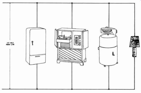
------------ As illustrated graphically, the wiring system in a home is
arranged so that the various facilities operate in parallel. Thus each is independent
of the others.
What is the polarity of the voltage across R1 and R2 together? The answer is in what we've al ready said about R, and Ro separately. Using the "-" side of R, as the reference, the voltage across R, is positive. The "-" to " + " indicates the direction of the current. Since the current through Ro is in the same direction, the current is in the same direction from the " -" of R, to the " + " of R2.
The current direction could have been indicated originally with just the "-" of R, and the "+" of R2. Now the voltage across both R, and R2, with the "-" of R, as the reference, is positive. Using the "+" of R, as the reference point, the voltage across R1 and R2 is negative. In brief, it is the reference point selected that determines the polarity of the voltage.
Note that the battery " + " side is connected directly to the "+" side of R2. For the same reason, since the wire symbol does not indicate resistance, the "-" side of the battery is connected directly to the "-" side of R1 . The polarity of the battery voltage is the same as the polarity of the voltage across both R1 and R2. In fact, the battery voltage E is the sum of the voltages across R1 and R2.
In Figure 4, the current passes through R2 from the "-" side of R2 to the "" side, through the wire, through E, through the wire to R, from "-" to the "+" side of R1 . Since the direction of the current is determined by the battery polarity, it doesn't matter at which point in the circuit the description of the complete path is started. There is the same current everywhere in the circuit.
The current entering the resistor is the same amount leaving the resistor.
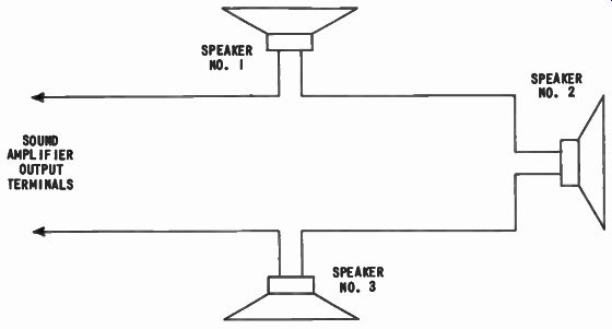
----------- For some applications, speakers are connected of the sound installation
to provide in series across the output terminals adequate sound coverage.
A series circuit can be made up of any number of cells, batteries, and resistors. To be IN SERIES means that the SAME CURRENT must pass through each part since there is only one path. Therefore, in Figure 4, R, and R2 are in series.
Series circuits have three important features:
1. There is only one possible current path.
2. The current is the same at each point in the circuit.
3. Only part of the applied voltage is across each resistor.
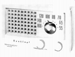
----- A popular type of radio receiver. In small units such as these, the
various components must be arranged carefully to permit the necessary parallel
and series connections. Courtesy Sentinel Radio Corp.
A PARALLEL WATER SYSTEM
The series circuit of Figures 2, 3, and 4 are not the only way in which two or more resistors can be connected. Another method is called a parallel circuit. To illustrate the action of this electric circuit, a parallel water system is pictured in Figure 5. A pump and two narrowed pipes or tubes are connected together, but this time the tubes are not in series with each other.
Let us assume the system is completely filled with water, the pump is operating and water is flowing through the entire system, and that the connecting pipe offers little or no friction to the flow of water.
All the water is flowing from the pump through the outlet pipe A in the direction of the arrow.
The length of the outlet pipe is from the pump to the Junction B leading to Tube #1 and Tube #2.
Upon reaching this junction, the water divides, some of it goes through a pipe to Tube #1 and the rest goes through the pipe to #2. The water flowing from these Tubes combines at Junction C, of intake Pipe D and all the water returns to the pump through Pipe D. The same amount of water leaving the pump by Pipe A re turns through Pipe D. Assuming the pipes have no friction, the entire pressure of the pump is across each tube but only part of the total water flow passes through each.
The important features of this parallel water system are: (1) there is more than one possible path for the water, (2) only part of the total water passes through each tube although the same amount of water returns to the pump that leaves, (3) the entire pressure of the pump is applied across the tube in each separate water path.
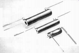
---- Wire wound resistors covered with a ceramic type insulation material.
Courtesy Ohmite Mfg. Co.
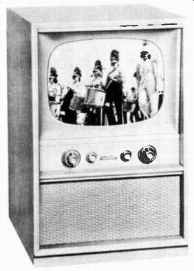
------------- Electronic equipment such as this television receiver contains
a large number of components, many of which form series circuits. Courtesy
Hallicrafters.
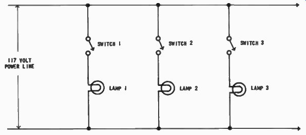
--------- Electric lamps form separate branches of a parallel circuit in
house wiring. In each branch a switch permits the associated lamp to be turned
on or off independently of the others.
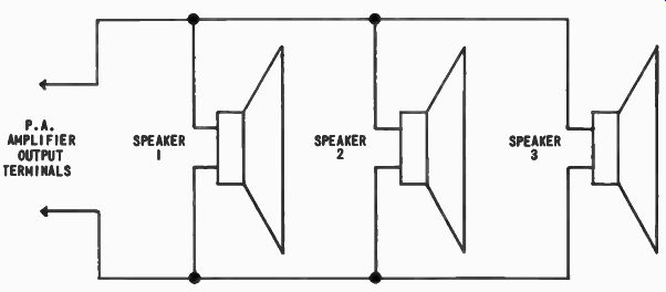
----------- In many sound system installations such as a public address
(P.A.) system, often several loudspeakers are connected in parallel to provide
adequate sound distribution.
A PARALLEL CIRCUIT
Figure 6 is a photograph of a basic parallel electric circuit. A battery takes the place of the pump and two resistors serve the same purpose as the Tubes of Figure 5. The connecting wire replaces the connecting pipes.
Figure 7 is a pictorial diagram of the circuit in Figure 6. Again the parts are drawn in outline just as for the series circuit. E is the battery, 11, represents the inside resistor, and R2 represents the outside resistor shown in the photograph of Figure J. Soldered joints of Figure 6 are represented by twisted lines in Figure 7.
Figure 8 is the schematic dia gram of the circuit in Figure 6.
The two lines joined by a dot indicates that the wires are connected together. Physically, the schematic diagram of Figure 8 does not tell where the connection is made as in a wiring diagram, but only that there is one. When the dot is omitted and the wires cross each other, no connection is indicated. These are the practices in all the lessons. In fact, all symbols used in our texts are those adopted by the Institute of Radio Engineers (IRE) and the American Standards Association (ASA).
Battery voltage E causes the total current to leave the negative terminal through wire A to
the junction of the wires leading to R1 and Ro. At this point, the current divides into two parts, I1 and I2, but the battery voltage E across the circuit remains the same. Current I1 passes through R1 while current I2 passes through R2. Having passed through these resistors, I1 and I2 unite at the junction of the two connecting wires to become then the total current returns to the positive terminal of E through Wire D. Thus, the current leaving and entering the battery is exactly the same as the total of I1 and I2 or I T. All parallel circuits like Figure 8 have more than one current path.
Again, the minus "-" and " + " signs are drawn near each of the resistors to indicate the direction of current through them. Also, they indicate the polarity of the voltage across each resistor.
In the circuit of Figure 8, the battery voltage E is applied across resistor RI, and also across R2.
That is, the "-" side of the battery is connected directly to "-" side of resistors R1 and R.2 and the "+" side of the battery is connected directly to the "+" side of resistors R, and R. Since there is no appreciable decrease of voltage due to the connecting wires, THE FULL BATTERY VOLTAGE E IS ACROSS R1 AND ACROSS R2.
In a parallel circuit, the important features are:
(1) There is more than one current path.
(2) The total current is the sum of the currents through each of the branches.
(3) The total applied voltage is across each branch.
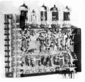
----------------- Inside search wiring view of one section of a nuclear
re instrument. Notice the short, direct that makes circuit tracing a relatively
easy job. Courtesy Tracerlab Inc.
There are two main differences between a parallel and a series circuit:
These are:
(1) In a parallel circuit, the current divides into separate paths and the total current is the sum of the currents in each path.
In a series circuit, there is only one path and so the current is the same throughout the entire circuit.
(2) In a parallel circuit, the applied voltage is across each resistor. In a series circuit, only part of the applied voltage is across each of the resistors in series.
TRACING CIRCUITS
In troubleshooting a circuit, it may be necessary to draw a schematic and a pictorial or wiring diagram of the current paths. A wiring diagram shows the exact physical location of the circuit parts and wires. Sometimes it is valuable to draw the wiring dia gram first and then to draw the schematic from it. Then the wiring diagram is used to locate the trouble indicated by your knowledge of the circuit operation obtained with the aid of the schematic.
Suppose a schematic was drawn of a circuit which appeared as in Figure 4. We can redraw it so that the battery E is shown on the right and the resistors are shown on the left. However, in a redrawn schematic, the same connecting points must be observed, otherwise the two circuits no longer are electrically identical. The schematic diagram shows only the electric connections; it does not show the mechanical layout of the parts.
BUILDING CIRCUITS
Quite often the reverse procedure is desired. Figure 8 may be the schematic of a practical circuit. From it Figure 7 is drawn to show the actual layout for the circuit. In the drawing, the cell and the two resistors R1 and R2 may even be drawn to the same size as the physical dimensions and the wires of Figure 7 may show the actual length. Then by placing the parts in the positions drawn, a neat circuit can be wired for use.
A good practice to observe in building circuits is to wire components following the direction of the current. Start from the ",-" of the voltage source and wire the components in position until the "+" of the voltage source is reached.
CURRENT IN ELECTRIC CIRCUITS
In an electric circuit, the current passes from the negative terminal of the battery through the resistors and returns to the positive terminal of the battery. This is true in all electric circuits: series or parallel. What determines the current in these circuits is the applied voltage and the resistance of the circuit. Once these factors are known the total current can be determined.
In fact, the current, voltage, and resistance are related to each other. This relationship is described in the next lesson by using the basic circuits just explained.
IMPORTANT DEFINITIONS
PARALLEL CIRCUIT-[PAR uh lei SER kut]--a circuit with more than one current path.
SERIES CIRCUIT-[SEE reez SER kut]-a circuit with two or more parts having only one current path.
SUBSCRIPT NOTATION--numbers shown at lower right of a symbol, as R1.
WORK DIAGRAMS
To do your work properly as an electronic technician, you will have to be able to follow electron circuit diagrams. Also, it will be necessary often to follow the wiring and circuit connections in the electron equipment itself. Occasionally, you will need to sketch your own diagram of some piece of equipment for which no data is avail able. In fact, as you proceed with your lessons, you will learn that all electron components are represented in diagrams by means of symbols on the order of those illustrated in this lesson. To make a circuit diagram, a technician draws these symbols in any convenient location on a sheet of paper, and then connects their terminals with straight lines. The straight lines represent the wires which connect the actual components in the electron device.
For example, below are schematic symbols of a line cord plug and a switch. Suppose we desire to sketch a diagram of a line cord containing a switch of this type. First, we draw the two symbols, thus: PLUG SWITCH
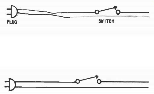
------
Then, we add lines to represent the wires of the line cord connecting the plug to the switch.
This and following lessons contain problems in circuit study which we call work diagrams. Their purpose is to provide you with practice in following circuit wiring and in drawing diagrams. Also, for practice in reading diagrams, some of the problems ask you to complete pictorial sketches of various equipment by drawing in the connections indicated in circuit diagrams. To provide a variety of work diagrams, some problems may be concerned with electron equipment which you have not yet studied in the lessons. However, you should be able to follow the connecting wires and sketch the diagrams, regardless, just as you are able to tune in a program on a radio or television receiver whether or not you know how the receiver functions. As you advance in your studies, the operation of all of these units are explained in detail.
In each lesson, when you have completed the work diagrams, check with the solutions which are given on the back of one of the foldout sheets.
1. Draw pencil lines connecting the symbols to form the circuit diagram of the units in the pictorial sketch.
RDE PLUG LAMP
2. This circuit is like that of problem 1, but has a switch in one wire of the line cord. Draw the circuit diagram, using the symbols given below.
* SWITCH
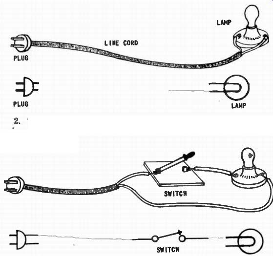
--------
3. Sometimes, a switch is mounted in a metal box which serves as a protection. In this example, the wires leave the switchbox to supply current to some electric device which is not included in the drawing. Since the box is not actually part of the electric circuit (does not carry the current), it is not included in the circuit diagram.
Draw the diagram.
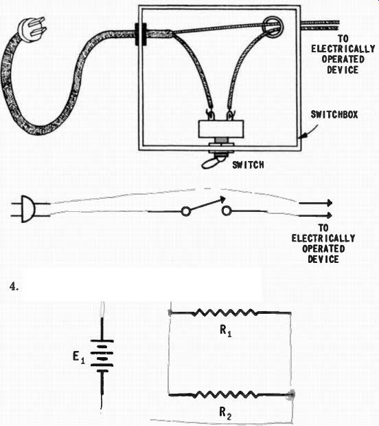
---
4. Complete the following parallel circuit.
When you have completed these diagrams, check your work with the solutions given on the back of the foldout sheet.
STUDENT NOTES
--------------38 / 39
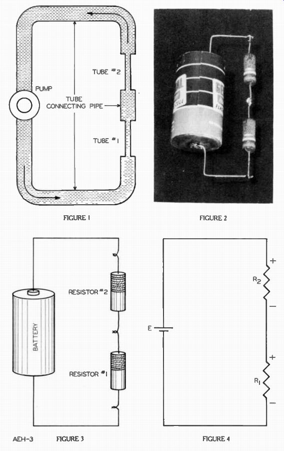
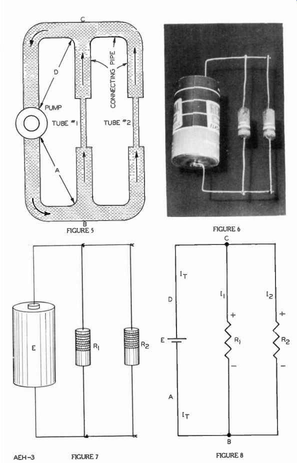
FIGURE 1-4--FIGURE 8
FROM OUR Director’s NOTEBOOK
IMPORTANCE OF A GOOD FOUNDATION
While we were making a trip to Milwaukee recently, the train stopped on one side of a bridge on the Sixth Street Viaduct, and we had to get oft, walk across the bridge, and board another train waiting on the other side.
Upon inquiring why, we were told that the original foundations for the bridge structure were not strong enough for the bridge to carry the new heavier trains. Consequently, service had to be interrupted now while they were being reinforced.
It is such Interruptions in your radio progress that we want to avoid, by stressing all fundamentals and laying a good foundation knowledge that will enable you readily to adopt yourself to new innovations.
Alter all, there are number of basic facts and principles that underlie all electrical and radio operations, and any new circuit features, etc., ore merely different adaptations of these some fundamentals. Therefore, don't delay your advancement later on by passing lightly over any of these early lessons. Master each one thoroughly today, and you'll be prepared for the new things of tomorrow.
Yours for success,
DIRECTOR