AMAZON multi-meters discounts AMAZON oscilloscope discounts
Lesson AEFI-4A
ELECTRONS RELAY MESSAGES
With no idea of the vast and expanding field of electronics, the general pubic regards broadcast radio and television as the principal applications. Actually, these ser vices employ only 1 out of every 20 of the licensed transmitters in use. Most of the electron equipment of this type is used for relay, radiotelephone, facsimile, remote control, telemetering, navigational aids, and experimental work.
Furthermore, all the transmitters in use employ less than one-fifth of the total amount of radio frequency power generated for various purposes, and all the radio frequency power applications form only a part of the gigantic field of electronics.
Communication, transportation, medicine, re search, industry, commerce, and entertainment all find electronics vital to their success.
VOLTAGE-CURRENT-RESISTANCE
Contents
Standard Units
Voltage and Current
Voltage and Resistance
Resistance and Current
OHM'S LAW in Series Circuits
OHM'S LAW in Parallel Circuits
Rules for Any Electric Circuit
If yesterday was a dismal failure, then turn those failings into successes today. Josh Billings once said, "It ain't no disgrace to make a mistake. The disgrace comes in making the same mistake twice".
VOLTAGE-CURRENT-RESISTANCE
The 20th century is filled with new inventions and advances in every field. Radio, television, and all of electronics have certainly contributed a huge part of these advances and new inventions. This outstanding success is primarily the result of measurement. House wives measure with spoons and cups to bake a good cake, a ma chine operator measures with calipers and micrometer, and even your doctor checks your blood pressure by means of a calibrated mercury column.
In electronics, measurements reveal just how the electric circuit is behaving. With the circuit operating properly one set of readings is obtained; with a trouble or fault in the circuit, different readings appear.
For the same reason that a ruler is marked off in a standard inch, foot, or yard, electric meters must use standard units. E is measured in volts, I is measured in amperes, and R in ohms.
An ampere indicates the number of electrons that flow past a particular point in a conductor in a given time.
STANDARD UNITS
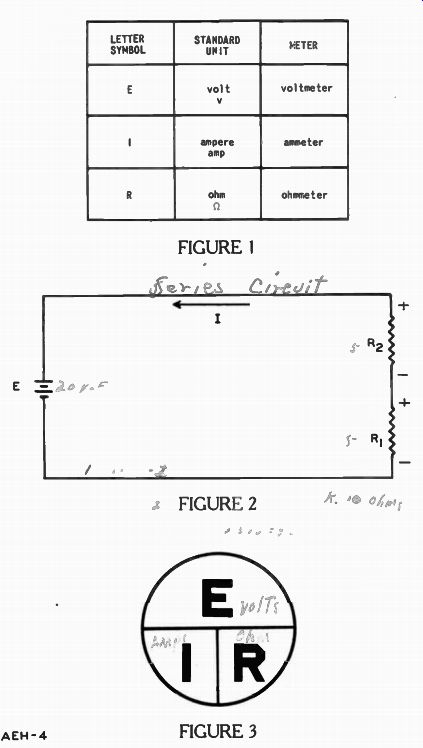
The chart in Figure 1 illustrates the letter symbol, the standard unit and its abbreviation, and the meter used to measure this unit. Read each row across for the complete story. That is, the electric pressure E is measured in volts (v) by a voltmeter. The rate of electron flow or current I is measured in amperes (amp.)
By an ammeter, and the resistance R given to this flow is read in ohms (omega) on an ohmmeter. (omega) is the Greek letter omega used by many people to represent ohms.
With standard units of a VOLT, AMPERE, and OHM, we can make comparisons in an electric circuit.
You may suspect that all these standard units are somehow related. They are, and the three combined tell a story which leads to a better understanding of all electric circuits. But, first let's compare two at a time.
VOLTAGE AND CURRENT
The series circuit described in a previous lesson is shown here in Figure 2. IN ANY SERIES CIRCUIT, THE TOTAL RESISTANCE IS EQUAL TO THE SUM OF THE INDIVIDUAL RESISTANCES. Thus, if R1 and R2 are each I ohm, the total resistance of this circuit is 4 + = 1 ohm. A battery voltage of 10 volts will produce a current of 10 amperes in the circuit.
In the water system described in the last lesson, when the pump has a pressure of 10 units, it pumps 10 gallons per minute.
When the pressure is increased to 20, it can pump 20 gallons of water per minute through the same pipes. Twice as much water is pumped because the pressure has doubled.
In much the same manner, in the electric circuit of Figure 2 if the 10 volts is increased to 20 volts, the current doubles so long as the resistance remains the same. The voltage is increased by either using two ten volt batteries in series which gives ten plus ten or twenty volts, or replacing the two with a single 20 y battery. With the 1 ohm resistance, the current I increases to 30 amperes when the voltage is increased to 30 v. In fact, increasing the voltage in the circuit, while the resistance remains constant, always increases the current.
Although the voltage in this electric circuit came from a battery any other source of voltage could have been used. The important thing is: for a constant resistance increasing the voltage increases the current by the same amount.

------------- A multi-service combination which provides a choice of television
reception. AM or FM radio reception, or record playing. Courtesy Zenith Radio
Corporation
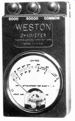
----------- Ohmmeters operate by using Ohm's Law. By placing a fixed voltage
across the unit and measuring the current, this meter can indicate the resistance
of the unit. Courtesy Weston Electrical Instrument Corp.
When one quantity is increased by a specific number of times and another quantity increases by the same amount, the two quantities are directly proportional to each other. When the two quantities decrease together by the same number of times, they also are directly proportional.
The following example shows two quantities NOT directly proportional. Suppose the power sup plied by the motor is 20 horse power when the car speed was 25 miles an hour. If raising the power output to 60 horsepower only increases the speed to 50 miles an hour, then triple power only doubles the speed. In this situation, the quantities do NOT vary in direct proportion.
For two quantities to be directly proportional, they MUST both increase or decrease the SAME number of times from their previous value. When the current increases 1 1/2 times, so must the voltage, when the resistance re mains unchanged.
We can state for the above situations: IN AN ELECTRIC CIRCUIT, THE CURRENT I IS DIRECTLY PRO PORTIONAL TO THE VOLTAGE E WHEN THE RESISTANCE IS HELD CONSTANT.
Radio, television, and other electronic servicemen frequently take advantage of this relation ship to determine whether a circuit has sufficient electron flow.
Although a "current meter" can be used for this purpose, as you will find out in the next lesson, it must be connected in series with the other circuit components. Frequently, this requires disconnecting a circuit wire to insert the meter. It is much quicker to use a voltmeter across one of the components. Since the voltage across the component increases with the current through it, the technician can quickly determine whether there is a current, and if it is near normal, without taking the time and effort to disconnect wires.
VOLTAGE AND RESISTANCE
We can treat the voltage and resistance relationship the same way we described for current and voltage. Both kinds of changes sometimes occur even in the same circuit. At one time, the voltage and current change and the resistance remains the same, while at a later moment only the voltage and resistance change.
We can learn how the relation ship between voltage and resistance works when the current is held constant, by starting with the electric circuit of Figure 2 when E was 10 volts applied across both R1 and Ro, the total of R1 and Ro was 1 ohm, and the current was 10 amperes.
Now suppose the voltage is doubled to 20 volts. To keep the current at 10 amperes, the resistance must double, so the total resistance of R1 and R2 is 2 ohms.
Again when the battery voltage is increased to a 30 volts, the total resistance must increase to 3 ohms to hold the current constant.
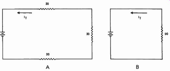
---------- So far as circuit current is concerned, the three 30-ohm resistors
in series offer the same opposition in circuit A as offered by the single 90-ohm
resistor in circuit B.
WITH A CONSTANT CURRENT, THE VOLTAGE E IS DIRECTLY PROPORTIONAL TO THE RESISTANCE R. Increasing or decreasing the voltage a certain number of times means that the resistance must be increased or decreased by the same number of times to keep the same current.
RESISTANCE AND CURRENT
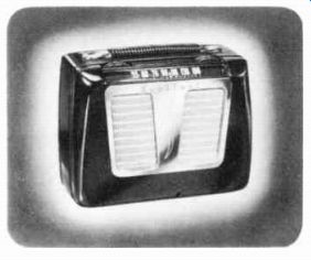
--------------- Several series circuits form parts of the complete circuit
of on electron instrument such as this portable radio receiver. Courtesy Sentinal
Radio Corp.
We have considered two ways in which an electric circuit may change. As you may have guessed there is still a third way: the resistance and current may change at the same time the voltage applied across all the parts remains constant.
Both voltage and resistance, and voltage and current are directly proportional to each other.
However, the same relationship does not hold true for current and resistance. In fact, just the opposite is true; as I increases R decreases for any fixed voltage E. In the electric circuit of Figure 2, if the battery voltage E is 20 volts and the current is 1 ampere, the total resistance of R1 and R, is 20 ohms. Now by keeping the voltage E constant but reducing the total resistance to 10 ohms, the current meets less opposition and so it increases to 2 amperes. Halving the resistance doubles the current for the same battery voltage. Suppose the total resistance of R1 and R2 is decreased to 1 ohm. With the same battery voltage E, the current becomes 20 amperes. That is, when the total resistance is decreased 20 times, the current is increased 20 times.
When the voltage is held constant in an electric circuit, the current I increases the same number of times that the resistance decreases. This relationship is expressed by saying: The current I and resistance \ R are inversely proportional to each other.
In electronics, there are a large number of circuits in which the voltage remains constant while the other two vary. A very good example is the "ohmmeter" described in your meter lesson and which you build and use in your laboratory work. Frequently it is necessary for the laboratory technician to measure the resistance of a component to see if it is defective or not. Possibly the simplest way is to apply a fixed voltage across the part in question and determine the current it draws by means of a current meter. The more current drawn, the lower the resistance.
In fact this method is so useful that a current meter, voltage source, and other necessary wiring are enclosed in a case and called an ohmmeter. However, instead of showing the current, the meter scale is calibrated to indicate the resistance that permits this current.
OHM'S LAW IN SERIES CIRCUITS
You'll notice that E, I, or R was held constant in each one of the three relationships described.
This is done with electric circuits in practical situations. Anyone can discover these three relation ships for himself if he so desires by wiring these circuits and measuring the values. These are basic and fundamental relationships which hold true in all electric circuits, whether the voltage is dc or ac.
However, all three of these can be expressed in terms of one over all relationship. Therefore, instead of remembering three separate rules you need only to re member one. Everyone who constructs, installs, maintains and services, or modifies equipment uses this one relationship. It is called Ohm's Law and stated in words is:
IN AN ELECTRIC CIRCUIT, THE CURRENT IS DIRECTLY PROPORTIONAL TO THE VOLTAGE AND INVERSELY PROPORTIONAL TO THE RESISTANCE. All are measured in standard units of amperes, volts, and ohms.
Figure 3 is an aid to finding one of the three, the E, I, or R in an electric circuit when the other two are given. It puts all three letter symbols in a short, easy to use form.
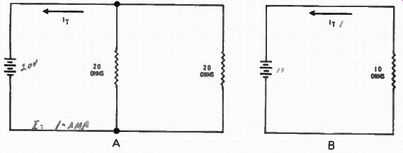
-------------- So far as the total circuit current I_T is concerned, two
20 ohm resistors in parallel offer the same opposition in circuit A as the
one 10 ohm resistor in circuit B.
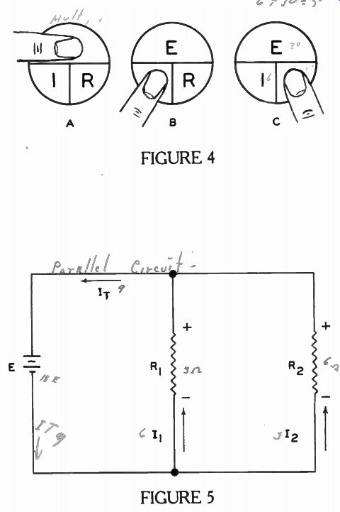
How this Figure can be used is illustrated in Figure 4. By placing your finger on the symbol for the value that you wish to determine there are two left exposed. If both symbols are below the horizontal line as shown in Figure 4A, then one must be multiplied by the other, but when one is above as shown in Figures 4B and 4C, the top value is divided by the one left exposed below the line. For Figure 4A, Ohm's Law can be written as:
Volts is equal to amperes times ohms.
For Figure 4B, the relationship can be written: Amperes is equal to volts divided by ohms.
For Figure 4C, the relationship can be written: Ohms is equal to volts divided by amperes.
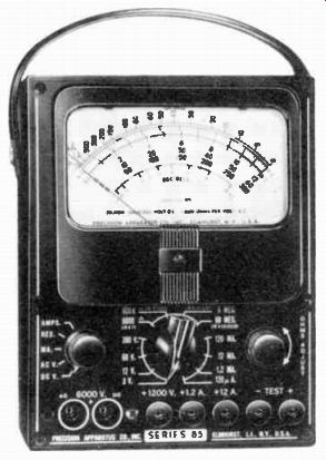
---------- An instrument of this type is used when it is desired to measure
the voltage, current, or resistance of a circuit. Courtesy Precision Apparatus
Co., Inc.
Note in all three of these statements the value being sought appears as the first word.
How easy and practical this device is can be illustrated by a sample problem or so. For example, when it is known that the current is 5 amperes through a resistor of 5 ohms, then the voltage across the resistor can be determined. After covering up E since it is the value that is un known as shown in Figure 4A, substitute 5 amperes for the I and 5 ohms for R. Since both symbols are below the line, multiply these two values together, 5 times 5 = 25. Therefore, E is 25 volts.
The three relationships between I and R, E and I, and E and R described for Figure 2 are just special cases of this Ohm's Law.
For our first case we began with 20 ohms and 1 ampere at 20 volts. Then we changed to 10 ohms and 2 amperes, and finally to 20 amperes and 1 ohm. Multiply the 20 by 1, the 10 by 2, or the 1 by 20, and the result in each case is 20 volts. That is, the voltage was held constant at 20. Let's see how Ohm's Law holds in the relationships between E and I. The first case described was 10 volts and 10 amperes; second was 20 volts and 20 amperes; and the third, was 30 volts and 30 amperes. Now recall that the resistance was held constant for all three. Using Figure 4C: 10 divided by 10 = 1, 20 divided by 20 -= 1, and 30 divided by 30 = 1. One ohm! So, the resistance used in this circuit for the E and I relationship remained constant at one ohm.
For the E and R relationship described, the current was held constant for all the electric circuits. Let's check it by using Figure 4B. The values for E and R were: 10 volts and 1 ohm, 20 volts and 2 ohms, and 30 volts and 3 ohms. Since 10 divided by 1, 20 divided by 2, and 30 divided by 3, all equal 10, the current remained constant at 10 amperes.
Notice in Figures 4A, 4B, and 4C that two values remain uncovered. This means that two values must be known before the third one can be determined. It is impossible to determine one unless both of the others are known.
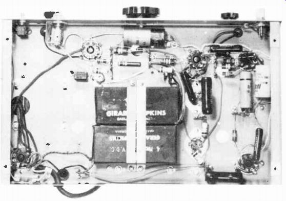
-------------52 Under-chassis view of a piece of electron equipment, showing
various types of components, some of which form branch parts of parallel circuits.
Courtesy Hewlett-Packard Co.
To demonstrate this law, let's use the series circuit of Figure 2 again, by letting R1 be 2 ohm, R4 be 7 ohm, and the battery 27 v. To find the current, use the total resistance, 2 ohm plus 7 ohm which is 9 ohm, and the 27 v. Substituting both values as in Figure 4B, nine ohms divided into 27 v is 3 amperes.
Since we know the current through each resistor is 3 amperes and its resistance, we can find each resistor voltage using Figure 4A. For the voltage across R1 , 2 ohm and 3 amp. gives 6 v. Likewise for R2, 7 ohm and 3 amp results in 21 v. As a check, the total of both voltages should equal 27 v applied across both resistors. Adding 21 v to 6 v gives 27 v, and so our results are correct.
OHM'S LAW IN PARALLEL CIRCUITS
Of the two basic types of circuits, parallel is the more common in ordinary house wiring and every plug-in appliance is connected in parallel into this wiring. Each time you turn on a light, radio, television, etc., you complete one more parallel branch.
At times, there are many appliances on at once. Turning on just one more stops the operation of each, because you "blow" a fuse.
One such fuse is ordinarily rated about 20 amperes and the last appliance uses enough additional current to exceed this limit. To protect both the electric circuit and your house, the material in side the protected container of the fuse melts and safely breaks the circuit. For this reason copper pennies or other such substitutes should never be used. Only fuses of the correct rating are proper replacements.
Knowing the current used by each gadget and totaling it, you will find how many appliances can be on at the same time with out blowing a fuse.
We can go further with parallel circuits by applying Ohm's Law, just as we did for series circuits since, it applies to all circuits equally well. For example, in the parallel circuit of Figure 5, E is an 18v battery connected across two resistors in parallel. R1 is 3 ohms and R. is 6 ohms. In the previous lesson it was stated that voltages across all the branches are the same as the applied voltage. Also, the current paths were described and it was found that the total circuit current I_T is the sum of the branch currents I_1 and I_2. R1 and R2 are marked by + and - to remind you of the direction of the current through the resistors. Now the question is: What are I1 , I2 and I_T? We know the voltage across R1, and that the resistance of R1 is 3 ohms. Only I1 is the unknown.
Substitute 18 v and 3 ohms in Figure 3 by covering up the I as shown in Figure 4B, 18 volts di vided by 3 ohms is 6 amperes.
This is the current through R1, and so it is only PART of the total current I_T. The current 12 can be found the same way. Substitute 18 volts and 6 ohms into Figure 4B; 18 volts divided by 6 ohms is 3 amperes.
The total current I_T is the sum of 3 amperes and 6 amperes or 9 amperes. Thus, there is 9 amperes from the negative terminal of the battery and 9 amperes back into the positive terminal of the battery.
Since in a parallel circuit the battery voltage across each branch is the same, there is 6 amperes or twice the current through the 3 ohm resistor as through the 6 ohm resistor.
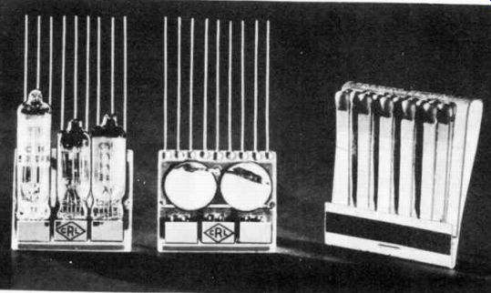
--------------- A new technique of circuit design and construction permits
the assembly of extremely small electron equipment such as this three tube
hearing aid amplifier. Courtesy Contralab Division of Globe Union, Inc.
Knowing the TOTAL CURRENT and the applied voltage in this parallel circuit, the total resistance of a parallel circuit can be found by using Ohm's Law. Substitute 18v and 9 amperes into Figure 4C. Divide the 18 volts by 9 amperes, and the answer is 2 ohms. This means that to get the same total circuit current I_T, a three and a six ohm resistor in parallel can be replaced by a single resistor of 2 ohms. Note that the total resistance of a parallel circuit is NOT the sum of 3 and 6; it is LESS than either. THE TOTAL RESISTANCE IS ALWAYS LESS THAN THE RESISTANCE OF THE LOWEST BRANCH IN PARALLEL CIRCUITS. Let's repeat the procedure to find the currents and total resistance in a parallel circuit before taking another illustration. Both resistances were known along with the applied voltage. Using Ohm's Law as shown in Figure 4B, the current I1 was found to be 6 amperes. Using Ohm's Law in Figure 4B, 12 was found to be 3 amperes.
In a parallel circuit, the total current I, is the sum of the branch currents. Thus I_T is equal to 3 amperes plus 6 amperes or 9 amperes. Using Ohm's Law, this time in Figure 4C, with the total current and voltage, the total resistance was found to be 2 ohms.
For another example, let E in Figure 5 be 20 volts, resistor R1 is five ohms, and current I_2 is 2 amperes. Suppose current I1 and the resistance R2 must be known.
What do we do to find them? To find I1 first, we must know the voltage across R1 and the resistance of R1 to use Ohm's Law.
Both are given, R1 is 5 ohms and E1 is 20 volts. Substituting in Figure 3 for E and R, as shown by Figure 4B; I1 is 20 volts divided by 5 ohms, or 4 amperes.
Using Ohm's Law to find R2, since the voltage and current I2 are known, by substituting 20 for E and 2 for I in Figure 4C, 20 di vided by 2 is 10 ohms. Thus, by using Ohm's Law twice, R2 and I, are determined. In each case, two things were known before the third could be found.
Since the total current is the sum of the branch currents I1 and I2, I_T is 4 amps plus 2 amps or 6 amps. This 6 amperes leaves the negative terminal of the battery and at the junction of R1 and R2 divides, 4 amps goes through R1 and the other 2 amps pass through R.. I1 and I_2 rejoin on the "+" side of junction of R1 and R2, and the total 6 amps enters the "+" side of the 20 v battery.
Since we know both the total current is 6 amperes and the battery has 20 volts we can find the total resistance by using Ohm's Law. Substitute 20 for E and 6 for I in Figure 4C; 20 divided by 6 is 3.33 ohms.
The total resistance in a parallel circuit is always less than the resistance of each branch.
This is true because the total current is larger than any branch current, and using Ohm's Law the same applied voltage divided by the larger current gives a smaller resistance.
Thus in parallel circuits:
(1) The applied voltage is across each branch.
(2) Apply Ohm's Law to each branch or part of the circuit to determine the current or resistance when the voltage is known.
(3) The total current is the sum of all the branch currents.
(4) The total resistance is found by using in Ohm's Law the total current and the applied voltage.
(5) The total resistance is al ways less than the smallest branch resistance.
RULES FOR ANY ELECTRIC CIRCUIT
Ohm's Law can be applied in any electric circuit. However, to avoid confusion, don't rush into the problem. Follow a procedure, such as:
(1) See that the circuit is a complete path, otherwise current will not pass through the parts.
(2) Try to trace the current path through all the components at the same time labeling "-" and "+" across each of the components.
(3) See which things are known and which are unknown.
(4) Decide which of the three forms of Ohm's Law will be used in that portion of the series or parallel circuits.
(5) Apply Ohm's Law to each unknown, taking one unknown at a time.
(6) Make sure the two values selected when applying Ohm's Law are for the same portion of the circuit.
(7) As a check, be sure that the total of the voltages across the parts in a series circuit does not exceed the applied voltage.
(8) In a parallel circuit: (a) The voltage across each branch is the same. (b) The total current is the sum of the branch currents.
Actual voltages, currents, and resistances of the circuit combined with Ohm's Law tell how a circuit operates. In your laboratory projects, you will find that these values are not seen or counted by looking at the circuit and so electric meters must be used to measure them. Therefore, every electronic technician should know how to use meters correctly. These methods are described in the next lesson.
--------------------
IMPORTANT DEFINITIONS
DIRECTLY PROPORTIONAL--Two quantities increase or decrease the same number of times their previous value.
INVERSELY PROPORTIONAL--With two quantities, one increases while the second decreases the same number of times.
---------------------
WORK DIAGRAMS
When you have completed these diagrams, check your work with the solutions given on the back of the foldout sheet.
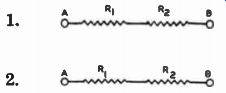
1. The sketch below shows two fixed resistors connected to form a circuit between terminals A and B. Draw the circuit diagram, using the proper schematic symbols for the resistors. Remember, a schematic diagram is arranged to show the electric connections in the simplest manner possible, and does not need to correspond to the physical placement of the parts. Label the resistors as R1 and R2, to show that R1 connects to terminal A, and R2 to terminal B. r - n
2. Draw the circuit diagram, substituting schematic symbols for the resistors. Arrange your diagram so there are few if any crossed lines, and label the symbols to correspond with the sketch.
------------ FIGURE 1 - 3
WORK DIAGRAM SOLUTIONS
Your drawings may not be arranged exactly like the ones given below, but they should contain the same electric connections.
1.
2.
--------
Problems 1 and 2 were made alike, electrically, to show that there are more ways than one, usually, to make the physical connections of any given electric circuit.
------------- FIGURE 4; FIGURE 5.