AMAZON multi-meters discounts AMAZON oscilloscope discounts
Lesson AEH-6A
ELECTRONS GAUGE MATERIALS
Formerly a slow, tedious task requiring considerable skill and subject to errors, sorting ball bearings as to size now consists of simply pouring a batch of the bearings into a hopper and letting an electronic gauge do the actual sorting. Quickly, each bearing is tested and then dropped into the proper one of several bins. In each bin, all bearings are within of the same size. Using this 100,000 modern method, one laborer can do the work of 30 skilled operators.
Practically any characteristic of a material such as weight, thickness, color, or hardness, can be measured accurately by electronic devices which form a large proportion of the many types of gauges and other testing equipment used by modern industry.
TWO ELECTRODE TUBES
Contents
Early Electron Tube Developments
Electron Emission
Emitters
Plates
The Diode
Construction
Operation
Basic Rectifier Circuit
An Electronic Power Supply
Weakness does not prevent success if only the body is weak. The trouble in the average person is not lack of ability, intelligence, or health. It is lack of courage that comes from enthusiasm.
-Arthur Brisbane
TWO ELECTRODE TUBES
Much of the progress in the 20th century is due primarily to electronics, and probably the one single component that has made electronics most possible is the electron tube. Mechanically, it is nothing more than a few parts enclosed in a glass or metal container, yet it possesses some very important features.
Used in a radio, electron tubes bring far away voices and music into your home. Television, again with the aid of the electron tube, brings into your living room the scene with the sounds as they happen. Miles away a valve is closed almost instantaneously because of electron tube action at a central control station.
However, most electron tubes require d-e for their operation, and as you probably know, most utility companies supply a-c.
Thus, some means is required within electronic equipment to change the a-c into d-c. The con version itself usually is performed in a circuit by a two electrode tube.
EARLY ELECTRON TUBE DEVELOPMENTS
In 1883, while developing the electric lamp, Thomas Edison noticed that the inside of the glass bulb became blackened and this caused a reduction in light after the lamp was in use for a short time. In the process of investigating this fault, Edison mounted a metal plate inside the lamp bulb and connected it to a milliammeter as shown in Figure 1. He ob served that when the switch made contact with the "+" terminal of the battery, the meter indicated current in the direction shown by the small arrows. On the other hand, when the switch connected with the " -" terminal, there was no meter deflection.
Since he did not attempt to explain or use his discovery, the "Edison Effect" remained nothing more than a scientific curiosity until 1904. Then Dr. J. A. Fleming used a device, like the one shown in Figure 1, in experiments with radio telegraph currents. This first electron tube was known as the "Fleming valve" and, although a simple device, it paved the way for the many other types of electron tubes used today.
ELECTRON EMISSION
In order to deflect the ammeter of Figure 1, a current must pass between the filament and plate in side the lamp bulb to complete the circuit. It was not until the advancement of the "electron theory", several years after the discovery of the Edison effect, that scientists were able to explain satisfactorily this conduction between the filament and plate. Ac cording to present theory, this conduction is due to a flow of electron's which leave the filament of which they are a part and flow to the plate. This escape of the electrons from the filament is called electron emission.
This emission is somewhat like boiling water away into steam.
Heated to a high enough temperature some of the water becomes very active. Just look at the way water bubbles when it gets hot! As the very hot water is pushed to the surface, it is moving so rapidly that it overcomes the force holding it to the surface, and escapes in the form of steam.
As explained in an earlier lesson, when a difference of potential exists between two points, electrons flow toward the most positive potential. Figure 1 shows the plate connected to the " + " of the battery and the filament \ connected to the "-" terminal.
Therefore, a force exists between the plate and the filament, and the negative electrons are attracted toward the positive plate.
When certain metals are heated, electrons are emitted readily from their atoms. However, in leaving, these electrons cause a shortage of negative charges which results in positively charged atoms at the filament. Since unlike charges attract, these positive charges attract most of the negative electrons back into the atoms of the filament.
However, when the heated metal is placed in a vacuum, a number of electrons leave the atoms with sufficient force to overcome this attraction and continue their movement into free space. This type of electron emission is utilized in most electron tubes and is referred to as THERMIONIC EMISSION.
----------- Although the most important single component in electronic
equipment, the electron tube is usually a compact unit. Courtesy General Electric
Co.
A practical method of producing a thermionic emission element is to form a metal into a wire, or filament, and place it in a glass bulb like that used for the ordinary light bulb. The air is pumped out of the bulb to form a high vacuum which not only prevents the filament from combining with the oxygen in the air and thus "burning up", but also improves the electron emission. When connected to a voltage source, the resulting current heats the filament and electrons are emitted from its surface. This emission element of an electron tube is called an "emitter". EMITTERS In the majority of electron tubes, the emitter is either of the directly heated or the indirectly heated type. The "directly heated" type consists of a filament which, when heated, acts as the emitter. Figure 2 shows the mechanical construction of three types of directly heated emitters or filaments which differ in the method of filament support. In each case, the supports connected to the ends of the emitter are conductive and are used to complete an electric circuit from an external voltage source through the base of the tube.
For large electron tubes, directly heated emitters are made of pure tungsten because this metal does not vaporize when heated to a temperature high enough to produce satisfactory emission. However, tungsten re quires a comparatively large current to provide the proper operating temperature.
A more common directly heated emitter, known as the thoriated filament, is made by dissolving a small quantity of thorium oxide and carbon in a tungsten wire.
When heated, the thorium works its way to the surface of the filament where it is deposited in a thin layer. The emission takes place from this layer at temperatures much lower than required for pure tungsten. As the thorium on the surface is exhausted, a new supply "boils out" from the interior of the wire, thus renewing the outer layer and maintaining proper emission.
Another common emitter is the oxide coated type. It consists of a platinum or nickel wire coated with an oxide of barium, strontium, or calcium. These materials readily emit electrons when heated. This type of emitter is widely used in the small sized tubes be cause it operates at temperatures only slightly more than half of that required for the thoriated filament type.
Battery sources of current, called "A" batteries, are used for filament heating in mobile, port able, and other equipment designed to operate independently of local power sources. However, the most common source is ordinary 60 cycle alternating current which is supplied by the utility companies. Not only is it an economical power, but by means of the transformers to be described a couple of lessons from now, the common 110-120 volt 60 cycle sup ply voltage can be reduced to any desired filament voltage.
Within certain limits, the emission of electrons varies with the temperature which in turn varies with the filament current. Although a desirable source, alternating current drops to zero each time it reverses. With the common 60 cycle supply, the changes take place so rapidly that the filament never cools entirely. however, these periodic changes of temperature are sufficient to cause some variation of emission. For sensitive electron circuits, this variation produces a very undesirable operation.
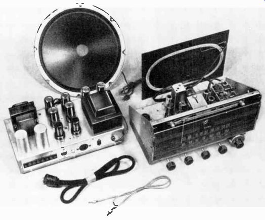
---------- The various components of this radio receiver are mounted on
two chassis. The one on the left contains the power supply and the output circuits
of the receiver, while the other contains the remaining receiver circuits.
Courtesy Espey Mfg. Co., Inc.
Because of these conditions, most modern tubes are constructed so that the filament proper is used only to heat a surrounding element that emits the electrons.
When heated indirectly in this manner, the emitter temperature doesn't follow these rapid filament heat fluctuations but re mains fairly constant. Used in this way, the filament becomes a heater, and the source of electrons is an "indirectly heated" emitter. Called a cathode, this type of emitter is made of metal coated with an oxide just the same as the directly heated types. However, it is in the form of a cylinder which fits snugly around the heater itself consists of a tungsten or tungsten alloy wire which is coated with an insulating material.
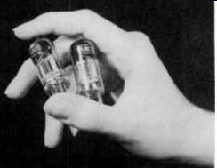
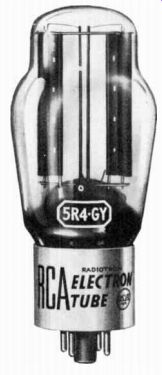
----------- A high vacuum, half-wave rectifier tube commonly employed in
high voltage power supplies. Courtesy RCA the heater.
The constructions of two types of indirectly heated emitters are shown in the cutaway views of Figure 3. In Figure 3A the heater is wound in a double spiral, that is, the wires are twisted about each other. Figure 3B is a folded heater. Different companies hold patents for, or favor one of these two methods.
Usually, individual supports, which are good conductors, are provided for the heaters and the associated cathode. These pass through the base of the tube to the connecting pins below so that the electric circuits of each may be entirely separate.
PLATES
Since the prime purpose of the plate or anode of a tube is to collect the free electrons, usually it is constructed in the form of a cylinder, like those illustrated in Figure 4, and mounted inside the bulb or envelope so as to completely surround the emitter. As a result, all electrons emitted from the cathode are attracted directly to the plate when it is positive with respect to the cathode.
Usually, nickel, iron, molybdenum, tantalum, or various alloys of these metals are used for the plate material. Not only do these metals produce a rigid plate capable of dissipating heat, but they also show very poor electron emission characteristics even when the plate becomes quite hot.
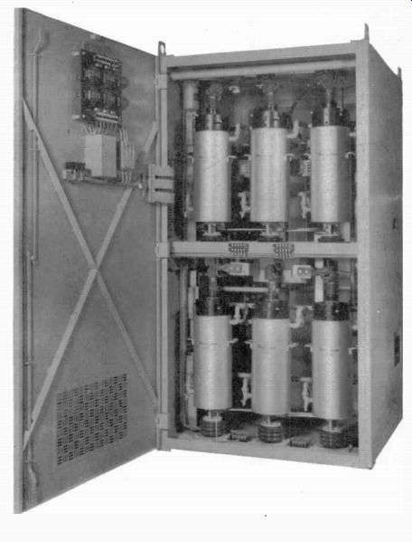
------------ Used in industrial electronics, these cylindrical
THE DIODE An electron tube containing an emitter and a plate or anode is called a diode. The prefix "di" comes from the Greek language meaning two, and "ode" is a con traction of the word electrode.
Thus diode literally means a two electrode tube. However, a diode tube may contain a heater, cathode, and plate because the heater and cathode function as one electrode although they are two separate elements.
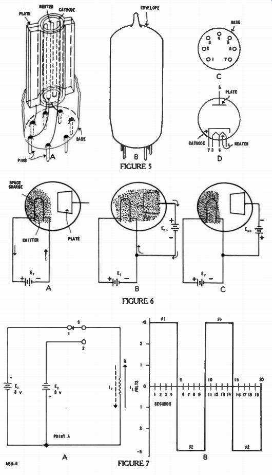
Construction As shown in Figure 5A, a modern diode tube is constructed internally so that the heater is surrounded by the cathode which in turn is surrounded by the plate.
Connections from the external circuit are made to the tube elements by metal pins which extend through the bottom or base.
When assembled With the bulb in place, some tubes of this type have the general appearance of Figure 5B, with a base pin arrangement as pictured in the bottom view of Figure 5C. Notice that the- pins are numbered from 1 to 7 in the clockwise direction starting with the pin after the wide gap. Not only does the gap indicate where the pin numbering starts, but also makes it difficult to insert the tube into a socket in a wrong position.
Figure 5D is the schematic dia gram symbol used to designate a diode tube. The circle represents the shell or "envelope", the inverted "T" indicates the plate, an inverted "V" or "W" designates the filament or heater, and the cathode is represented by an inverted "L". Often adjacent to each element in the symbol, a number is added to indicate which base pin it connects to. Thus, when used in a diagram the symbol indicates the type of tube, the electrodes it contains, their connections to the external circuit, and the numbered base pins.
Operation
The operation of a diode is illustrated in Figure 6. Here, the emitter is of the directly heated type, and is supplied heating current from the battery E1 . E, is the standard symbol for the heater or filament voltage. In Figure 6A, arrows indicate the path of this current, the complete circuit of which is called the "filament circuit". Heated to a high temperature by the battery current, th emitter "boils" electrons off into the surrounding space. After the circuit has been on for a moment, the emitter is left with a shortage of electrons, or a positive charge, which attracts the electrons back, and at any given emitter temperature, the number pulled back is equal to the number emitted.
Therefore, in the area surrounding the emitter, there is a cloud of electrons, some of which are moving away and others of which are moving toward the emitter. This electron cloud is known as the space charge. With no external connection, the plate has no effect on the space charge which builds up to a density determined by the emitter's temperature.
When the plate is connected to a source of voltage, such as battery Ebb in Figure 6B, and the emitter connected to the opposite terminal of the same source, a difference of potential is produced between the emitter and the plate.
With Ebb connected as shown, the plate is made positive with respect to the emitter. Under these conditions, an electric attraction is set up between the two elements. The negative electrons in the space charge are attracted by this positive voltage on the plate.
Collected at the plate, the electrons pass through the external lead to the positive terminal of battery With the plate taking electrons from the space charge, there are fewer electrons avail able to return to the emitter than are being given off. Hence, there is a net loss of electrons by the emitter, and a positive charge begins to build up on it. To replace those lost to the plate, and also prevent the emitter from acquiring a positive charge of any appreciable size, electrons flow to it from the negative terminal of Ebb.
------------ A high vacuum, full-wave rectifier tube of the type employed
in a-c operated power supplies. Courtesy RCA.
Thus, a complete path is provided for electron flow from the emitter to the plate inside the tube, and in the external circuit, from the plate, through Ebb to the emitter. Indicated by the arrows in Figure 6B, this path is called the "plate circuit", and the electron flow is known as the plate current.
The difference of potential between the emitter and plate is called the plate voltage. Usually the emitter (filament or cathode) is employed as the reference point for voltages in electron tubes.
Each element contained in the tube is considered either positive or negative (or zero) with respect to the emitter. In Figure 6B, the plate voltage is said to be positive, because the plate is positive with respect to the emitter.
The number of electrons drawn from the space charge to the plate, and hence the size of the plate current depends upon the plate voltage. As the plate voltage is increased, the plate current increases until a point is reached at which the plate is taking ALL K the electrons given off by the emitter.
Raising the plate voltage above this value does not cause any further increase of plate current at the given emitter temperature.
This maximum is called SATURATION CURRENT, and the plate voltage necessary to produce it is called the SATURATION VOLTAGE. Since the plate current does not increase after the saturation voltage has been reached, this condition is known as PLATE SATURATION. On the other hand, if the plate voltage is held constant in the diode circuit of Figure 6B, and the emitter temperature is raised by increasing E, voltage to produce a larger current in the filament circuit, more electrons are emitted to increase the density of the space charge. With more electrons available, a larger number are attracted to the plate. Thus, the plate current increases even though the plate voltage remains constant.
However, as the emitter temperature is raised, eventually a point is reached at which the repelling force of the negative space charge is so great that it prevents any further increase in emission.
For a given plate voltage, the particular emitter temperature above which the plate current does not increase is called the "saturation temperature". This condition is known as CATHODE SATURATION. If a negative voltage is applied to the plate of a diode, by connecting the battery EN, with the polarity as shown in Figure 6C, then the negative electrons are repelled. Under these conditions, no electron flow occurs in the region between the space charge and plate, and so no current exists in the plate circuit regardless of the plate voltage or emitter temperature.
If the diode plate were capable of emitting electrons, the connections of E, in Figure 6C would result in plate current in the re verse direction of that indicated by the arrows in Figure 6B. however, since the cathode material was selected for its good electron emission ability and the anode material has poor emission characteristics, emission takes place only from the filament or cathode. Therefore, the diode conducts plate current ONLY when the plate is more positive than the emitter as in Figure 6B.
A very good picture of how a diode is used can be had by first looking at a circuit without a diode and then use the same circuit with a diode inserted. In Figure 7A are two batteries, E1 and E2, and each has 3 volts. However, due to the way they are connected, it is possible to produce a current in opposite directions through resistor R. When the switch is in position 1 as shown, the positive end of battery E1 is connected to the upper end of R1 and the negative end is connected to the lower end. So long as S is in position 1, E2 does not make a complete circuit with R since only the lower end is connected to the resistor. Electrons flowing from the negative terminal of E1 flow to the right and up through R, as indicated by the solid arrow, and back through the switch to the positive terminal of E1 to produce current I. For this condition the voltage across R is the same as E,. Using Point A as the reference, this would be a +3 volts across R. By repeating this procedure with switch S moved to position 2, Eo is connected into the circuit instead of E1 . Due to the reverse polarity of E., electrons flow from its negative terminal, through the switch, down through R, and back through point A to the positive terminal. This current is represented by arrow I_2. Now with respect to A, the voltage is -3 volts across R. A picture of what happens to the voltage across R as the switch is moved back and forth is shown in Figure 7B. If we start at Position 1 we have + 3 V on resistor R and this remains until the switch is changed. If the switch was held in position 1 for 5 seconds, a horizontal line at 3 units above the base line indicates that all during these 5 seconds the voltage remained at + 3 volts. At the end of 5 seconds if the switch were flipped to position 2, a vertical line from the +3 down to the -3 below the line would indicate that the voltage across R changed from + 3 to 0 and down to -3 so quickly that no lapse of time could be indicated. Now if the switch was held in this position for another 5 seconds until 10 seconds have gone by, a horizontal line would show a -3 volts on the resistor for every instant of these 5 seconds. Now switching back to Position 1 would re verse the voltage across R. If the switch was moved back and forth after each 5 seconds we could continue to draw the vertical and horizontal lines as shown. This heavy line is called the WAVEFORM of the voltage across R. Using this plan, the distance across the page indicates the time and the distance of the wave form above or below the zero voltage reference line indicates the voltage for each time instant. For example, at 7 seconds the voltage across R is -3 volts, after 9 - seconds it is still - 3 volts, but after 14 seconds it is + 3 volts.
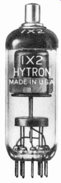
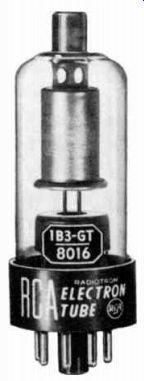
------------ A high voltage rectifier used in television receivers. The
plate connection is through the cop on top. Courtesy CBS-Hytron.
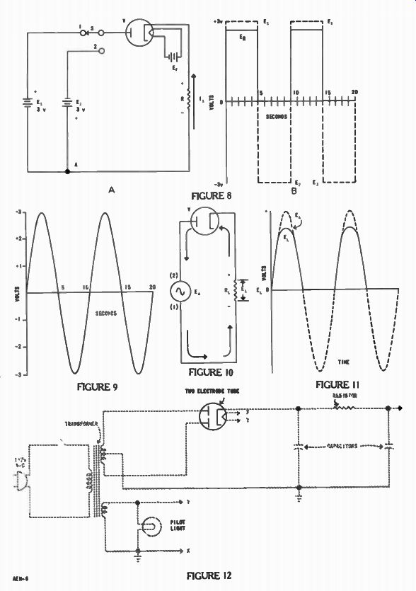
One of the very important applications of the diode is shown by the circuit in Figure 8A. This is the same circuit as Figure 7A except that diode V has been inserted between the switch S and resistor R. The battery E, does nothing except furnish power for the heater of tube V. With the switch in Position 1 as shown, battery E, applies a positive voltage to the plate of V. Since the negative terminal is connected to the cathode through resistor R, electrons flow from this negative terminal up through R, by emission from the cathode to the plate of tube V, and then back through switch S to the positive terminal of battery E1. So long as this is true the voltage across R would be nearly +3 volts with respect to point A. However, when the switch is in Position 2 no electron flow would occur since the negative terminal of E2 connected to the plate of V would make the plate negative with respect to the cathode. As explained for Figure 6, no electrons are emitted by the plate.
Therefore, for Position 2 of the switch the voltage across R would be zero.
The waveform for the voltage across R in this type of circuit is shown in Figure 8B. For the first 5 seconds, almost the same situation exists as pictured in Figure 7B. However, the voltage across the resistor R and the small voltage that appears across tube V are in series. Therefore, the total of these two voltages must add to equal the applied voltage. As a result, the voltage across the resistor which we can label as ER is always a little less than the applied voltage E1. In Figure 8B this is represented by having the solid line wave-form for E_R slightly below the dotted line for E1.
From 5 to 10 seconds with the switch moved to Position 2 no current is possible and so the voltage across the resistor would be zero. This is indicated by the heavy wave-form line directly on the zero reference line during the time that E2 is shown at -3 y by the dotted line. After 10 seconds, if the switch is flipped back to Position 1, across R again would be almost + 3 volts.
From this waveform it is easy to see that no negative voltage ever appears across the resistor ih Figure 8A. It is always about + 3 volts or zero due to the action of the diode. When a diode is used to take an alternating voltage as pictured in Figure 7B and convert it to a direct voltage as shown in Figure 8B, it is called a rectifier and the process is called rectification.
Although an alternating voltage and current is produced in Figure 7A, by flipping the switch back and forth, it is not a practical means of doing so. In power stations throughout the country, large rotating machinery called alternators develop an alternating current which is conducted by wires to factories, stores, and homes for use.
However, the wave-form for this alternating voltage is not like Figure 7B. Instead it continually changes in value as shown in Figure 9. Starting at zero it builds up to a peak which is shown here as +3 volts. Then it decreases through zero and goes negative to a --3 volts. Finally after 10 seconds it returns to zero. In this case each successive instant of time has a slightly different voltage. Although we show a wave form that goes through a complete "cycle" of events in 10 seconds, the voltage most often en countered goes through this same cycle 60 times per second and, in stead of 3 volts, from + 165 volts to -165 volts.
As shown in Figure 10, frequently a source of alternating voltage is shown as a circle with the wave-form inside and labeled EA. This symbol serves the same purpose for alternating voltages as a battery symbol does for direct voltages.
BASIC RECTIFIER CIRCUIT
Figure 10 also shows how a diode rectifies this type of alternating current. The a-c source, represented by its circle, the rectifier V, and the load or equipment using the power which is represented here by resistor EL all form a series circuit. Although the heater for V is not shown in the tube symbol, it is assumed to be there. It is left out of many diagrams because it is a complete circuit in itself and does nothing more to the circuit than heat the cathode.
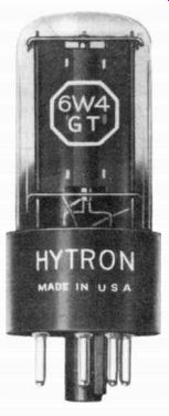
------------ Note the large metal surface which is the plate in this octal
type rectifier popularly used in TV receivers. Courtesy CBS-Hytron.
In operation, the alternating voltage E_A makes the plate of tube V alternately positive and negative with respect to the cathode. Whenever E, makes the plate of the rectifier positive, the tube permits current in the circuit in the direction of the arrows. This current produces a voltage EL across resistor RL. The polarity of EL is indicated by the " + " and " -" signs. When the applied voltage E. makes the plate of the tube negative, the tube does not con duct. Then, with no current in the circuit, there is no voltage across RL. Thus, by allowing current in the direction of the arrows only, the rectifier tube converts the alternating applied voltage to a direct voltage across the load resistor R1. That is, there is a voltage as indicated across RL when V conducts, but no voltage across this resistor when V is not con ducting.
The load voltage EL varies as shown by the solid line curve in Figure 11. Here, the dashed line curve indicates the variations of EA with respect to Point 1 in Figure 10, and with respect to this same point, the solid line curve shows that EL consists of a series of positive "pulses" having the same shape as the positive portion of the wave-form. Since the voltage E,, and a small voltage across tube V are in a series circuit with E,„ E1 , will be slightly less than EA. This is shown in Figure 11 by having the solid line for EL slightly below EA.
AN ELECTRONIC POWER SUPPLY
So far we have shown how a diode converts an alternating cur- rent into a d-c current. However, Figure 10 is not the complete circuit usually found in practical equipment. Several other components are needed. These include an a-c source, transformers, capacitors, resistors, and frequently two diodes in one tube envelope V6 as shown in Figure 12. Al though all of these components are used in many different circuits, one of their important applications is the power supply shown in Figure 12.
As shown by the solid symbol for V in Figure 12, the basic action of these diodes has been described. The remainder is printed in broken lines to show that they need to be described yet. To understand fully how this circuit works, we must learn more about each of these components.
It so happens that the machinery used to generate a-c at the power station and transformer T6 both depend on the action of magnetic fields on a wire. Therefore, in order to understand how these work, the next lesson describes magnetism and some of its important characteristics.
IMPORTANT DEFINITIONS
ANODE-[AN ohd]-See Plate.
CATHODE-[KATH ohd]-In an electron tube, that electrode from which the electrons are emitted or liberated.
DIODE-[DIGH ohd]-A two-electrode tube.
ELECTRON EMISSION-[i LEK trahn i MISH 'n]-The escape of electrons from the surface of certain materials.
ELECTRON TUBE-[i LEK trahn too : b]--An arrangement of two or more conductive elements, enclosed in an evacuated envelope, which can control the electron flow in a circuit.
FILAMENT-[FIL un muhnt]-In an electron tube, a heating element that also serves directly as the emitting cathode.
HEATER-In an electron tube, the element that supplies the heat to an indirectly heated cathode.
PLATE--In an electron tube, that electrode toward which the main movement of electrons takes place. Also called the anode.
PLATE CURRENT--In an electron tube, the electron flow from cathode to plate. In the external plate circuit, the electron flow from the plate, through the circuit, to the cathode.
PLATE VOLTAGE--In an electron tube, the difference of potential between plate and cathode.
RECTIFICATION--[rek ti fi KAY sh'n]-The process of converting a-c to d-c.
RECTIFIER-[REK ti figh er]-A device that converts a-c into d-c by permitting a relatively large current in one direction, and zero or negligible current in the other.
SPACE CHARGE--In an electron tube, a cloud of free electrons surrounding the cathode.
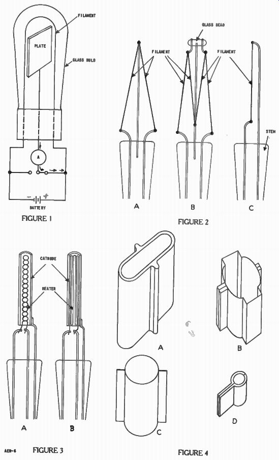
------------ FIGURE 1 FIGURE 2
FIGURE 3 FIGURE 4
--------- FIGURE 6-7
--------------- FIGURE 8-12
FROM OUR Director’s NOTEBOOK
MONEY IN GADGETS
For the man who can think and scheme, a successful business frequently springs up from some simple idea. Many a fortune has been made on small gadgets that originally were intended merely as o personal convenience.
It we check through our Government potent files we find some patents that have been issued on rather complex mechanisms and process but we will also find a much larger number that protect only some simplicity little device that is simplicity in itself. But by its very simplicity it represents an original idea, and further. It is this simplicity that makes the idea useful and valuable.
No one on see into the future, but there certainly are numerous devices on gadgets that could be applied to radio and electronic equipment to increase use, such use of usefulness. With 100 million radio sets in practical gadget would find a big market. Yes, opportunity still lies ahead.
Yours for success,
-DIRECTOR