AMAZON multi-meters discounts AMAZON oscilloscope discounts
Lesson AEH-7A
626 Roselawn Ave., Toronto 12, Ontario
4141 Belmont Ave., Chicago 41, Illinois
ELECTRONS GUARD FIRE HAZARDS
Should a sudden blast of wind blow out the pilot light on a modern gas burner, a valve snaps shut to prevent gas asphyxiation or an explosion. Thus, no longer are these burners the hazard they used to be, and the improvement is due to the incorporation of an electronic device called a thermocouple. So long as it is heated by the burning pilot light, the thermocouple generates an electric current that energizes a solenoid which locks the valve open. When the pilot light is out, no current is generated, and the valve re mains closed.
In addition to this use, thermocouples are employed to measure temperatures, control furnaces and ovens, actuate fire alarms, and operate various other types of thermal-safety devices.
MAGNETS AND ELECTROMAGNETS
Contents
Magnetic Materials
Natural Magnets
Artificial Magnets
Magnet Poles
Magnetic Fields
Attraction and Repulsion
The Effect of Distance Magnetic Induction Molecular Theory of Magnetism Reluctance Changing the Magnetic Field Testing Magnets Electromagnetism Behavior of a Compass in a Magnetic Field Magnetic Field Around a Wire Carrying Current Left Thumb Rule Magnetic Field Around a Coil Left-Hand Rule Ampere-Turns Effect of an Iron Core in a Coil Magnetic Circuits Uses of Electromagnets
If you wish your merit to be known, acknowledge that of other people.
-Oriental Proverb
MAGNETS AND ELECTROMAGNETS
Magnets and electromagnets have a multitude of uses-every electric motor and generator re quires a very strong magnetic field for its operation and with the exception of a few special types, all use electromagnets. Many headphones and loudspeakers have electromagnets, and their operation depends on changes of the electric current in their winding or coil. Corresponding variations in the strength of the magnetic field cause a headphone diaphragm or speaker cone to vibrate and set up sound waves which reproduce the voice or music being broadcast by radio.
Telegraph instruments use electromagnets to attract a movable arm that produces the clicking noises by which messages are received. Such movable arms are called armatures.
Mounted on cranes and hoists, very large electromagnets are used to lift large pieces of iron or steel. These magnets can hold several tons of metal, and are used extensively in foundries, machine shops, and steel mills for loading and unloading cars, or moving metals to various parts of the shop.
Magnets are found in practically every electronic application.
For instance, in a small table model radio, there is at least one and in a color television set, there may be as high as a dozen. This does not include the parts which depend upon magnetic effects. If we include these, a typical radio would have about six and a color television receiver at least thirty.
MAGNETIC MATERIALS
The exact nature of magnetism is not known, but a careful and thorough study of magnets and their actions shows that all materials are affected to some extent when brought close to a strong magnet. By testing all the known substances, it has been found that iron and steel are affected very strongly, cobalt and nickel to some 'extent, while all the others only slightly. In fact, the difference is so marked that iron and steel are called magnetic sub stances or ferromagnetic, the prefix "ferro" being taken from the Latin word "ferrum" which means iron.
The magnetic effect on iron is so much greater than that on cobalt and nickel, that iron is the only magnetic element which by itself is of commercial importance. However, certain combinations or alloys of iron, cobalt, and nickel are in common use because of their superior magnetic qualities.
NATURAL MAGNETS
Any magnet found in a natural state is known as a "natural" magnet. Deposits of magnetic ore have been discovered at various places, one of the largest being in Labrador. Pieces of this magnetic ore, known as "magnetite", are natural magnets. The earth itself is considered as a huge natural magnet because it possesses the same properties as smaller magnets. This makes possible navigation by means of acom pass.
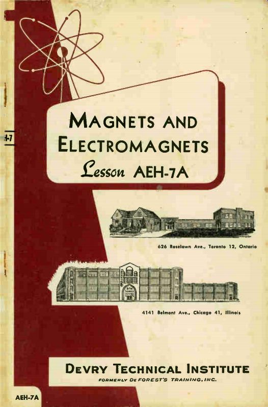
------------ An assortment of horseshoe and bar magnets. The one on the
right is sometimes called a "U" magnet. Courtesy Central Scientific
Co.
ARTIFICIAL MAGNETS
Due to their irregularities in size, shape, and strength, natural magnets have little commercial value. When held in contact with a magnet, a piece of steel becomes a magnet, and by the proper treatment called aging, it can be made to keep its magnetism almost in definitely. For this reason, when properly magnetized and treated, a piece of steel is called a permanent magnet.
While almost any kind of steel can be made into a permanent magnet, some of the alloys mentioned earlier can be magnetized more strongly than ordinary steel.
The most popular magnetic alloy that is used today for permanent magnets is "alnico", an alloy of pure iron, aluminum, nickel, and cobalt. By using these metals in different percentages, various magnetic qualities can be imparted to the alloys. Some of the important applications of such alnico permanent magnets are parts for television, radar equipment, and electron measuring instruments.
When in contact with a permanent magnet, a piece of soft iron becomes magnetized as strongly as a piece of steel, but immediately after the magnet is removed, the iron loses practically all of its magnetism. There fore a piece of iron, especially soft iron, is called a temporary magnet. Furthermore, since they do not occur in a natural state, all forms of magnetized steel and iron can be considered as artificial magnets.
MAGNET POLES
When a bar magnet is suspended or pivoted, it rotates to a general north and south direction,
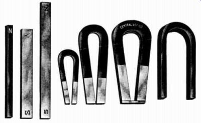
------------ A small magnetic compass. The blue end of the magnetized
needle is the north seeking pole. Courtesy Central Scientific Co.
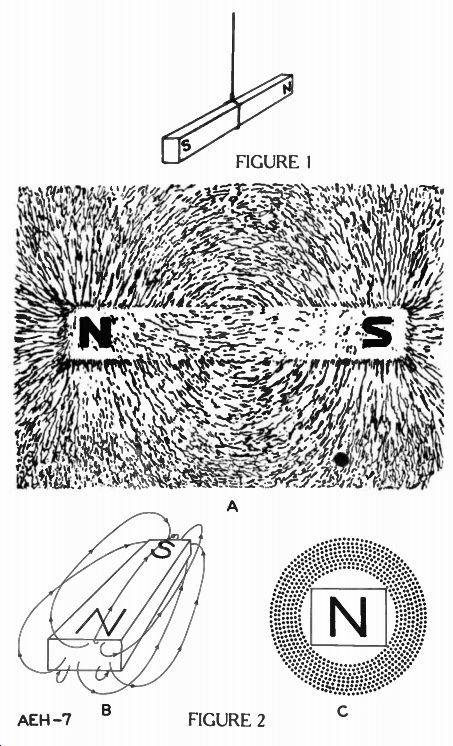
with the same end always pointing toward the north. To illustrate this action, in Figure 1 a bar magnet is suspended by a string so that it swings readily. No matter which way it is pointed, when released the magnet always will come to rest pointing approximately north and south.
The end of the bar magnet that points toward the north is called the north pole, and the end that points toward the south, the south pole. Whenever a permanent mag net has its ends marked "N" and "S", these indicate its north and south poles.
MAGNETIC FIELDS
A magnet is capable of doing some surprising things. When placed close to one end of it, a small piece of iron, such as a nail, actually jumps a quarter of an inch or more to reach the magnet.
The fact that the iron jumps to the magnet shows very clearly that its magnetic effect extends for some distance around it. This area of influence in the space around the magnet is known as the magnetic field, which for convenience, is visualized as being made up of magnetic lines of force. The magnetic field extends outward around the magnet regardless of the materials in this space. Thus, glass, paper, air, or a vacuum present no opposition to magnetic lines of force.
A simple but effective method of making a magnetic field "visible" is to place a piece of ordinary glass over a bar magnet and then sprinkle iron filings on the glass. Under these conditions, the filings arrange themselves in definite lines to produce the general pattern shown in Figure 2A. Notice that these lines appear to extend from the north to the south pole of the magnet. These are thought of as lines of force, and it is assumed that they leave the "N" pole and enter at the "S" pole, so that if fully drawn, each one will form a closed loop from "N" to "S" outside the magnet and from "S" to "N" within the magnet.
In thinking of the action of these lines, just imagine that they are small rubber bands, stretched quite tight. Under this condition the rubber bands will try to shorten or contract, and that is exactly what the magnetic lines try to do. Moreover, they crowd each other somewhat and try to push sidewise but never touch. Figure 2B is a perspective drawing illustrating that the magnetic lines are three dimensional, that is, entirely about the magnet. Figure 2C is the same magnet viewed from the end of the north pole.
Although these magnetic lines extend indefinitely out into space, only a few are shown in the space near the magnet where the effect is strong enough to be useful.
In addition to providing a convenient means of explaining the action of a magnetic field, the theoretical lines of force also provide a means of measurement.
In practical work, magnetic fields have a comparatively large number of lines and are of all shapes and sizes. Therefore, they usually are described as having a certain number of lines per square inch, which means the number of lines that will pass through each square inch of a surface that is placed squarely across the magnetic field.
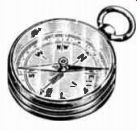
-------------- This permanent magnet is used in electric meters. A small
electromagnet is placed in the cylindrical opening between the poles of the
magnet. Courtesy Burlington Instrument Co.
Because a given number of lines of force may be spread over a comparatively large field or compressed into a relatively small field, it is necessary to know both the number of lines and the size of the area through which they pass. Thus, the number of lines passing through a given area is known as the density of the field.
To combine the number of lines and the area into a single unit, one line per square centimeter is called a gauss, in honor of the German physicist Karl F. Gauss (1777-1855) . A centimeter is .393 inch. Thus, when a magnetic field has a density of 10,000 gausses, it means a magnetic field with 10,000 lines of force per square centi meter.
ATTRACTION AND REPULSION
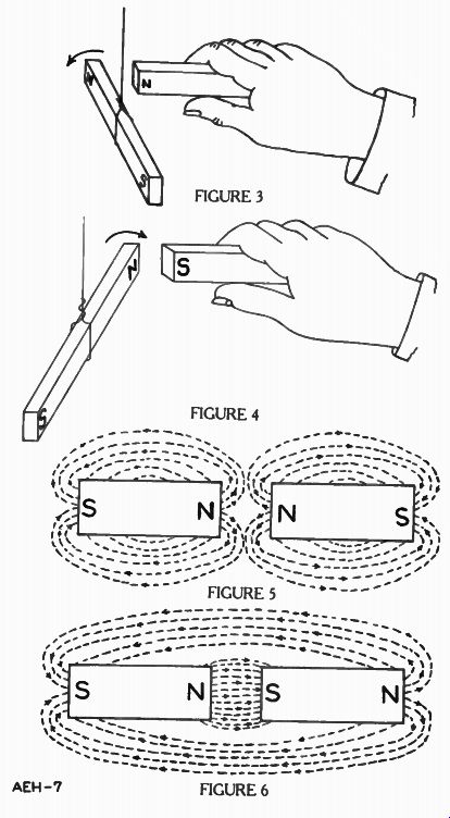
Figure 3 shows the magnet mentioned earlier in the lesson, suspended on a string and left free to turn. It is marked with an "N" on the end that points north and an "S" on the end that points south, and to find out just how two magnets act toward each other, a second magnet is marked in the same manner.
To begin, the second magnet is held with the "N" end forward, and brought slowly toward the "N" pole of the magnet hanging on the string. As the two "N" poles approach each other, the magnet hanging on the string turns away from the magnet in the hand as indicated by the arrow. The action is the same as though the held magnet was actually touching and pushing the magnet on the string. However, since the magnets do not touch, it is the force of the magnetic field which causes the action.
Next, the held magnet is turned so that the "S" pole is forward, as shown in Figure 4, and again brought slowly toward the mag- net on the string. Now the "N" pole of the hanging magnet turns toward the "S" pole as indicated by the arrow, and when close enough, swings over until the magnets touch.
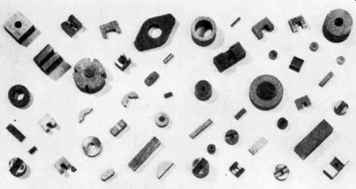
--------------- For various applications, permanent magnets are fashioned
into a wide variety of shapes and sizes. Pictured are a few representative
types. Courtesy General Electric Co.
If the "S" pole of the held mag net is moved toward the "S" pole of the magnet on the string, it will turn away exactly as it did when the "N" poles were brought close together.
These simple tests prove one of the important laws of magnetism, which is: LIKE MAGNETIC POLES REPEL EACH OTHER AND UNLIKE POLES ATTRACT EACH OTHER. This same action can be shown by using the plan explained for Figure 2A. This time two mag nets are used and placed in line with their "N" poles about one inch apart. A piece of glass is then placed over the magnets and iron filings are sprinkled on the glass.
By gently tapping the glass, the filings will arrange themselves in lines which curve away from the end of each magnet as shown in the simplified sketch of Figure 5.
It is customary to sketch magnetic fields on this plan because it is much easier than the drawing of Figure 2A, and yet it sup plies the desired information.
By turning one of the magnets around as in Figure 6, and bringing a "N" and "S" pole about an inch apart when the filings are again sprinkled on the glass, they arrange themselves in almost straight lines right across the gap between the "N" and "S" poles.
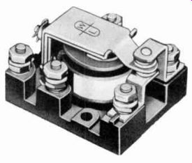
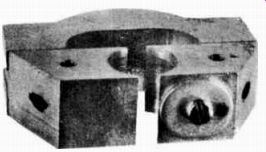
----------------- A typical relay. When current passes through the coil,
the electromagnetic field attracts the armature directly above it. In moving
down, the armature opens one contact and closes the other. Courtesy Ward Leonard
Electric Co.
Think of these magnetic lines as always forming a complete circuit, similar to an electric circuit, except that they will pass through every known substance and travel from the "N" pole, out around to the "S" pole, and then back through the magnet to the "N" pole again.
With this in mind, Figure 5 shows that the magnetic lines of each magnet turn around toward its own "S" pole and have nothing to do with those of the other magnet. In fact, it looks as if they were trying to crowd each other out of the way. On the other hand, in Figure 6 the lines go straight across from the "N" pole of one magnet to the "S" pole of the other, and one magnetic circuit is completed through both of the magnets.
The action of a compass can be explained in a similar manner.
The earth is like a huge magnet around which there is a magnetic field. The north magnetic pole of the earth is near the South Geographic Pole and the south magnetic pole is located close to the North Geographic Pole. There fore, when a compass needle is permitted to move freely in the earth's magnetic field, it will point in a general north and south direction by virtue of the attraction of unlike poles.
THE EFFECT OF DISTANCE
Going back to Figure 2A, the magnetic lines form complete loops which appear to meet at a point near each end of the bar.
These points are the real poles of the magnet. The pull of the mag net on a piece of iron will change with the number of magnetic lines passing through it. Since The lines are concentrated at the poles, the closer to a pole a piece of iron is moved, the more magnetic lines will be passing through it, and therefore, the stronger the pull will be.
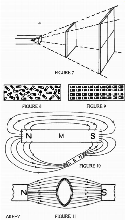
Looking at Figure 2A again, notice that as the lines leave the poles, they spread out in all directions, and if the piece of iron is moved further away from the pole, there will be fewer lines passing through it and the pull on it will be less. This reduction in pull changes quite rapidly, and Figure 7 shows the reason.
A piece of iron that is one inch square is placed one inch from the end of the magnet. Suppose there are 100 lines passing through this piece of iron. If an other piece of iron is placed two inches away from the magnet, it cannot be less than two inches on each side in order to have these same 100 lines pass through it.
The area of the second piece of iron is now 2 times 2 or 4 square inches.
Yet, for this greater area, the same number of lines are passing through it as through the one inch square. Therefore, only 25 lines pass through each square inch of the material. As a result, by doubling the distance the attraction is reduced to one fourth. To express it as a general statement, the strength of the fields decreases by the square of the distance from the starting point.
MAGNETIC INDUCTION
Experimenting further with magnetism it is found that when a piece of iron, such as a nail, is hung on the end of a magnet, it also becomes magnetized and at tracts and holds a second nail.
This one in turn becomes magnetized and will attract and hold a third nail. In fact, if the magnet is strong, a string of nails can be formed. However, no matter how carefully the magnet is removed from the first nail, the string falls apart instantly. Being made of iron, the nails are only temporary magnets which do not retain their magnetism.
MOLECULAR THEORY OF MAGNETISM
Many actions of magnetism can be explained by the molecular theory. This theory states that all materials are made up of very small particles called molecules and, each molecule can be considered an extremely small permanent magnet with a N and S pole.
In iron and steel, these molecules are stronger magnets than any of the other metals.
As shown in Figure 8 where the black end is a N pole and the other end is a S pole the molecules in the ordinary piece of iron or steel are not arranged in any particular order, and so their magnetic fields cancel out within the metal. However, since unlike poles attract each other, when the iron or steel is put in a strong magnetic field, the molecules all turn in one direction, as in Figure 9.
Then the individual magnetic fields combine to make the entire piece of metal act as one large magnet, the N pole on the right and the S pole on the left.
RELUCTANCE

------------ The cylindrical shaped metal inside the U shaped frame at
the rear of the speaker is a permanent magnet. The speaker also employs an
electromagnet, not visible in this picture. Courtesy Permoflux Corp.
Because most of the molecules of soft iron turn quite easily un der the influence of a magnetizing force, the overall magnetic effect is quite strong. In some other materials, very few or none of the molecules will turn because of the rigid structure of the material. In other materials the magnetic field for each molecule is quite small. In either of these cases, the total magnetic effect is very weak.
Although magnetic lines of force will pass through all sub stances, some materials do not carry them as readily as others.
This opposition which a substance offers to the passage of magnetic lines is known as its reluctance.
Reluctance is a property of every material. Just as there is no perfect conductor, there is no material capable of passing all magnetic lines. However, for practical purposes, soft iron has a very low reluctance.
CHANGING THE MAGNETIC FIELD
Referring to Figure 10, when a bar of soft iron B is placed in the field of a permanent magnet M, the magnetic lines that pass through the iron cause it to be come a temporary magnet having a N and S pole as explained for Figure 9.
Since soft iron offers less reluctance to the passage of magnetic lines than the surrounding air, the lines of force leaving the N pole of the permanent magnet are attracted by the S pole of the soft iron, and the lines leaving the N pole of the temporary magnet are attracted by the S pole of the permanent magnet. Thus, the magnetic field is pulled out of its natural shape.
Sometimes the path of a magnetic field is purposely changed as shown in Figure 11. So far as anyone knows, magnetic lines will pass through any material. In making up the magnetic fields with iron filings in the earlier part of this lesson, the magnet was placed under a piece of glass and iron filings were sprinkled on top. The glass, which was used as an electric insulator had no more effect toward insulating magnet ism than the air itself.
To prevent magnetic lines from passing through any object, such as a watch, it is necessary to en close it in an iron case. Being a magnetic substance iron carries the magnetic lines so much easier than air or other materials that, instead of passing through the watch, the field is distorted and passes around it through the iron.
This arrangement is called a "magnetic shield", and as indicated in Figure 11, the space in side the iron shield has no magnetic lines passing through it.
TESTING MAGNETS
A very simple way of testing the strength of a permanent mag net is to place a bar of iron across its poles, and then by using a spring type of weighing scale, see how many pounds pull is required to remove the piece of iron.
Also, there are "flux meters" which are placed across the poles of the magnet to be tested and their action is very similar to the method explained above, except that the lines of the magnetic field pulls a pointer across a calibrated scale.
ELECTROMAGNETISM
It has been found that an electric current sets up a magnetic field much like that produced by a permanent magnet. This action, known as electromagnetism, is of extreme importance in a large percentage of electric and electron apparatus for it permits complete control of magnetic fields.
In order to demonstrate the existence and properties of a magnetic field that is produced by an electric current, the experiment shown in Figure 12 is used.
A wire is forced through a piece of cardboard and connected to a voltage source so that electrons in the wire will flow from negative to positive, as shown by the vertical arrows.
If a magnetic compass is placed on the cardboard and is moved in a circular path around the wire, the compass needle no longer will point north and south. It changes direction continuously as thecom pass is moved about the wire.
Since the compass needle is a small permanent magnet there must be a magnetic field present, other than the earth's field, which deflects the pointer in this manner.
When there is no current in the wire, the compass will point north and south regardless of its position on the cardboard. Therefore, it is reasonable to decide that it is the current and not the wire that produces the magnetic field.
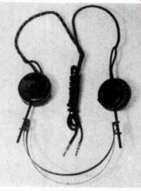
-------------- A typical pair of earphones. Sound is produced when the
electromagnets cause the thin steel diaphragms to vibrate. Courtesy C. F. Cannon
Co.
Similar to permanent magnets, the magnetic field intensity is greatest near the wire and decreases with the distance between the wire and the compass.
BEHAVIOR OF A COMPASS IN A MAGNETIC FIELD
Referring back to the laws of magnetism, if the magnetized needle of the compass is placed in a magnetic field, its N pole will turn away while its S pole is attracted towards the other N pole.
The same effect will take place at the S pole, but in the opposite direction. The result is a double action, a pull on one end and a push on the other, and this double action causes the compass needle to line up with the magnetic lines of force in which it is placed.
When moved around the wire, as shown in Figure 12, the changing positions of the compass needle will trace a circle, there fore, the magnetic field around the wire is circular in shape. Raising or lowering the cardboard along the wire has no effect on the action of the compass, and it continues to trace a circle as it is moved around the wire.
This magnetic field around a straight wire can be visualized as a solid cylinder as shown in Figure 13. The magnetic field exists uniformly along the wire: that is, at two points the same distance away from the wire, the lines are equally dense.
MAGNETIC FIELD AROUND A WIRE CARRYING CURRENT
To continue this investigation of electromagnetic action, the connections of the circuit of Figure 12 are reversed so the electrons pass down through the wire.
Now when the compass is moved around the wire, it still points a circle but in the opposite direction.
Thus, when the direction of electron flow is up through the wire in the cardboard, thecom pass needle points in a clockwise direction. When the circuit connections are reversed so that the electron flow is down through the wire, the compass needle reverses its direction and points in a counterclockwise direction.
LEFT THUMB RULE
The above actions show that there is a definite relationship between the direction of electron flow and the direction of the magnetic field it produces. It so hap pens that the thumb and fingers of the left hand can be used as a convenient means of determining this relationship. For example, as shown in Figure 14 BY HOLDING THE WIRE IN THE LEFT HAND, WITH THE THUMB POINTING IN THE DIRECTION OF THE ELECTRON FLOW, THE FINGERS WILL SUR ROUND THE WIRE IN THE SAME DIRECTION AS THE MAGNETIC FLUX. This is called the "Left Thumb Rule". This simple rule is very useful, because if the direction of the electron flow is known, the direction of the magnetic field can be found; or should the direction of the magnetic field be known, the direction of the electron flow can be determined.
MAGNETIC FIELD AROUND A COIL
To continue with the investigation, the wire of Figure 12 is taken out of the cardboard and bent into a loop as in Figure 15. Using the left thumb rule, when the electron flow is in the direction shown by the arrows, the fingers point around toward the in side of the loop no matter on which part of the wire the hand is placed.
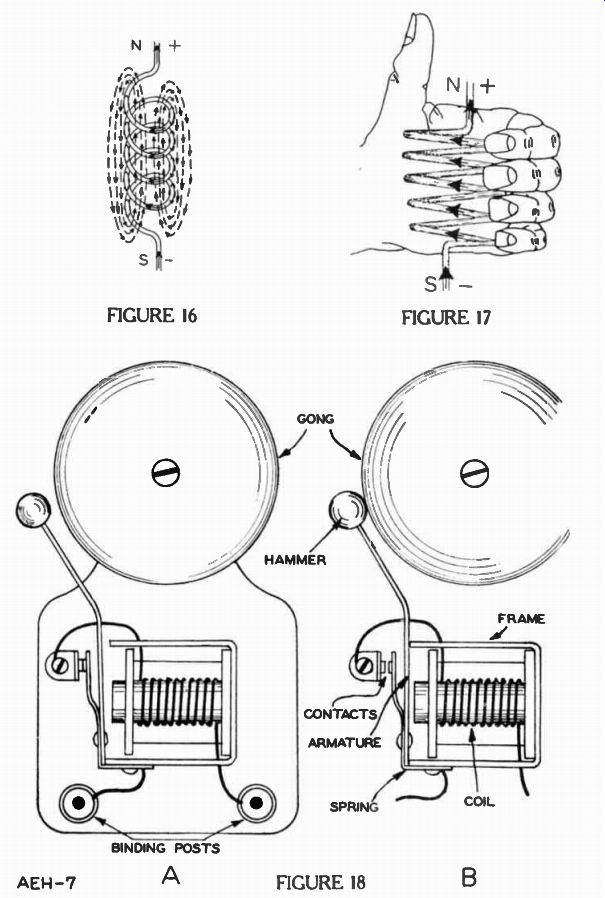
To investigate still further, the wire is bent into several loops, or a "coil", as in Figure 16, and then connected to an electric circuit that carries electrons in the direction of the large arrows. If a magnetic compass is moved around the inside and outside of the coil, it will indicate that the magnetic lines surrounding each turn of the wire separately, appear to combine into one continuous magnetic field of the form and in the direction shown by the light broken lines.
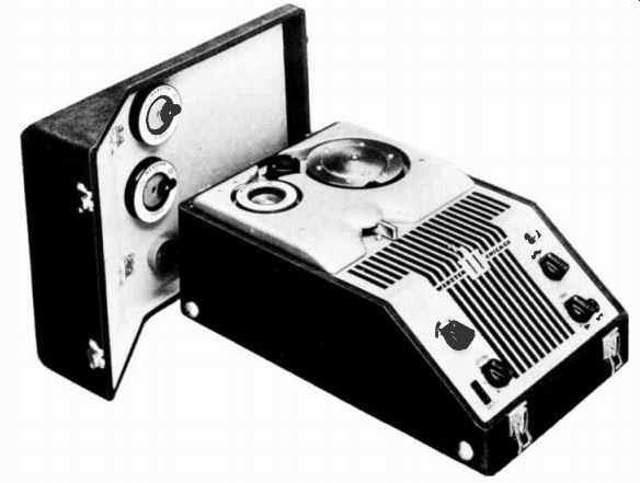
------------ A wire recorder utilizes an electromagnet which magnetizes
a special type of iron wire. Although easily magnetized the wire retains the
magnetism. Note the extra spools of wire in the cover. Courtesy Webster-Chicago
Corp.
Note that this flux is similar to that set up by a permanent magnet, with the N pole at the upper end where the compass shows the magnetic lines coming out of the coil. So long as current exists, the coil acts like a permanent mag net. It has an N and S pole ; and, if free to turn in a horizontal plane, the coil will come to rest pointing North and South.
LEFT-HAND RULE
As with the straight wire in Figure 12, there is a definite relation between the direction of the current and direction of magnetic flux around a coil. As shown in Figure 17, WITH THE FINGERS POINTING AROUND THE COIL IN THE DIRECTION OF THE ELECTRON FLOW, THE THUMB WILL POINT TOWARD THE N POLE OF THE MAG NETIC FIELD. This is called the "Left-hand Rule", and can be used whenever the wire is looped or coiled, and the direction of electron flow is the same through its entire length.
In a coil like that of Figure 17, it has all the magnetic qualities of a permanent magnet so long as current exists. Moreover, an increase of current in the coil increases the strength of the magnetic field, and a decrease of current weakens the field.
AMPERE-TURNS
When the number of loops or turns of the coil is increased, but the current remains the same, the strength of the magnetic field will increase. Each loop or turn of the coil sets up its own magnetic field which unites with the fields of other loops. Hence, the more loops, the more magnetic fields unite and reinforce each other, and as the result, the total magnetic field is stronger.
To compare the magnetic strength of different coils, and to obtain a basis for measuring them, it is useful to multiply the number of turns of wire by the number of amperes of current carried by the wire and call the result ampere-turns. For example, a coil with 10 turns and a current of 10 amperes will have 100 ampere-turns. Another coil with 50 turns and a current of 2 amperes also will have 100 ampere-turns.
EFFECT OF AN IRON CORE IN A COIL
Earlier in this lesson, it was stated that iron and steel have low reluctance and carry magnetic lines of force much more readily than air and other materials. To increase the magnetic field of a coil, it is common practice to insert a piece of iron through the center of the coil like that shown in Figure 16. The iron is called the core, and its low reluctance permits many more magnetic lines of force than the air could possibly carry. The complete assembly of a coil with an iron core is called an electromagnet.
The magnetic behavior of a coil carrying an electric current can be summed up in the following three statements:
1. Whenever a current of electricity is present in a coil of wire, a magnetic field is set up in and around the coil, which then exhibits all the properties of a magnet.
2. The strength of the magnetic field varies with the number of turns and the current. With no current, there is no magnetism.
3. An iron core placed inside the coil, permits a large increase in the strength of the magnetic field.
MAGNETIC CIRCUITS
Magnetic action is understood better by thinking of the paths taken by magnetic lines of force in much the same way as the current paths in an electric circuit.
In an electric circuit, pressure or voltage overcomes the resistance of the conducting path and sets up a current of electricity. In a magnetic circuit similar conditions exist, but instead of a voltage, there is a magnetomotive force (mmf), which causes magnetic lines through the circuit.
The opposition which the magnetic circuit offers to this flux is known as reluctance. Electrically, nearly all materials have different resistance characteristics some offering little and others high op position to an electric current.
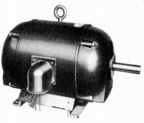
-------- This motor depends on electromagnetism for its operation. The
attraction and repulsion between the magnetic poles causes the armature to
rotate. Courtesy Robbins and Meyers, Inc.
However, with the exception of the magnetic metals, most sub stances offer nearly equal reluctance. Iron has low reluctance, while air and other nonmagnetic materials have high reluctance.
In comparing the magnetic circuit with an electric circuit; there is an mmf instead of voltage, lines of force, or flux lines instead of current, and reluctance instead of resistance. The relationship between voltage, and current, and resistance in the electric circuit and the relation ship between mmf, lines of force, and reluctance in the magnetic circuit are very similar. Just like voltage is equal to current times resistance, magnetomotive force is equal to the flux times the reluctance.
USES OF ELECTROMAGNETS
In general, whenever it is desired to produce mechanical motion by means of electricity, some form of electromagnet is used. In almost every instance, the part to be moved is made of magnetic material and placed quite close to the electromagnet. This is done because the pull of a magnet is inversely proportional to the square of the distance between it and the attracted object.
The common door bell is a good example of the use of an electro magnet to produce mechanical motion. In Figure 18A a bell of this kind is shown with the cover removed to expose the main parts that are named in Figure 18B. Starting at the top, you will see the "gong" or bell proper, while directly below it is the armature which has a small ball or "hammer" attached to its upper end.
The coil of wire for the electro magnet is wound on a cylindrical iron core that is riveted to the center of a "U" shaped iron frame. The armature extends across the open end of the "U" of this frame, and is held in position by the spring which is riveted to both the armature and the frame.
The upper end of the spring is bent away from the armature, and carries a contact which is in line with another contact mounted rigidly on the main base, but electrically insulated from it. The spring tension is in a direction to pull the armature away from the frame and to hold the contacts together as shown in Figure 18A. There is an electric circuit from the right hand binding post, up through the turns of the coil and over to the stationary contact. As the spring holds the contacts together, the circuit continues through the spring to the left hand binding post. To simplify the drawing, only a few turns of wire are shown in the coil, but actually several hundred turns are employed to fill the entire spool. The larger number of turns provides a great number of ampere-turns at low currents and thus provides a more satisfactory operating condition.
To put the bell into use, it is connected in an electric circuit which contains a source of voltage and a push button type of switch.
When this circuit is closed by means of the switch, the resulting current is carried by the coil which sets up a magnetic field across the open end of the U shaped magnet frame.
Since the iron armature is located in this field, it will be attracted and move toward the frame as soon as the magnetic pull is strong enough to overcome the tension of the spring. When this happens, the armature moves from the position shown in Figure 18A to that shown in Figure 18B. The movement of the armature does two things. First, the ball on its upper end strikes the gong and causes the bell to ring. Second, the contact on the upper end of the spring no longer touches the stationary contact, and consequently the circuit is opened. As soon as the circuit is opened, the current is interrupted, the magnetic field dies out, and the spring pulls the armature back to the position of Figure 18A. The instant the contacts touch, the circuit is completed, it again carries current, and the entire action is repeated.
The movement of the armature is quite rapid, and therefore, so long as the push button switch is held closed, the armature vibrates with the hammer on its upper end striking the gong each time the magnet pulls it over. While the door bell is a simple example, it illustrates one common method by which the electric current in a coil is converted to a magnetic energy that attracts an armature and causes mechanical motion.
Magnets and electromagnets also are used in reverse. Instead of converting electric power to motion, by using a magnetic field mechanical motion is converted into an alternating voltage or alternating current. Upon this basis the 117 v. a-c is generated both for your house and almost all the equipment used in electronics. A device commonly called a genera tor performs this action, and how it works is described in the next lesson.
IMPORTANT DEFINITIONS
AMPERE-TURN-(NI)---A unit of magnetomotive force or magnetic excitation, equal to the effect of a current of one ampere through one turn of wire.
CORE-A piece of magnetic material that is inserted through the center of a solenoid to provide a low reluctance path for the magnetic lines of force.
ELECTROMAGNET-[i lek troh MAG net]--A coil of wire, wound on an iron core, that exhibits magnetic qualities when it carries an electric current.
GAUSS-[gous] A unit density equal to one line of force per square centimeter.
MAGNET-[MAG net]-An object that exhibits the property of magnetism.
MAGNETIC CIRCUIT-A closed path of magnetic flux.
MAGNETIC FIELD-The space around a magnet in which the magnetic force can be noticed.
MAGNETIC LINES-(i) -Those lines around a magnet along which the magnetic force appears to manifest itself.
MAGNETISM-[MAG ne tiz'm]--A property possessed by iron and its compounds, when in a certain condition, by which it can exert mechanical forces on neighboring masses of iron.
MAGNETOMOTIVE FORCE (mmf)-[mag nee toh MOH tiv fawrs]--The exciting force required to set up magnetic flux within an object.
RELUCTANCE-[re LUK tans]--The opposition experienced by the magnetic flux set up within an object. It corresponds to resistance in an electric circuit.
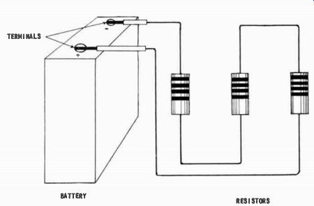
WORK DIAGRAM --Draw pencil lines to represent wires connecting the battery and resistors in a series circuit.
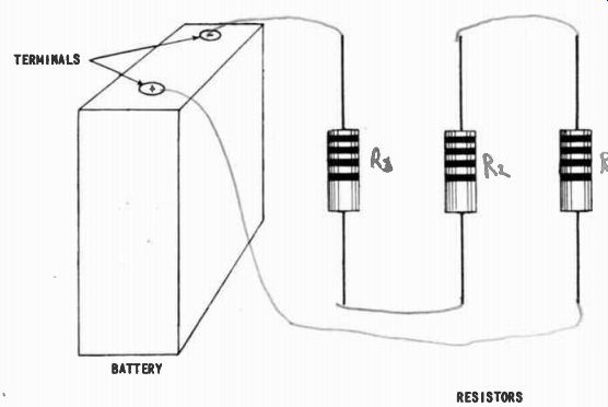
--------- When you have finished, check with the answer on the back of the fold-out sheet.

--------- FIGURE 12
FIGURE 14 FIGURE 15
------- FIGURE 16, FIGURE 17 FIGURE 18
-----------
----------
----------
WORK DIAGRAM SOLUTION Draw pencil lines to represent wires connecting the battery and resistors in a series circuit.
----------
FROM OUR Director’s NOTEBOOK
LAYING THAT FOUNDATION
Oftentimes in the process of a young man's training the question arises, "Why must I learn and do all these seemingly useless things, why can't I get into my chosen work right away and do something?"
Before a child can walk, he must first learn to stand, how to move and place his feet, and finally how to take No horse ever won a race until he had been thoroughly a few steps.
trained in all phases of behavior and action on the track.
Similarly as you go through your radio and electronic training you may become a little impatient at times and wonder why you are put through all these preliminaries.
These preliminaries are all essential toward a better understanding of the more advanced subjects and toward acquiring skill and accuracy in your applied work.
Proficiency comes only with practice and training.
These basic lessons have therefore been included with your training as essential steppingstones toward a successful radio career.
Yours for success,
-DIRECTOR