AMAZON multi-meters discounts AMAZON oscilloscope discounts
ELECTRONS IMPROVE COLOR PRINTING
Colored pictures, such as those found in modern magazines, are made by printing several colors in sequence to obtain the desired final effect. However, to preserve the fine detail in a picture, each color must be located at precisely the same place on the page. Photocells, together with various other electronic devices, control the printing press to provide the precise operation needed.
Popularly known as an "electric eye", the complete list of photocell applications is very extensive. To mention a few, they are used with motion pictures to reproduce the sound, in the light meters employed by photographers and light engineers, to open and close doors, in automatic level controls for elevators, for fire, smoke, and burglar alarms, and for liquid level indicators.
A-C GENERATOR
Contents
Voltage Induced in a Conductor
Factors Controlling the Induced Voltage
Electromagnetic Induction in a Loop
Action As the Loop Is Revolved
Variations in Rate of Cutting the Field
Variation in Direction and Amount of Induced Voltage
Alternating Current
Sine Curve
Cycles and Alternations
A Simple Alternator
Some people fail because they never begin. More people fail because they never finish. Stick-to-it-ive-ness wins oftener than genius or luck. You may make mistakes, others may misjudge you. You may be tired and discouraged. But, if you stick, by and by everything and every body will give way to you.
If you have principles they will do you no good unless you stick to them. If you do not stick to your friends, you don't deserve friends. If you do not stick to your job, you cannot make a success of it and find a better one.
In a troubled and anxious time of the Civil War, General Grant said, "I will fight it out on this line if it takes all summer." Let that be your motto.
-Dr. Frank Crane
A-C GENERATOR
VOLTAGE INDUCED IN A CONDUCTOR
The process of developing a voltage in a wire that cuts across or is cut by magnetic lines of force is known as electromagnetic induction, and this principle is the basis for the operation of all conventional electric generators.
Electromagnetic induction is used also in all types of transformers and coils that are employed in many kinds of electronic apparatus.
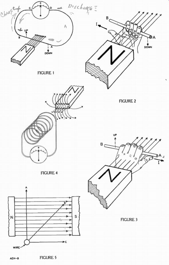
To illustrate electromagnetic induction as simply as possible, in Figure 1 the "N" end of a permanent bar magnet is shown close to an electric circuit consisting of a length of wire, each end of which is connected to a sensitive meter.
For convenience, this particular meter has the zero in the center of the scale, with the values increasing to the left and right of the zero. With no current in the meter, the pointer rests at zero. With current in one direction the pointer swings to the right, and with current in the opposite direction it swings left.
By taking hold of the wire at points "A" and "B" and keeping it close to the end of the magnet, when the wire is moved up quickly, the pointer swings a little and then drops back to zero. Also, when the wire is moved down past the end of the magnet, the pointer again deflects from zero, but in the opposite direction. However, pulling the wire straight away from the end of the magnet has little or no effect on the meter, nor does pushing the wire straight toward the magnet move the pointer.
We know that the pointer will not move unless there is current in the meter and unless there is a potential difference across a circuit, no current can exist in it. Hence, the movement of the pointer with the motion of the wire definitely indicates that a voltage has been induced.
This simple test demonstrates two important facts. First, since the magnetic lines extend out from the end of the magnet, in order to make the pointer swing, the wire must be moved in such a direction that it cuts through or across these lines. Second, the direction in which the meter deflects depends on which way the wire is moved. When the wire is moved up the needle swings in one direction, and when the wire moves down it deflects to the other side of the scale.
Often it is necessary to know the direction of current caused by the induced voltage for a specific direction of motion of the wire.
In order to determine this relationship, the meter can be checked with a dry cell. If the positive and negative terminals of the cell are known, the direction of the current in a circuit connected across the cell terminals is known also.
To make this test, the wire of Figure 1 is removed and terminal C of the meter is connected in series with a resistor to the positive terminal of a dry cell. Then, when meter terminal D is touched on the dry cell negative terminal, the pointer swings to the right. To make certain, the dry cell connections are reversed so that the positive terminal connects through the resistor to meter terminal D while the negative is touched on terminal C. When this is done, the pointer swings to the left.
Therefore, an electron flow from "C" to "D" makes the pointer deflect to the left, and from "D" to "C" moves it to the right. This in formation is all that is needed about the pointer action, so the circuit shown in Figure 1 is re stored.
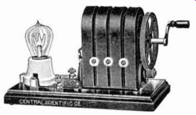
------------ This simple alternator demonstrates how loop rotation speed
affects the voltage. The current resulting from the induced voltage lights
the lamp. The faster the crank is turned, the brighter the lamp glows. Courtesy
Central Scientific Co.
Now, when the wire is pulled up quickly past the end of the magnet, the meter pointer swings to the right. From testing with the dry cell, a needle deflection to the right indicates that "A" is the negative and "B" is the positive of the meter.
Since the circuit is complete, the induced voltage will cause electrons to flow, and their direction will be from "A" to "D", through the meter to "C", along the wire to "B", and back to "A". If the wire is moved down past the end of the magnet, the pointer swings to left and thus indicates that terminal "D" now is connected to the positive end of the wire
and the current in the circuit is from "B" to terminal "C", through the meter to "D", and back along the wire from "A" to "B". Up until now the wire was moved at right angles through the magnetic field to generate a voltage causing a current to deflect the pointer of a meter.
We could just as easily have moved the magnetic field at right angles to the stationary wire to generate a voltage in the wire.
The important thing is that either the magnetic field or wire is moving relative to the other.
Applying the Left-Thumb rule described in the previous lesson, we can find the direction of the current through the wire. Figures 2 and 3 show a section of wire of Figure 1. As used in Figure 2 and 3 the fingers of the left hand corresponds to the direction of the magnetic lines and the thumb points in the direction of the electron flow.
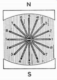
----------- This sketch illustrates how the cutting angle affects the voltage
induced in a loop rotating in a magnetic field. When the loop moves from position
1 to 2, each conductor cuts 1 line, from position 2 to 3, 4 lines are cut,
and the maximum number of 6 lines are cut between positions 4 and 5.
To begin with in Figure 2, hold the fingers of the left hand straight out and close together while the thumb is spread away from the fingers as far as possible. Then with the palm up, place your hand under the wire so that the wire moves into it while the fingers point to the right. Then the thumb points in an upper left direction.
Now the left hand is in the proper position to indicate the current through the wire of Figure 1 when it was moving down ward into the palm of the hand.
A voltage induced in the wire causes the section of wire within the magnetic lines to act as a voltage source or battery for the rest of the circuit. Current then in side the source is from A to B, the same as in Figure 1.
For Figure 3, with the fingers of the left hand extended and the thumb full out, place your hand with the palm down over the wire moving up into it with the fingers still pointing to the right and the thumb pointing to the lower right of the page. This time the thumb indicates that the current is from B to A. This is identical to the direction of the current in Figure 1 when the wire is moved upward, again toward the hand.
Looking from the +A end of Figures 2 and 3 the “x" in Figure 2 indicates electrons flow into the paper or away from you while the "." in Figure 3 shows the flow out of the paper or coming at you.
FACTORS CONTROLLING THE INDUCED VOLTAGE
Not only is it important to know the polarity of an induced voltage or direction of the current in a conductor, but often it is valuable to know the factors that determine how much voltage is induced. In Figure 1, it was explained that in order to have a potential difference, the wire or magnet is moved with respect to the other. Further experiments show that the speed with which the wire or magnet is moved also affects the voltage. The faster the lines are cut, the higher is the voltage induced in the conductor.
To determine these factors that influence the induced voltage, a zero center meter can be connected to a large coil of several turns as shown in Figure 4. A bar magnet, much like that in Figure 1, is shown in position to be pushed into the far end of the coil.
In the previous lesson on magnets, the magnetic lines of a bar magnet were shown coming out of the North pole, fanning out, and going around to the South pole. In Figure 1, only these lines coming straight off the end of the magnet are shown, but in Figure 4, the more important lines are those that fan out in such a manner that they will be cut by the coil when the magnet is moved.
When the magnet is pushed into the coil or the coil is pushed over the magnet, the pointer swings one direction, and when they are pulled apart the pointer moves in the other direction.
After turning either the magnet or the coil around end for end, the pointer still moves but the deflection is in the opposite direction.
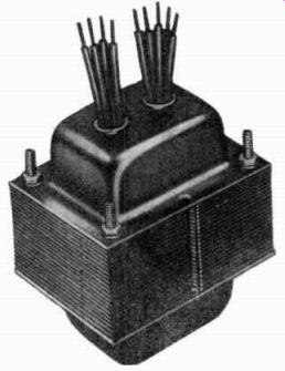
-------- Transformers are used in alternating current circuits only. They
use an alternating current for their operation. Courtesy Standard Transformer
Corp.
Also, by pushing the magnet into the coil more quickly, by adding more turns to the coil, or by adding a second magnet pointing in the same direction as the first, the voltage induced in the coil will be increased.
Another factor that determines the induced voltage is the angle at which the conductor cuts through the magnetic field. To illustrate this action, in Figure 5 the magnetic lines of force or FLUX are represented with light arrowed lines coming out of the "N" end of a permanent magnet and going directly across a gap to a "S" pole. If the wire is moved at some specific speed up to point "A", it will cut through the entire flux at right angles. Moving the wire the same distance at the same speed to point "B" will make it cut about three-fourths of the flux, but moving it at the same speed and distance to point "C", the wire will not cut through any of the flux lines. Therefore, moving the wire to "A" will produce some definite voltage, moving it to "B" will give about three fourths of that value, and moving it to "C" will develop very little or no voltage at all.
Considering all of these effects, the following four factors control the amount of induction:
1. The speed of the motion, or how fast the magnetic lines and the conductor move with respect to each other. The greater the speed, the greater the induced voltage.
2. The length of the wire that cuts through the magnetic field. The longer the wire, the greater the induction. In the case of a coil, the more turns the greater the induced voltage.
3. The strength of the magnetic lines, or the number of magnetic lines per unit area. The stronger the flux the greater the induced voltage.
4. The angle of cutting the magnetic lines changes the induction. The more nearly the wire cuts squarely across the lines, the larger the induced voltage.
These factors can be summed up into one simple sentence which states: THE INDUCED VOLTAGE IS DIRECTLY PROPORTIONAL TO THE RATE OF CUTTING THE LINES OF FORCE. By rate is meant the number of magnetic lines cut by the conductor per second, and the rate can be increased by increasing the speed of cutting, the length of the conductor, the strength of the flux, or the angle of cutting.
An important point to remember is that the action induces a voltage in the coil or conductor and, should the conductor that cuts the magnetic flux be a part of a complete electric circuit, then the induced voltage will cause a current in the circuit. You may read or hear a lot about induced current, but to be technically correct it is a current caused by an induced voltage.
ELECTROMAGNETIC INDUCTION IN A LOOP
To generate voltage and a current, the set-up of Figure 1 is highly impractical. To make the generation of voltage and current easy, rotating machines are built with conductors in the form of loops which turn through a magnetic field. Figure 6 shows the simple form of a generator, but its operation is the same as those turned by water wheels and turbines at a hydroelectric plant.
A permanent magnet sets up a magnetic field for the wire to cut.
Resistor R is external to the generator but completes the electric circuit so that the induced voltage causes a current. With the wire bent into a loop, one side moves closer to the N pole while the other moves nearer the S pole.
Since the loop must move, it is mounted on, but electrically insulated from, a rotating shaft. To connect the loop to the external resistor while the loop turns, each of its ends are connected to a cop per ring also mounted on the shaft. External connections are made to a stationary conductor resting on each of these rings.
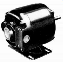
----------- The typical a-c motor found on washing machines, fans, and
refrigerators are alternators operated in reverse. The alternating current
causes the armature to rotate in a magnetic field. Courtesy Robbins & Myers,
Inc.
The rings are called collectors and the stationary conductors are known as brushes. The brushes and rings thus form sliding contacts to connect the rotating loop to the external circuit.
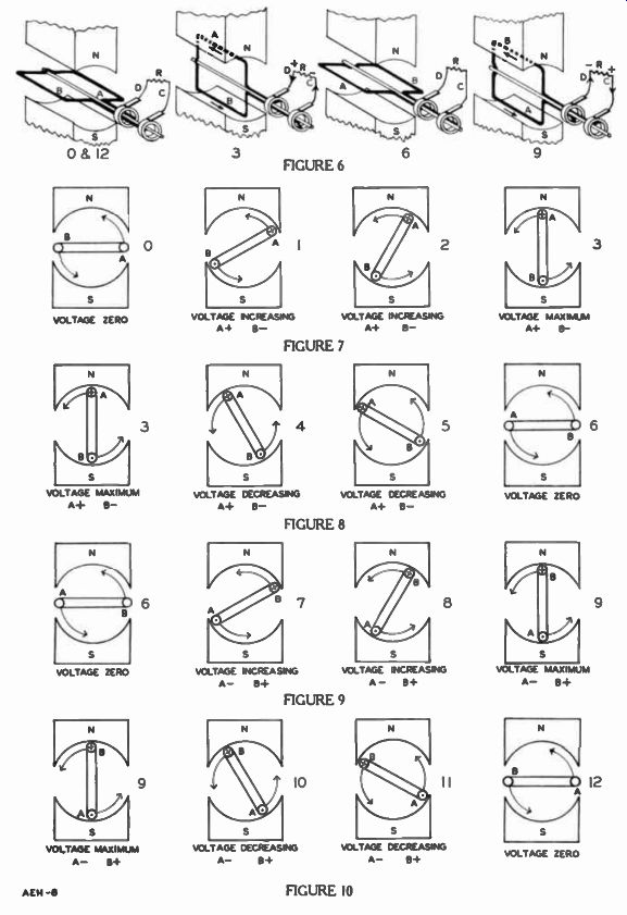
Figure 6 shows the loop in four positions of rotation. For convenience the complete rotation of the loop is divided into 12 positions much like the face of a clock is marked off in hours. Also, as in the clock where 0 o'clock and 12 o'clock is the same position, 0 and 12 Position will be the same point in the rotation of the loop. As on the clock face, 3 will represent the position of the loop after one quarter of the rotation, 6 another quarter of the rotation, 9 the 3rd quarter of rotation, and 12 the complete rotation. Unlike the clock, in this particular illustration the loop starts from a horizontal position and revolves in the reverse or counterclockwise direction.
In Figure 6 Positions 0 and 12, the circuit inside the generator is from the upper left brush D through the ring, along side A of the loop, across the back to side B and forward through the other side of the loop and brush C. Even when the loop is rotated, the circuit and the loop connections do not change.
As the shaft is turned in a counterclockwise direction from Position 0 in Figure 6, side A will go up and left past the N pole of the magnet on top, and side B will go down and right past the S pole on the bottom. By using the Left Thumb Rule, the fingers pointing in the direction of the magnetic flux palm faced so wire moves into it, the thumb indicates the direction of the current caused by the induced volt- age. On the bottom side of the loop this direction is from the back toward the front, or out from the paper. On the top side, which is moving left, the induced voltage will cause a current from the front toward the back, or into the paper.
The action of the two induced voltages maintains a current around the loop, back on the top side A and forward on the bottom side B. Considered sources of electric energy, the induced voltages are connected in series, and will tend to maintain current in the same direction.
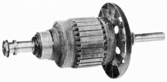
------------ A typical generator rotor having a large number of windings.
Courtesy The Louis Allis Co.
ACTION AS THE LOOP IS REVOLVED
As the loop continues to turn from Position 0 in Figure 6, at the end of a quarter turn it is in Position 3. Here, sides A and B move directly across the magnetic lines and there is a maximum induced voltage.
After the next quarter turn in the same direction, the loop is in Position 6. Notice this condition is exactly the reverse of Position O. Side A is on the left about to move down past the S pole, and side B is on the right ready to move up past the N pole.
As the loop moves past Position 6, the induction is exactly the same as at Position 0, that is, the direction of current is back along the top side and forward along the bottom side. However, the loop has turned over, so the induction now causes current back along B and forward along A which is the reverse direction in so far as the sides of the loop are concerned.
By completing another quarter turn to Position 9 in Figure 6, the conditions of Position 3 are re versed. Side A is now on the bottom and side B on the top. Again there is maximum induction be cause the sides of the loop are moving directly across the magnetic lines. The last quarter turn brings the loop back to Position 12 and since it also is Position 0 the actions will repeat as the loop passes through another complete turn.
To produce a voltage by motion, the principles of electromagnetic induction are used, and by bending the wire into a loop and using both poles of the magnet, the action has doubled. As one side of the loop goes left, the other comes right and the inductive action pushes electrons back on the one side and pulls them forward on the other.
VARIATIONS IN RATE OF CUTTING THE FIELD
Positions 3 and 9 of Figure 6 are conditions of maximum induction, and Positions 0 and 6 are conditions of zero or minimum induction. These conditions are explained by the fact that the induced voltage is directly proportional to the rate of cutting the magnetic field. Earlier in the lesson we stated that the rate of cutting is controlled by four factors:
1. Speed of cutting,
2. Length of the conductor,
3. Strength of the magnetic field,
4. Angle of cutting.
In the simple generator of Figure 6, it is assumed that the Loop is revolving at steady speed in a counterclockwise direction. The length of the loop is fixed, and it cuts through a field of uniform strength. The only remaining factor that can produce a variation in the induction, is a change in the angle of cutting as the loop turns. In Positions 3 and 9 of Figure 6, the angle of cutting is directly across the magnetic lines, and the induced voltage is greatest. As the loop continues to turn counterclockwise away from these positions, the angle of cutting be comes less and less, and the induced voltage becomes correspondingly smaller and smaller.
In Position 12 which also is Position 0, and in Position 6; the angle of cutting is zero, and hence, the induced voltage is also zero.
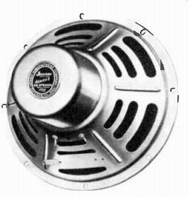
------------- A speaker converts alternating current and voltage into
sound due to electromagnetic action. Courtesy Jensen Mfg. Co.
VARIATION IN DIRECTION AND AMOUNT OF INDUCED VOLTAGE
To simplify the explanation and provide more details of this all important action, in Figures 7, 8, 9, and 10, the front half of the generator of Figure 6 has been removed. The remaining cross section views indicate only the rear halves of the magnet poles and the rear half of the loop.
In Figure 6, the loop makes a quarter turn in moving from Position 0 to Position 3. From left to right, two intermediate positions of this rotation are shown in Figure 7. At each position, the induced voltage and direction of the resultant current, if any, are shown with a dot and a cross mark. As explained before, the dot in the center of the conductor cross-section represents current out toward you, the cross mark represents current in away from you and the curved arrows show the direction of rotation.
As the loop turns from Position 0 shown at the left in Figure 7 to Position 3 shown at the right, it will cut more and more lines as the angle of cutting increases.
The induction increases steadily until the maximum is reached.
The current produced by this voltage also increases steadily and is in a direction in on side A and out on side B. Going back to Figure 6, since side A is connected to ring and brush D, and side B is connected to ring and brush C, the external resistor receives increasing "+" voltage from brush D or an increasing "- " voltage from brush C. Thus, in the Position 3 at the right in Figure 7, the loop generates maximum "+" at brush D or maximum "" at brush C. In turning from Position 3 to Position 6 of Figure 6, the loop makes the second quarter turn which is shown in greater detail in Figure 8. Here the extreme left position is the same as the extreme right position of Figure 7 in which the preceding quarter turn was completed. Since side A still moves left past the N pole, and side B moves right past the S pole, the directions of induced voltages and current remain the same. However, the angle of cut ting is decreasing and so, the induced voltages and resultant current also decrease steadily. In Position 6, no magnetic lines are being cut, therefore the voltage and current drop to zero. Notice that at the beginning of the turn in Figure 7, side A was on the right and B on the left, but now B is on the right and A is on the left.
In turning from Position 6 to 9 of Figure 6, the loop makes the third quarter turn shown in Figure 9. Side A now moves down and right past the S pole, and side B moves up and left past the N pole. As the angle of cutting increases voltage is induced again, but in the opposite direction. Side A is now " -", and B is " + ". The angle of cutting increases steadily as the loop turns until there is maximum induction in Position 9 at the extreme right in Figure 9.
Notice that the corresponding condition in Position 9 of Figure 6 shows " + " at brush C and " - " at brush D. Again the external circuit has maximum current but in the direction opposite to that for Position 3.
In the final quarter turn, as the loop rotates from Position 9 of Figure 6 around to Position 12, conditions are as shown in Figure 10. Side A still moves right past the S pole and B moves left past the N pole, therefore the direction of induced voltages and current are the same as for Figure 9. However, now the angle of cutting is decreasing and so induced voltages and current decrease steadily. In Position 12, no magnetic lines are cut and the voltage and current drop to zero.
The end of the fourth quarter turn brings the loop back to where it started in Figure 7, Position 0, so the events of Figures 7, 8, 9, and 10 will repeat during each succeeding revolution.
ALTERNATING CURRENT
When the loop is turned continuously in the same direction, the induced voltages and resultant current will reverse direction in each side during each complete turn. Since sides A and B connect to the external resistor through the rings and brushes, as the loop is turned, the current in the circuit is first in one direction and then in the other. Starting from the position of zero induction, for the first two quarters of a turn of the loop, brush C is "-" and D "+", and the current is in the other direction. This periodic change of direction of electron flow is called alternating current (a-c) and generators that produce alternating current are called alternators.
SINE CURVE
During each rotation of the coil there are two positions in which the lines of magnetic force are cut at the greatest rate, and two positions in which the lines are not cut at all, therefore the maximum and minimum induced voltages both occur twice during each revolution of the loop.
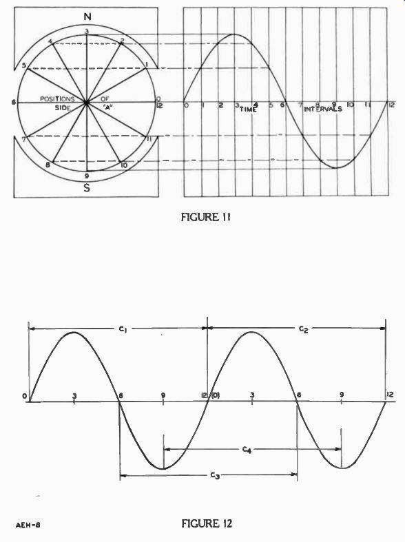
With the loop revolving at a uniform speed in a uniform magnetic field, at any intermediate point between the minimum and maximum, the induced voltage is always some fractional part of the maximum. This intermediate or instantaneous value depends on the angle of cutting the magnetic field in that particular position. The minimum, intermediate, and maximum induced voltages for an entire revolution can be shown quite nicely by what is called a sine curve like that at the right in Figure 11.
To simplify the explanation and provide additional details regarding the action of the simple generator of Figure 6, only the mag net poles and rear end of the loop are shown in Figures 7, 8, 9, and 10. As the induction is the same in sides A and B of the loop, still further simplification can be made. By omitting side B, all the positions of the loop indicated in Figures 7, 8, 9, and 10 are combined in the diagram at the left in Figure 11 and side A has the same position numbers shown in the previous Figures.
To visualize the induction with in a loop, a graph is constructed by first extending to the right a line connecting Positions 6 and 0. Since this line marks the Positions of side A when it is cut ting no magnetic lines, it is the zero voltage reference line. With the loop turning at a uniform speed, it requires equal intervals of time for it to move from each position to the next. Therefore, the horizontal line is divided into 12 equal spaces to represent equal time intervals between the different positions of the loop. Vertical lines then are drawn through these division points and labeled "0" to "12" to correspond with the time intervals for a complete turn or revolution of the loop.
The next step is to plot the voltages for each of the 12 positions.
When side A is in Position "0" it cuts no lines, no voltage is induced, and the line joining this position and the "0" time line of the graph shows this condition. _ When side A is in Position 1 with respect to the magnetic field, it is moving through and cutting magnetic lines, therefore a voltage is induced. The value of this voltage is plotted by drawing a horizontal line from Position 1 to cross or intersect the vertical line for the time interval 1. The same procedure is followed to plot the voltages for the balance of the positions. In each case a horizontal line is drawn from each position of side A to intersect the correspondingly marked time interval line. Connecting these points of intersection with a curved line, provides a graph of the voltages induced in side A for all points of the rotation. The direction of the curve, above or below the horizontal zero voltage line, indicates whether the induced voltage, and the current it will produce, is " +" or " -", and the distance of the curve above or below the zero voltage line indicates the instantaneous value of the voltage induced. Therefore the curve can be used to determine the induced voltage in positions between those plotted.
At positions 3 and 9 of Figure 11, the MAXIMUM values are reached. Sometimes these are called PEAK values. Both are measured from the horizontal line to the highest value, hence, at position 3 a positive maximum occurs, while at position 9 a negative maximum occurs.
Also, the sine curve of Figure 11 summarizes the inductive actions during a complete revolution of the loop. As side A moves past the N pole all the voltages between Positions 0 and 6 are above the horizontal line or " ". These values increase from zero in Position 0 to maximum in Position 3, then back to zero in Position 6. As side A moves from Position 6 past the S pole all the voltages between Position 6 and 12 are below the horizontal line or "-". These values increase from zero in Position 6 to a maximum in Position 9, back to zero in Position 12, and the same series of voltage variations repeats.
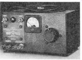
------------- Alternating current at 60 cycles rated at 115 volts is used
by this variable power supply. Courtesy General Radio Company.
CYCLES AND ALTERNATIONS
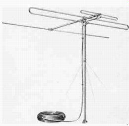
------------- Popular type of TV antenna which picks-up high frequency
alternating current from TV stations. Courtesy American Phenolic Corp.
The word cycle is used often in the study of alternating current and electronic principles, and should be understood clearly. A cycle is a series of events which takes place over and over again at regular time intervals. Holidays, days of the week, months or seasons of the year, are good examples of events that occur in cycles. For example, the change of seasons depends on the position of the earth in its orbit around the sun. The earth makes a complete revolution around the sun once a year. During the year spring, summer, autumn, and winter appear in turn. Then as the earth starts another revolution around the sun, the entire cycle of seasons repeats.
When a revolving object produces different conditions in different parts of each revolution, those conditions are repeated in recurring cycles as the revolutions continue. This general statement also applies to revolving loops and particularly to the variations in induced voltages in different parts of each revolution.
All the changes in the direction and value of induced voltage that occur during one complete turn are considered to be parts of one cycle. As the loop continues to rotate, the same conditions are repeated in recurring cycles. The sine curve of Figure 11 shows one cycle of voltage changes that occur in side A during one revolution of the loop. If the factors affecting the induced voltage do not change, the curves of all succeeding will be exactly the same.
Thus, in Figure 12 with C1 as the first cycle, the second cycle would be C. We could have rotated the generator of Figure 6 in the opposite direction, then the cycle would appear as C3 where the first alternation is negative while the second is positive. In fact, we could have started the rotation from any position to generate one cycle. For instance, starting from position 9 in Figure 11, we could generate the wave-form C4 in Figure 12. As long as one complete revolution is performed no matter what the starting position, upon returning to that position one complete cycle is generated.
Since one cycle is completed during each revolution, the time required for each cycle will depend on the speed at which the loop is turned. For example, if the loop is rotated at a speed of 3,600 revolutions per minute, which is equivalent to 60 revolutions per second, it will produce 60 cycles per second (60 cps). The number of cycles that occur in a given time is called the frequency (f). Thus, if the loop makes 60 revolutions per second, the frequency will be 60 cycles per sec gild.
However, since the second is used as the standard unit of time in electronics, frequency often is expressed simply as a number of cycles, and per second is under stood. For example, ordinary 110 volt a-c used for house lighting normally is expressed as having a frequency of "60 cycles" rather than "60 cycles per second". Figure 11 shows how each cycle is made up of two like parts, one above and the other below the horizontal zero voltage line. Each part is called an alternation. The one above the zero voltage is the positive alternation and the one below the line is the negative alternation. Since a complete cycle is made up of two alternations, the 60 cycle a-c mentioned has 2 times 60 or 120 alternations per second.
A SIMPLE ALTERNATOR
Although it has been common practice to call any machine, that generates electric energy by electromagnetic induction, a genera tor, a machine that develops an a-c voltage is more frequently called an alternator.
Because it supplies an alternating current that changes in magnitude and direction during each complete revolution of the coil, the machine of Figure 6 is a simple alternator. Instead of permanent magnets, in most commercial alternators, the magnetic field is produced by electromagnets. And in place of a single loop, many interconnected loops are mounted uniformly around the shaft to obtain increased induction and output. That part of the alternator which remains stationary is called the stator and the moving part is the rotor.
As shown in Figure 6 slip rings and brushes are employed to connect the rotor to the external circuit. However, the a-c output from large, commercial service alternators generally is of high voltage and current, and thus would require heavy, well insulated slip rings and brushes.
Therefore, the rings and brushes are employed to carry current from a low-voltage d-c generator to the electromagnets that are mounted on the rotor while the high voltage a-c output is taken from the stator windings.
The simple alternator described in this lesson uses a moving wire in a magnetic field to generate an a-c voltage. In contrast, a trans former has stationary wires while the magnetic field alternates or changes. While it generates no voltage, the transformer does convert the a-c from some central source to the desired voltage for use in electron tube equipment.
How the transformer is constructed to accomplish this con version is described in the following lesson.
IMPORTANT DEFINITIONS
ALTERNATION-[awl ter NAY sh'n]--One-half of a cycle consisting of the complete rise and fall of an alternating voltage or current in one direction.
ALTERNATING CURRENT- (a-c)--A current which changes its direction periodically.
ALTERNATOR-[AWL ter nay ter]-An alternating current generator.
BRUSHES-Formed pieces of carbon or graphite that provide a sliding contact between the collectors or commutators and the external circuit.
COLLECTORS-The circular contacts used on an alternator which are connected to the rotating loops. Often called slip rings.
CYCLE-[SIGH k'l]-The complete set of values through which an alternating voltage or current passes successively.
FREQUENCY (f)-[FREE kw'n si]--The number of cycles of alternating voltage or current which occur in one second.
GENERATOR-[JEN er ay ter]-A machine for converting mechanical energy into electric energy, by causing a series of interconnected coils of wire to cut or be cut by a strong magnetic field.
ROTOR-[ROH ter]--The rotating member of a generator.
SINE CURVE-[sighn kerv]-The graph of an alternating voltage or current which shows the instantaneous values for each instant of time.
STATOR-[STAY ter]-The stationary coils of a generator.
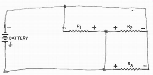
WORK DIAGRAM
By means of pencil lines, connect these resistors in parallel across the battery so that the correct polarities are indicated.
------------
When you have finished, check with the answer on the back of the fold-out sheet.
STUDENT NOTES
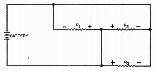
WORK DIAGRAM SOLUTION
------------
------------- FIGURE 11
FIGURE 12
----------------
----------------
FROM OUR Director’s NOTEBOOK
THE LEADER
The man who is worthy of being a leader of men will nevercom plain of the stupidity of his helpers, of the ingratitude of mankind nor of the in appreciation of the public. These things are all a part of the great game of life, and to meet them and not go down be fore them in discouragement and defeat is the final proof of power.
-Elbert Hubbard.
Your for success,
-DIRECTOR