AMAZON multi-meters discounts AMAZON oscilloscope discounts
Lessons AEH -9A
ELECTRONS MEASURE STRESS
As the air blast changes within a modern wind tunnel, several hundred meter needles shift on the external control panels. Wired to an electronic gauge about the size of a postage stamp, each meter indicates the strain produced at some particular point on the structure being tested.
Many types of electronic gauges and detecting devices have been developed to pre vent accidents and injuries. Phototube equipment stops punch presses and power shears when an operator's hand is in the path of the punch or moving blades. In mines, electronic equipment can be connected to close safety doors, operate traffic lights, turn on blowers, or sound alarms when the gas con tent in the air reaches dangerous levels.
A stability gauge stops a large crane automatically if the boom is extended too far or is loaded too heavily and there is danger of the crane overturning. Other electronic indicators give advance warning of impending floods, guard industrial plants against night intruders, or detect fire, smoke, and dangerous gas.
TRANSFORMERS
Contents:
Self Induction in a Straight Wire Self Induction in a Coil How Inductance Can Be Varied Inductance Units Energy Stored in a Magnetic Field Induction Using Electromagnets Mutual Induction Coupling and Flux Linkage Transformer Action by Induction Transformer Cores Transformer Losses Eddy Currents Step-up and Step-down Transformers Transformer Energy Coupling Symbols
"A person should never be ashamed of possessing but little knowledge. But a person should be ashamed if he fails to add to his knowledge whenever he can and especially so when he fails to make use of it for himself and his fellow men.
-Arthur Brisbane
TRANSFORMERS
Regardless of its size or use, practically every modern piece of electronic equipment today uses transformers. Most of this apparatus has a transformer in the power supply, but this isn't the only place where transformers are useful.
Whenever one section of the apparatus supplies a voltage and current to another, if this combination isn't correct for best operation, a transformer is inserted between the two. That is, when the voltage is too low the transformer increases the voltage and reduces the current, or where a large current is needed the transformer increases the current but reduces the voltage.
For this operation the trans former makes use of several important factors described in the last two lessons. One of these is that a voltage can be induced into a wire or coil whenever it cuts or is cut by a magnetic field. In the last lesson a coil of wire or loop was moved in a magnetic field. In a transformer, however, the coil is held still and the magnetic field is moved. The second important factor used in transformers is that an alternating current produces a moving field.
To be an efficient technician, you must know how these factors are used in a transformer and how to determine which trans former is needed for a particular application. Therefore, in this les son we describe the basic features of all transformers by showing how they apply to power trans formers such as the one found in Figure 15.
SELF INDUCTION IN A STRAIGHT WIRE
As you know, electron flow through a wire produces a magnetic field. Let's pass a d-c current through a wire shown as a cross-section in Figure 1. As long as the electric circuit is not complete, Figure 1A shows no magnetic field about the wire. however, the instant the circuit is "closed", a current is established and the conditions in Figure 1B exist. The magnetic field has just begun to build up, and starting from its center, the magnetic lines are all inside the wire.
An instant later, as shown in Figure 1C, the field has built up further, and there are more magnetic lines which extend out around the outside of the wire.
Each of these lines started at the center and cut through all or part of the wire to reach its present position. In Figure 1D, the current has reached its normal value and the magnetic field has still more lines, most of which have cut through the wire.
If the electron flow in the wire is toward you, or "out" from the paper, by the Left Thumb Rule the magnetic lines will be around it in a clockwise direction.
Figure 2A is the cross section shown in Figure 1A with several additions. The outer circle is the entire solid wire, while the small inner circles are drawn, for purposes of our explanation, to rep resent the solid wire as being made up of many smaller wires
or strands which are labeled A, B, C, etc. Electrons are flowing in each of these strands in the same direction as shown for the wire in Figure IA. Although part of one solid wire insofar as action is concerned, each of these strands can be considered as separate physical wires, therefore A and B are drawn as separated in Figure 2B. Since A and B have electrons flowing through them, then each has a magnetic field about it.
The magnetic fields about A and B are shown in a clockwise direction as it expands from the center of each strand, just as for Figure 1A. As the magnetic field of A passes outside of strand A, it nears strand B. Since the magnetic field of A resists being bro ken, it tends to wrap itself about strand B as shown by the dotted lines, but finally, this expanding field cuts strand B and induces a voltage in it. Using the dashed lines as the magnetic field about strand B with the Left Thumb Rule, the voltage induced in the complete circuit is of such a polarity that current is INTO the paper. This is opposite to the source voltage causing current OUT OF the paper in strand B. A similar opposing current is generated in strand A by the expanding field of B. Thus, since the voltages in each strand op pose each other the effective voltage in each of them is the difference between the original voltage and the induced voltage. Now by recombining all the strands as one wire, the voltage induced in the wire by the expanding field reduces the applied voltage so that the resulting voltage is lower. Hence there is less current in the circuit.
The opposite voltage is called a counter electromotive force (CEMF) or counter emf because it opposes the voltage causing the action.
Inducing voltage into the current conductor is called self induction, and like all forms of induction it occurs only while the magnetic field is changing. Figure 1D, has the full magnetic field, but since no further change occurs, there is no further induction, and the counter emf dies out. Although this complete action takes place very rapidly, in a small fraction of a second, the self induction does prevent the current from rising instantly to its full value.
In Figure lE the conditions are the same as at "D", at the instant the circuit is opened. As the current dies out, the magnetic field collapses as shown at "F", "G", and "H", which is just opposite to the way it built up at "A", "B", and "C". Here again there is self induction but, since the magnetic lines are now collapsing, the direction of the induced voltage will be "out" from the paper or opposite to what it was while the field was building up. The self induction which opposed the increase of electron flow before, now has reversed its direction and will attempt to maintain the original current for a brief instant.
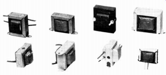
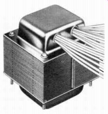
----------------- Various types of small transformers used in radios. Courtesy
General Electric Co.
SELF INDUCTION IN A COIL
Self induction in a coil of wire is much greater than in a straight wire of the same length, because the magnetic field around each turn cuts not only the turn that sets it up, but also the turns close to it. To show this action, part of a coil of wire is cut away in Figure 3. With the direction of the current as indicated by the arrows, the magnetic field is exactly like the one described in the les son on electromagnets. The important thing to notice in the cut away part of the coil is that the magnetic lines set up around the first turn cut the next turn also.
As this overlapping of magnetic lines occurs between all the turns, the induced voltage will be much greater than in a straight wire, and the amount of self induction in a coil depends on the ampere-turns and the reluctance of the magnetic circuit. That is, the stronger the magnetic field a conductor produces, the greater the self induction.
The effects of self induction are summarized by the following statements:
1. Whenever a circuit current increases, the induced counter emf opposes the change of current and prevents it from rising instantly to its steady value.
2. Whenever a circuit current decreases, the induced emf is in a direction to oppose the change and tends to maintain the current.
Notice particularly, induction occurs only while the current is changing and the counter emf is always in a direction to oppose the change. With a uniform or steady current, there is no induction and, therefore, no counter emf.
HOW INDUCTANCE CAN BE VARIED
When there is a variation of current in a circuit, the magnetic flux varies also, expanding as the current increases and contracting as the current decreases. In moving, the magnetic lines of force cut any conductor which is within their range and induce a voltage that is always in such a direction as to oppose the current change.
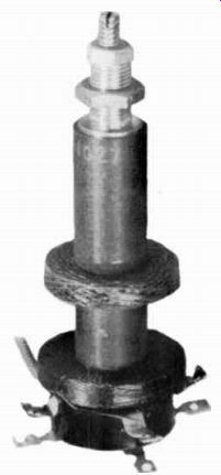
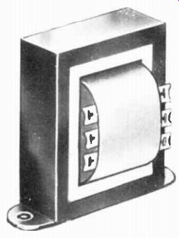
-------------- The inductance of this transformer can be varied by moving
a metallic core in or out by means of the screw adjustment. Courtesy Meissner
Mfg. Div., Maguire Industries Inc.
Known as inductance, the ability to produce a voltage by electromagnetic induction when the current changes, is a property possessed by a circuit because of its physical arrangement. Thus, a conductor has inductance whether or not a current is in it.
The inductance of a circuit depends on the number of magnetic lines which cut the conductor for each ampere change in current.
Anything that increases the number of flux lines cutting the conductor for each ampere change in current increases the inductance.
Hence, a conductor wound into a coil as shown in Figure 3 has a greater inductance than a straight wire, because the flux developed by one turn of wire in the coil also cuts practically every other turn as it expands or contracts.
For the same reason, an iron core placed within the coil increases the inductance, because the lower reluctance of the magnetic circuit permits a greater flux and there fore, more lines cut the conductor as the current changes. Since a coil of wire possesses the property of inductance it is called an inductor.
Induction is the result of electromagnetic action in a circuit containing inductance, and as a general definition: self inductance is the ability of a circuit to produce a voltage within itself by induction when the current in it changes.
INDUCTANCE UNITS
As for all other electric proper ties, there is a unit of measure for inductance. It is the henry (h), named for the American physicist Joseph Henry (1797-1878) who, in 1831, discovered the voltage caused by self induction. By definition, THE HENRY IS THE INDUCTANCE WHICH INDUCES A POTENTIAL DIFFERENCE OF ONE VOLT WHEN THE CURRENT IS CHANGING AT THE RATE OF ONE AMPERE PER SECOND. The henry is a large unit, consequently for many practical applications, two smaller units are employed. One is the millihenry (mh), equal to one one-thousandth (, of a henry, and the other is the microhenry (p1), equal to one one-millionth ( ) of a henry.
The schematic symbol for an inductor is shown in Figure 4.
This symbol remains the same regardless of the type of winding or the number of turns involved. However, when an iron core is used, it is frequently indicated by adding parallel lines, as shown in Figure 5. The letter "L" along with subscripts 1, 2, 3, 4, etc. are added for identification purposes.
ENERGY STORED IN A MAGNETIC FIELD
It is a well established fact that matter cannot set itself in motion, and that energy for its movement must be supplied from some out side source. This truth is illustrated by the fact that a table cannot push itself across the floor.
Only when a person supplies the necessary energy does the table move, thus the energy for its movement comes from outside the table. So in an electric circuit, a current cannot set itself in motion, but must be produced as a result of the energy supplied by an electromotive force.
The current produces a magnetic field around the wire, and while the flux is increasing, the counter emf of self induction op poses the current and prevents it from instantly reaching its final value as determined by the applied voltage and circuit resistance. To overcome this counter emf, work must be done. Since it is not destroyed, the energy of the changing current is stored in the magnetic field around the wire or coil.
After the increasing magnetic field reaches its peak strength, no further counter emf is produced and no further energy must be expended to maintain the field.
When the electric circuit is opened and the current stops, the collapsing magnetic field returns the stored energy to the circuit in the form of the induced voltage that tends to maintain the current.

------------- Used in industrial electronics for induction heating,
these coils are made of heavy wire for the purpose of carrying a large current.
Courtesy Lepel High Frequency laboratories, Inc.
INDUCTION USING ELECTROMAGNETS
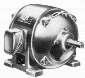
------------ The interactions between the magnetic fields of stationary
and pivoted coils cause this motor to rotate. Courtesy Louis Allis Co.
In the lesson on electromagnets, it was shown that the magnetic lines of force, set up around a current carrying conductor, are exactly the same as those produced by a permanent magnet.
Also, with current in a coil of wire, it sets up a surrounding magnetic field like that of a permanent bar magnet. Thus, by arranging the wire or conductor properly, an electric current will produce a magnetic field which can replace the field of a permanent magnet.
There are several practical reasons why, in many cases, an electromagnet is preferable to a permanent magnet. Thinking of a coil of wire, by using the proper number of ampere turns, a magnetic field of almost any required strength can be produced, and so by regulating the current in the coil, the strength of the magnetic field can be varied as desired. In fact, by opening the circuit, there is no current in the coil and the magnetic field dies out completely. Because it is controllable, the electromagnet has many applications for which the permanent magnet is not suitable.
Induction was explained in the lesson on magnetism by means of a permanent magnet and a coil of wire. The same action is illustrated in Figure 6 but the permanent magnet is replaced by an electromagnet, consisting of a coil of wire wound on an iron core and connected to two dry cells. A second coil is wound on a paste board tube large enough to slip over the electromagnet. The ends of this second coil are connected to a sensitive zero center meter.
Pushing the electromagnet into the center of the coil of wire makes the meter pointer swing in one direction. Pulling the electro magnet out swings the pointer the opposite direction. This action, of course, merely shows that a voltage can be induced in a conductor by cutting the magnetic field of an electromagnet and the induction is exactly the same as with a permanent magnet.
Notice, there are two distinct and separate electric circuits, one consists of the battery and a coil of wire for the electromagnet, while the other circuit is made up of a coil of wire and a meter.
Both coils are placed so that the magnetic field set up by one will cut through the other.
The coil connected to the battery or source of electricity is called the primary because the first action of setting up the magnetic field, occurs around this coil, The other coil is called the secondary because the second action or the induction of a voltage, takes place when it is cut by the magnetic field of the primary.
MUTUAL INDUCTION
A voltage can be induced in a wire or coil by a change of current in an adjacent wire or coil.
This electromagnetic induction, due to the variable flux caused by one conductor cutting the other conductors, is called mutual induction. To illustrate the mutual induction between coils, the primary and secondary circuits of Figure 7 are electrically separate, although the coils are wound on the same core.
The primary circuit consists of the primary winding, the battery, and the switch, while the secondary circuit consists of the secondary winding and the meter. So long as the switch is open, nothing happens. No current is in the circuit, therefore no magnetic lines are set up around the primary, and with no magnetic lines no induction occurs in the secondary.
When the switch is closed, the primary current produces a magnetic field, which starts in the iron and moves out, as pictured with the light arrowed lines. During this interval the magnetic lines cut through the secondary and induce a voltage in it.
Since the primary coil has a fixed resistance, the voltage of the battery can force only a certain current through it. The strength or magnitude of the magnetic field depends on the ampere-turns of the primary. For the short time it takes the magnetic field to build up, the lines will cut through the secondary coil, but when the field reaches its full strength, the lines no longer move out, no longer cut through the secondary, and there fore, induce no further voltage.
For this reason, the meter pointer swings when the switch in the primary circuit is first closed, then drops back to zero.
When the primary switch is opened, the current drops to zero and the magnetic lines fall back toward the iron core or collapse, and thus again cut through the secondary, but in the opposite direction to when the switch was closed. Therefore, the pointer de- fleets momentarily in the opposite direction.
By closing and opening the primary circuit, thus building up and collapsing the magnetic field, the lines cut through the secondary. If the primary switch is opened and closed rapidly enough, to maintain a continuous change of magnetic flux, a potential difference will be induced in the secondary all the time, but it will be of one polarity when the switch is closed and of the opposite polarity when the switch is opened. As the direction of the current caused by this induced voltage re verses direction periodically it is an alternating current.
An important thing to remember is that there must be motion between the magnetic lines and the secondary. A varying primary current causes a changing magnetic field, and a secondary placed in the field will be cut by the magnetic lines as they move away from and return toward the primary carrying this current.
The effect of mutual induction between two wires is the same as that between two coils. To illustrate this action, the two wires shown in Figure 8 are electrically insulated from each other but are placed fairly close together. In Figure 8A, with no current in wire 1 there is no magnetic field around either wire. But in Figure 8B, with a current in wire 1 a magnetic field extends around it and beyond wire 2, and the only way these lines can extend beyond wire 2 is by cutting through it.
With any fixed current in the wire, the field builds up and spreads out to some certain distance and then remains constant.
A voltage is induced while the magnetic field is building up and cutting wire 2, because there is a relative motion between the field and the wire during the time interval the field is spreading out.
However, when the field becomes constant, there is no further motion, and the inductive action ceases.
When the circuit of wire 1 is opened and the current stops, the magnetic field collapses and falls back in toward wire 1. Thus, the field again cuts through wire 2, but in the opposite direction to when it was spreading out. Again, a voltage is induced, but of opposite polarity.
Just as self inductance is the ability of a wire to induce a voltage within itself, mutual inductance (M) is the ability of one conductor or coil to induce a voltage in another. Do not confuse mutual induction with mutual inductance. Mutual induction is the ACT of inducing a voltage in one coil or conductor due to a changing current in another. Mutual inductance is the ABILITY to in duce the voltage and this exists regardless of the current in the circuit.
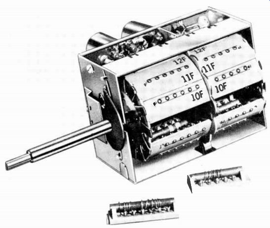
------------- A television receiver tuner with two of the twenty-four
coil strips removed. Courtesy Standard Coil Products Co.
COUPLING AND FLUX LINKAGE
When two coils are placed so that all or part of the magnetic field of one passes or cuts through the conductors of the other, electric energy is transferred from one coil to the other by the mutual induction between them. Because the two circuits are coupled or linked by the changing magnetic lines of force, often mutual induction is referred to as inductive coupling. The closer the coils, the greater the number of lines of force due to the primary current, that link with the turns of the secondary, and the closer or tighter the coupling is said to be.
The product of the magnetic lines of force and the number of turns in the coil through which they pass is called flux linkage, In most cases, the position of the coil with respect to the magnetic field determines the actual flux linkage. If the coil is close to a magnetic field so that most of the flux lines thread through the turns, the flux linkage is high, but if the coil is at a distance from the magnetic field, very few lines link with the coil, and the flux linkage is low.
TRANSFORMER ACTION BY INDUCTION
The arrangement of two fixed coils wound on a core, as shown in Figure 7, is known as a trans former. A transformer is an electric device, without mechanically moving parts, for transferring electric energy from one or more circuits to one or more other circuits by electromagnetic induction.
A very important point to re member is that although a battery is shown, a transformer will not operate with a steady current in the primary. For electromagnetic induction to occur, there must be a changing magnetic field such as is produced when the switch of Figure 7 is closed or opened. For an instant after the closing or opening of the switch, the magnetic field is building up or dying out and a voltage is induced into the secondary. At all other times, the magnetic field is stationary and no induction can occur.
Thus for the transformer to operate continuously, the primary must be connected either to an intermittent source of current or to some source of alternating current. As explained in an earlier lesson, an alternating current continuously changes in value and periodically reverses its direction, therefore the magnetic field around a primary carrying an alternating current is constantly building up and dying down, first in one direction and then in the other. These changes of the field mean that the magnetic lines continually cut through the secondary and induce a voltage in it.
TRANSFORMER CORES
Frequently transformer cores are formed into a square or rectangular "loop" to provide a complete, closed path or circuit for the lines of magnetic flux. A core with this shape is shown in Figure 9. Here, a solid block of steel with a square hole in the center has the primary coil wound around one "leg" and the secondary on the other. Produced by the current in the primary, the flux is carried almost entirely by the core, and thus passes through the secondary winding to induce the desired emf.
In addition to a magnetic circuit, the solid metal core forms a path for electric currents which are induced in it by the flux. To reduce these currents which cause heat loss, practical metal cores are made of a large number of thin sheets called laminations which are bolted together tightly.
The laminations are cut or stamped from thin sheets of steel which generally range from 6 to 25 thousandths of an inch in thickness. The steel sheets used have rust scale on their surfaces, and when the core is formed, the scale insulates the adjacent laminations and thus prevents currents from passing from one to the next, and so loss due to an induced current is reduced to a low value.
To avoid the difficulty of threading the turns of coil wire through the central opening of a solid core like that of Figure 9, the laminations are shaped so that two pieces are required to form a rectangle.
By this plan, the coils can be wound without a core and after they are completed, the laminations can be placed in their central opening.
One type of lamination, shown in Figure 10A, has an L shape.
With the finished coils in proper position, one L lamination is placed in the center of each coil.
Additional laminations are then stacked in the coils, to form the completed core, shown in Figure 10B. Usually one side of the L is longer than the other and they are stacked alternately to provide the indicated staggered joint between adjacent rectangles. Trans formers assembled in this way are known as CORE types.
------------- Notice the laminations of this shell type trans former.
The core is laminated to reduce the power loss due to eddy currents. Courtesy
Standard Transformer Corp.
Another common transformer core known as the SHELL type, is made of "E" and "I" shaped laminations as shown in Figure 11A. This arrangement forms two rectangles and all of the coils are made to fit on the center bar of the E. As explained for Figure 10, the laminations are stacked in the center opening of the finished coils to form the assembly of Figure 11B.
Laminations of this shape can be stacked in either of two ways.
First, adjacent "E's" are inserted from opposite ends of the coil and each layer completed with an "I". This forms the staggered joints indicated in Figure 11B. Second, all the E's can be inserted from the same end of the coils to provide the core illustrated in Figure 12. Then an equal number of I laminations are placed across the open end of the E's to complete the core.
Figures 10B and 11B are "semi schematic" insofar as the windings are concerned, in order to show the core construction. The actual arrangement used in a practical transformer with shell type core is illustrated by the cut away view in Figure 12. Here, the "I" stack is removed to show that both windings consist of a relatively large number of turns.
The primary is wound around the entire center leg of the "E" stack and the secondary is wound around the primary, while a layer of insulation separates the two windings. When the windings and core have been assembled, the en tire unit is clamped together with bolts extending through the stacks as shown in Figure 13.
Possibly you have heard a buzzing or humming sound around a radio or television set. This may be caused by the vibration of laminations which have worked loose. Therefore, this noise is a servicing clue to the technician to tighten the bolts.
TRANSFORMER LOSSES
In general, losses of energy in a transformer are the result of core losses, copper losses, and stray losses of various types.
Existing only in transformers which employ cores of magnetic material, core losses are of two kinds, hysteresis loss, and eddy current loss.
Copper losses are losses of energy in the form of heat produced due to the currents in the conductors of the transformer windings. They are minimized by employing large diameter conductors to reduce the resistance per unit length of the wires.
In power supply transformers HYSTERESIS forms approximately 3/4 ths of the core loss. The term "hysteresis" describes a slight lagging of the flux density which occurs when the alternating magnetizing force, due to the primary a-c, sets up the alternating flux in the iron core. This lag is due to the tendency of the iron to oppose a change in magnetism. Thus, whenever the flux density is being increased, the magnetizing force must be a little greater than it would if hysteresis were not present.
Also, after the magnetizing force has reduced to zero at the end of an alternation, a certain magnetization remains in the core, and can be decreased to zero only by the application of magnetizing force in the opposite direction. In the form of these extra magnetizing forces during each cycle, a certain percentage of the total energy supplied is used to overcome the hysteresis effect, and this energy is lost insofar as the transformer action is concerned:
EDDY CURRENTS
Referring to Figure 7 when the switch is closed the direction of electron flow in the primary is from top to bottom on the near or visible side of the coil through the positive of the battery and back to its negative terminal. When the switch is closed, the primary current causes an expanding magnetic field which starts at the center of the core and moves outward in all directions. Cutting the coil wire as they expand, the magnetic lines induce a voltage which opposes the current and prevents it from rising instantly to its full value.
Wound on the same core as the primary, the expanding lines cut the wire of the secondary coil and induce a voltage in it. This induced voltage is in the same direction as the counter emf induced in the primary, but with no other voltage source, if its circuit is closed, the induced secondary voltage will cause a current. This action was mentioned previously to explain the kick of the meter pointer when the primary switch is closed and opened. With the meter removed and the coil ends connected directly, the action will remain the same.
Suppose the coil of wire is replaced by a copper tube with no external circuit, the induced voltage will cause current to circulate around the tube exactly the same as around each turn of a coil. Notice here, the direction of this current is parallel to that in the turns of wire in a coil but at right angles to the axis of the core and the magnetic lines.
Going a little further, the iron core is an electric conductor therefore, any change of the magnetic fields which induces a voltage in the coils will induce a similar voltage in the core also. Like the cop per tube, the core can be considered as a closed circuit and thus, the induced voltage will cause circulating current in it. This circulating current in the core will set up a magnetic field of its own which always will be in a direction to oppose the changes of current.
However, more important is the fact that the currents set up in the core will produce consider-able heat, which is a waste of energy, impairing the effectiveness of the transformer. Currents produced in a piece of metal in this matter are called eddy currents.
--------------- A type of transformer having solder lugs for connection.
Courtesy Standard Transformer Corp.
By using a laminated core, the eddy currents are reduced with out increasing the reluctance of the magnetic circuit. The laminations lie in the same direction as the flux, therefore, the insulating surfaces are directly across the path of the eddy currents. The resulting eddy current reduction greatly improves the operation of the transformer.
All of these losses make the typical transformer hot when operating under full load. In fact, how much heat the insulation can take without breaking down determines the power limitations of the transformer. Therefore, al though most transformers are too hot to hold a hand on withcom fort, there should be no odor of burning insulation or varnish or signs of discoloration or smoke.
Any one of these would indicate to the technician that the trans former is overloaded, and he would investigate to find out why.
STEP-UP AND STEP-DOWN TRANSFORMERS
Not only is a transformer employed to transfer electric energy from one circuit to another, as we mentioned earlier, it also raises or lowers the voltage to meet certain operating requirements. For example, in practically all alternating current power lines, the voltage is "stepped up" at the power house, carried long distances, and then "stepped down" at the place where it is used. Also, in practically all electronic apparatus, designed to operate from 110-volt a-c lighting circuits, transformers are used to lower the voltage for some circuits and raise it for others.
The induced secondary voltage is affected by four factors: the speed of cutting the lines of force, the length of the conductor, the strength of the flux, and the angle of cutting. The speed cannot be changed in a transformer, be cause it is controlled by the rate at which the magnetic field of the primary builds up or collapses.
When the primary circuit is closed and opened, the change in magnetic flux takes place as rapidly as possible. Also, the strength of the field can be ruled out because it is determined by the core material and the ampere-turns of the primary coil which is made up of a specific number of turns and with a certain resistance, so that it carries a definite current. The angle of cutting cannot be changed, since the coils already are arranged permanently on the core.
Only the length factor is left but it can be put to good use for the purpose. Suppose the secondary is wound with twice as many turns as the primary. Then the same number of magnetic lines, moving at the same speed, and cutting at the same angle, but cutting twice the length of wire, produces twice the voltage in the secondary. The reverse also is true. If the secondary is wound with half as many turns as the primary, then the same number of magnetic lines, moving at the same speed and cutting at the same angle but cutting half the length of wire, produces half the voltage in the secondary.
These two examples illustrate the definite relationship between the number of turns and the voltage of each winding. As a general rule, this relation may be stated as: IN A TRANSFORMER, THE SECONDARY VOLTAGE DIVIDED BY THAT OF THE PRIMARY IS THE SAME AS THE NUMBER OF TURNS IN THE SECONDARY DIVIDED BY THOSE IN THE PRIMARY. That is, in an abbreviated form: E. T. E„ T,, (I) where E. and E„ are the secondary and primary voltages, and T„ and T„ are the secondary and primary turns.
If the primary turns and voltage are known and it is desired to determine the number of turns required for a given secondary voltage, the expression may be re written:
T, - E,, (la)
and the known values substituted for the letters. In words, the above says: "Multiply the secondary voltage by the number of turns in the primary and divide this number by the voltage of the primary to get the number of turns in the secondary." To illustrate the use of this equation, assume that the primary of Figure 7 has 30 turns and operates at 3 volts. How many secondary turns are required to produce 300 volts? T„=30 times 300 divided by 3 or 3,000 turns As mentioned earlier, trans formers may be used to raise or lower the voltage. One with more turns of wire in the secondary than in the primary like Figure 10 is known as a step-up trans former, since it increases the voltage, while one with fewer turns in the secondary than in the primary like Figure 11 causes a decrease of the voltage and, therefore, it is known as a step down transformer.
TRANSFORMER ENERGY
The mutual induction between the primary and secondary of a transformer makes it possible to transfer electric energy from one circuit to another, and in doing so it is possible to change the voltage of the induced energy. however, a transformer cannot increase the total energy. The energy in the secondary always is slightly less than that in the primary because of certain unavoidable losses that exist in all circuits.
Going back to Figure 10 again, with an a-c voltage applied across the primary, the induced counter emf holds the current to the small amount necessary to replace the energy lost in the resistance of the wire. An equal counter emf is induced in each turn of the primary and secondary, but with no external circuit, there is no secondary current. However, when an external circuit is provided, the induced secondary voltage will cause current.
As the induced voltage opposes the applied voltage, the direction of the current in the secondary is opposite to that in the primary.
Therefore, the magnetic field set up by the secondary current will oppose and weaken the field caused by the primary current.
This weakened field induces a lower counter emf and so the primary current increases.
The higher the secondary current, the greater the weakening of the overall field and the greater the increase of primary current. These actions are so balanced that any energy delivered by the secondary causes a corresponding increase of energy taken from the source by the primary.
The energy in a transformer winding is measured in volt-amperes and is equal to the voltage times the current. Because of losses due to resistance of the wire in the winding and those of the core in the primary the energy available to the secondary always is slightly less than that in the primary. Although the transformer gets hot, for most circuits these losses are a very small part of the total energy handled. Therefore, for all practical purposes the energy in each winding is so nearly equal that it can be written in abbreviated form as:
where: E,,I, = EJ., (2)
E,= primary voltage I„ =primary current E.=secondary voltage I. =secondary current.
This means E,, times I„ is the same number of volt-amperes as ER times I R. These terms can be rearranged to calculate any one value when the other three are known. For example: (2a)
The transformer of a previous example developed 5 volts in its secondary when a 100 volt source was connected across the primary, assuming a primary current of 2 amperes, the secondary current is:
100 x 2 200 I, = - = 40 amperes.
5 5
For the primary, the energy is: 100 volts x 2 amperes= 200 va, where: va=volt-amperes and for the secondary, the energy is: 5 volts x40 amperes=200 va.
Thus, with no increase in available energy, a transformer secondary can provide higher voltage with lower current or lower voltage with higher current than exists in the primary.
COUPLING
When two coils are placed so that all or part of the magnetic lines of one coil passes or cut through the conductors of the other coil, flux linkage occurs and there is inductive coupling between the inductors. The amount of flux linkage determines the "degree of coupling". For example, if all of the magnetic lines, produced by a current in one coil, cut across its turns and also cut across all the turns of another coil, the flux linkage will be greatest, and a condition of maximum or unity coupling is said to exist.
In actual practice, there is al ways a certain "flux leakage", that is, some of the magnetic lines will "leak" off into space without cutting the second coil. Therefore, unity coupling is never achieved and the degree of coupling is al ways less than 1.
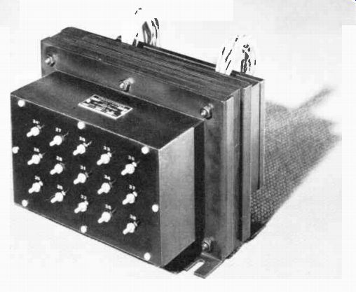
---------- This power transformer has a number of taps so that, by making
connections to the proper terminals, the desired output voltages can be obtained.
Courtesy Langevin Mfg. Co.
This degree of coupling, called the coefficient of coupling, is rep resented by the letter "k". If unity coupling were possible, k would equal 1. If only half of the lines set up by the first or primary coil cut another or secondary coil, or all of the lines cut only half of the secondary, k is .5. That is, the co efficient of coupling is close to zero if the inductors are widely separated and near 1 if they are close together. The coupling is said to be "tight" when the co-efficient of coupling is high, and "loose" when the coefficient is low.
SYMBOLS
Since schematic diagrams will continue to form not only an important part of your studies and laboratory projects, but are needed continually by the practical technician in his work, the symbol for a transformer is given in Figure 14. The loops represent the turns of wire in the coils, the extended lines at each end of the series of loops represent the circuit connections, and the parallel lines in the center represent an iron core. No attempt is made to indicate the number of turns in each winding, although the operating voltages may be indicated as shown.
This symbol is a common type of "power transformer", the primary operates on the ordinary 110 volt house a-c lighting circuit, and is indicated by the coil on the left. Because the house lighting circuit voltages may vary in different locations, the symbol shows that the winding is tapped for operation at 100, 110, or 120 volts.
To explain the operation of these taps, suppose the transformer is designed on the basis of 10 turns per volt. That means a drop of one volt across each 10 turns of the primary and an induction of one volt for each 10 turns of the secondaries. Under these conditions, that portion of the primary indicated by the "100 v" arrow contains 10 x 100 or 1,000 turns.
As the primary and secondary voltages are proportional to the number of turns the 6.3 volt secondaries have 10 x 6.3 or 63 turns and 500 volt secondary has lox 500 or 5,000 turns.
Now suppose the supply rises to 110 volts. Connected across the 1,000 turn primary the drop will be 1,000 divided by 110 or 9 turns per volt approximately. Under these conditions the 6.3 volt windings develop 63 divided by 9 or 7 volts and the 500 volt winding will develop 5,000 divided by 9 or 555 volts, approximately.
To prevent this undesirable rise in secondary voltages, the 10 turns per volt factor is re-established by adding 100 turns to the primary winding between the 100 and 110 y taps. With the 110 volt source connected as shown by the arrow, 110 volts across 1,100 turns provides the normal 10 turns per volt drop and thus produces the normal secondary voltages.
The increased number of primary turns compensates for the increased voltage, the turns ratio of the 500 volt winding is now 5,000 divided by 1,100 or 4.55 approximately and 4.55 times the 110 volt primary is 500.5 volts.
Following the same plan, an other 100 turns on the primary will provide normal secondary volts with a 120 volt supply.
Referring again to the symbol of Figure 14, three secondary windings are shown each with a middle connection or "centertap". The upper winding develops 6.3 volts, the center winding 500 volts and the lower winding, 5 volts.
Thus, by a comparatively simple symbol, the circuit arrangements and voltages of a typical power transformer with four windings and 13 external connections are shown. As far as the circuit connections are concerned, the symbol provides complete information.
According to this plan, any inductor or transformer can be rep resented by an accurate symbol.
If no iron core is used, the central parallel lines are omitted. In fact, these parallel lines some times are omitted from the diagram where there can be no question that an iron core inductor or transformer is used.
In Figure 15, the 117 volt a-c is changed by the transformer into the desired voltage. The diode rectifies the a-c to get d-c. However, this d-c is not smooth enough to be used directly in other tube circuits; capacitors CD, and C19 and resistor R14 are needed. These have not been explained yet, and therefore, the next lesson is about resistors.
IMPORTANT DEFINITIONS
COUNTER EMF--The voltage induced in a wire by self induction which opposes the applied voltage. Also called back emf.
COEFFICIENT OF COUPLING--(k) -A numerical rating between 0 and 1 that specifies the degree of coupling between two circuits. Maximum coupling is 1 and no coupling is 0.
EDDY CURRENTS-[ED i KER ents]--Circulating currents produced in connecting materials by a varying magnetic field. Eddy currents are undesirable in the core of a transformer.
FLUX LINKAGE--The linking of the magnetic lines of force with the conductors of a coil. The value obtained by multiplying the number of turns in the coil by the number of magnetic lines of force passing through the coil.
INDUCTIVE COUPLING--[in DUHK tiv KUHP ling]--The coup ling or linkage of two circuits by the changing magnetic lines of force.
LAMINATION-[lam i NAY sh'n]--A thin layer or sheet. As used here, the term refers to the thin iron pieces used to build up the core of a transformer.
MUTUAL INDUCTANCE (M)-[MY00 : chew al in DUHK tans]- The ability of one conductor to induce an emf in a nearby conductor when the current in the first conductor changes.
MUTUAL INDUCTION-[MY00: chew al in DUHK sh'n]-The electromagnetic induction produced by one conductor in a nearby conductor due to the variable flux of the first circuit cutting the conductors of the second circuit.
PRIMARY- (P)-[PRIGH mer i]--That winding of a transformer which is connected to and receives energy from an external source of electrons. Also frequently referred to as the input winding.
SECONDARY--(S)-[SEC uhn der i]--That winding of a transformer which receives its energy by electromagnetic induction from the primary. Also frequently referred to as the output winding. A transformer may have one or more secondaries.