AMAZON multi-meters discounts AMAZON oscilloscope discounts
Lesson AEH-12B
ELECTRONS INSPECT FOOD
Visit a modern candy factory. An end less conveyor belt carries bulk candy slowly past an inspector who, with a pair of tongs, picks out various pieces of the candy, seemingly at random. The selected pieces are discarded, although to the naked eye, their appearance is exactly the same, as all the other pieces. However, the inspector is using an X-ray device, and particles of foreign material such as small stones, nails, glass, etc. are revealed on a fluoroscopic screen.
X-rays and other invisible radiations are employed in numerous similar applications, and their detection and measurement re quires electronic instruments. Besides detecting hidden flaws in materials, X-rays are used in medicine for diagnosis and therapy.
Infrared rays are used in navigation and for heating and aging industrial products.
Fundamentals
POWER SUPPLY CIRCUITS
Contents The Functions of the Power Supply Power Supply Transformers Half Wave Rectifiers Full Wave Rectifiers Filter Systems Filter Capacitor Filter Inductor or Resistor Regulation Types of Filters The Bleeder Resistor Power Supply Circuits A-C Operated Supplies A-C/D-C Operated Supplies A Commercial Radio Receiver
Many people are "marking time" in their chosen trade or profession because they haven't had the preparation to take them farther. Somebody better qualified is always ahead of them. If they but knew it, they could soon become superior in their work through home study.
-Webster H. Pearce
POWER SUPPLY CIRCUITS
To the average American it is very difficult to understand that the television receiver in his home, a hearing aid, a uranium detector, a large broadcast transmitter, or the new gigantic electronic computers are all part of one field that is called electronics. What he doesn't know is that all of these pieces of equipment use the same basic principles, the same components, in fact many of the same - circuits. The big difference is that these circuits are assembled in new combinations to meet the particular need.
Already we have described for you resistance, inductance and capacitance along with several components that use these characteristics. Among these components are resistors, rheostats, potentiometers, inductors, transformers, capacitors, and diodes. Although others will be added later, they all work on these same basic characteristics.
The next step is to combine several components into a circuit and see just how an overall action is accomplished. Possibly the one circuit that is found in more equipment than any other is the power supply. This is easy to understand when one considers that all circuits need electric power, and therefore, a first step for any equipment is to provide power in the forms needed.
Reviewing the action of the electron tube rectifier, it requires a relatively low a-c or d-c voltage to supply the current which heats the filament to a temperature needed for electron emission. The emitted electrons are attracted by and reach the plate only when this plate is positive with respect to the filament. The plate circuit re quires a relatively high voltage.
Many other types of electron tubes require similar voltages.
That is, they also must have a relatively low a-c or d-c voltage for the filament or heater and a relatively high voltage for the plate. In fact, these plates must be supplied a steady d-c voltage.
Batteries of the proper voltages still are used to supply power to portable apparatus, but their bulk, expense, and inconvenience make them quite unsatisfactory for most other types of electronic equipment. In the majority of the cases, the most readily available source of electric energy is the a-c supplied by utility companies for commercial lighting and power.
To supply the needed d-c voltages, each complete unit of electronic equipment normally includes tubes and other parts for the sole purpose of converting the commercial power to the forms useful to the apparatus, and this section is known as the power supply even when it is included as part of the equipment.
Low alternating voltages are obtained either by means of a step-down transformer, or by connecting circuit elements in series with the power line. D.C. voltages are produced either by rectifying the high alternating voltage obtained across the secondary of a step-up transformer, or by rectifying the power line voltage directly.
THE FUNCTIONS OF THE POWER SUPPLY
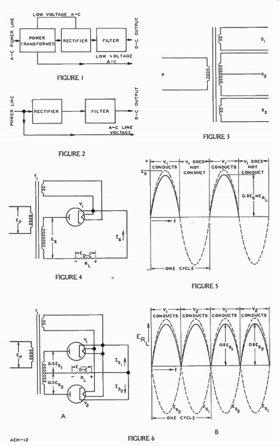
When a transformer is included in the supply, it is known as the power transformer. The general arrangement of this type of supply is illustrated by the block dia gram in Figure 1, and it contains a transformer, a rectifier, and a filter composed of capacitors and resistors or inductors.
With these components, the power supply performs three major functions. First, the power line voltage is transformed to the desired higher and lower values needed by the various circuits of the electron device operated by the supply. The low a-c is used for the heaters or filament of the tubes. The rectifier usually has a separate heater or filament winding on the transformer from that used by the other tubes in the circuit. Second, the high alternating voltage is rectified. The output of the rectifier is a series of voltage pulses, all of the same polarity.
Third, this pulsating direct voltage is "smoothed" by the filter to form the steady or constant voltage required.
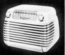
------------ Table model radio receiver. The power sup ply is built in.
Courtesy Sentinel Radio Corp.
To reduce both cost and weight where the line voltage is sufficiently high for the application, another common type of power supply does not contain a transformer, as shown by Figure 2.
Here, the alternating voltage of the power line is applied directly to the rectifier. Again it produces a pulsating direct voltage which must be smoothed by the filter.
POWER SUPPLY TRANSFORMERS
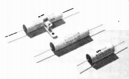
------------- Type of high wattage resistors found in power supplies. Note
the strap which is used for rigid mounting. Courtesy Sprague Electric Co.
As we explained in an earlier lesson, the power transformer operates on the principle of electro-magnetic induction. When the primary winding is connected to a source of alternating voltage, the resulting current produces a constantly changing magnetic field which cuts the secondary and induces an alternating voltage in it. With respect to the primary, a secondary voltage is determined by the turns ratio between the primary and secondary windings.
To provide the high and low voltage outputs needed, the power transformer normally contains several secondaries. A common arrangement is illustrated by the transformer symbol in Figure 3.
P is the primary winding, and coils S1, S2, and S3 are the secondaries. Having fewer turns than the primary, S1 and S3 are low voltage secondaries. Typical voltages produced across these windings are 2.5 v, 5 v, 6.3 v, and 12.6 v. S2 is called the high voltage secondary. Usually, it has more turns than the primary to produce 300 or more volts, and a lead connected to its center makes it possible to use this winding in a full wave rectifier circuit.
HALF WAVE RECTIFIERS
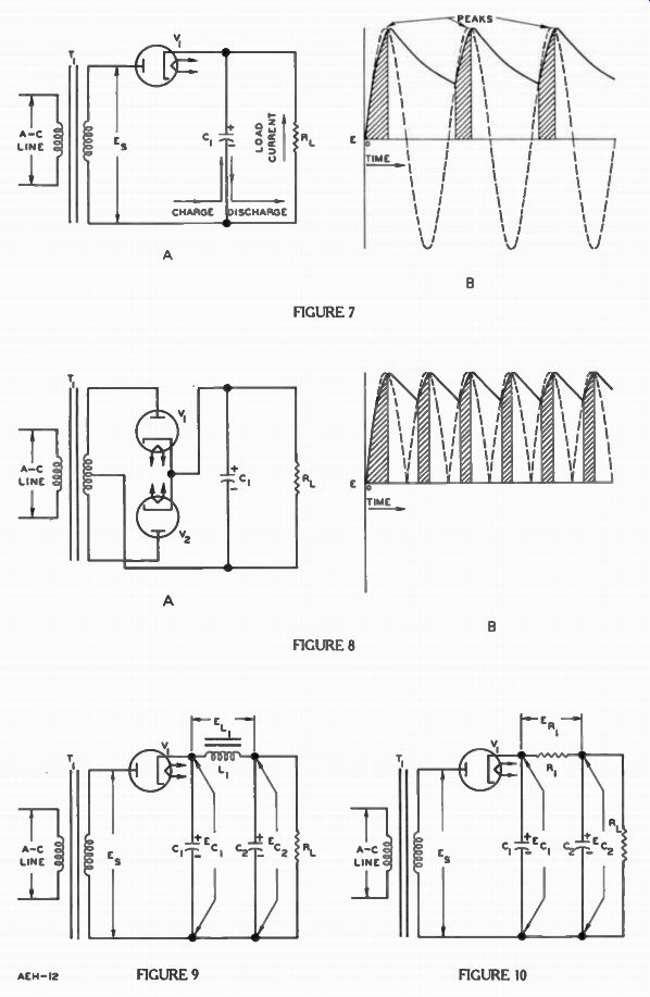
The action of the basic half wave rectifier circuit shown in Figure 4 was explained in the les son on diodes. Reviewing briefly, secondary voltage Es is applied across diode V1 and resistor 1%, in series. When the plate of V1 is positive with respect to its cathode, it conducts and the electron flow I s is in the direction of the arrow. The secondary voltage Es is shown in Figure 5 as the bro ken line wave-form.
As indicated by the arrow at the bottom labeled t, passage of time goes from left to right on the page. This is used often instead of marking the horizontal line off in seconds where the actual unit of time used is not important to the illustration. For the same reason, letter Es and the + and - signs indicate that the voltage increases the further away the wave-form is from the horizontal line without stating some particular voltage. Whether the secondary voltage Es described here is 100 volts, 250 volts, or even 1,000 volts, the basic action remains the same.
Since some of the secondary voltage appears across V1 due to the internal resistance of the diode, only about .9 of the positive alternation appears across resistor Rh. Of course, none of the negative alternation appears across RL, and therefore the voltage for Rh remains at zero during this alternation as indicated by the solid line waveform.
FULL WAVE RECTIFIERS
The basic full wave rectifier circuit, shown in Figure 6A, includes two rectifiers, V1 and V2, and transformer T1 . For direct comparison with Figure 4, transformer T1 is the same in both circuits, but in Figure 6A, the secondary has a center connection or "tap". Here, the circuit connected across each half of the secondary is like that across the entire secondary of Figure 4. Thus, the voltage Es, applied across tube V, in Figure 6A is only HALF of that for Figure 4 or .5 Es. In like manner, Es, across V2 also is .5E8.
During the alternations that the upper end of the secondary is positive with respect to the center tap, rectifier V1 conducts and allows electron flow in the direction indicated by the I s, arrow. When Es, or the lower end of the winding is positive, rectifier V., conducts electrons in the direction of the I s, arrow. During the positive alternation of Es, current I s, is carried by RL, V1 and the upper half of the secondary T1 , while during the next alternation when Es, is negative and Es„ is positive, I s, is carried by RL, V2 and the lower half of the secondary. For both alternations the direction of current RL is in the same direction.
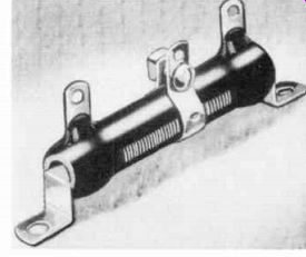
------------ Rated at 10 watts, this resistor is used bleeder in a power
supply. Courtesy Ohmite Mfg. Co.
Thus, in a full wave rectifier, there is voltage across the load resistor during the full cycle. ER L has the form shown in Figure 6B. As explained for Figure 4, the magnitude of the rectifier output pulses is 90 percent of the input voltages Es, and Es„. With pulses during both alternations, in the full wave rectifier circuit, the voltage Es„ across the load is equal to 90 percent of .5Es. Assuming transformer T1 has the same primary voltage E, and the same turns ratio in both circuits, the voltage applied to each rectifier section of Figure 6A is only half that applied to the rectifier of Figure 4.
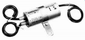
-------------- Electrolytic capacitor with two 8 uf sections. The negative
plates are tied to o common lead. Courtesy Songamo Electric Co.
Figures 5 and 6B show the output of the rectifiers tubes in the circuits of Figure 4 and 6A. The voltages vary all the way from 0 to the peak and back to zero again.
Unfortunately, such d-c voltages are not satisfactory for most needs. Most tubes require a d-c voltage with very little change in amplitude. To do this requires an added circuit; a combination of capacitors and inductors or resistors called a filter. When used for this purpose, these components are called FILTER CAPACITORS, FILTER CHOKES AND FILTER RESISTORS. FILTER SYSTEMS
Filter Capacitor
In Figure 7A, filter capacitor C1 is connected across resistor It i , which represents the "load" or circuits drawing current from the half wave rectifier. As the first rectifier pulse rises, electrons flow into the- lower plate of C1 in the direction of the charge arrow and out of the upper plate, through the rectifier V1 and the secondary.
This action charges the capacitor until the pulse reaches its peak when it is charged to peak secondary voltage E. At the same time, electrons also flow through I_1,, in the direction of the load current arrow, through rectifier V1 and the secondary, back to the bottom end of It,. Then, as the secondary voltage decreases, the capacitor discharges. Because the rectifier permits the flow of electrons only in the direction of charge, the capacitor cannot discharge through the transformer secondary. There fore, electrons flow in the direction of the discharge arrow from the lower plate of C1 through R1 to the upper plate.
The relatively high resistance of R., limits the current to such a small value that it takes a long time for C1 to discharge. There fore, the load current and capacitor voltage do not decrease as rapidly as the secondary voltage.
Capacitor C1 is discharged only partially by the time the next pulse recharges it to the peak voltage again.
As a result of this action, the load voltage pulses are no longer like those in Figure 5. In Figure 7B the dashed line curve represents the secondary voltage E. The solid line curve represents the variations of the charge on capacitor C1 , and the voltage across C1 and RL. This alternating voltage across the filter capacitor is called the ripple voltage, and is a component of the output voltage. The alternations of secondary voltage Es which make the diode plate positive charge C1 until the peak value is reached.
This time during which V, con ducts and C1 charges is indicated by the shaded area under the curve. Thereafter, C1 discharges slowly through RL for a relatively long period indicated by the un shaded areas until the next rising positive pulse exceeds the voltage remaining on capacitor CI; then C, charges again. Since RL represents the load, the load current has the same wave-form as the solid line voltage curve of Figure 7B. As explained in a later lesson on combinations of resistors and capacitors, by choosing C1 and R1 properly, the discharge is small thus producing a small ripple voltage. The less the capacitor discharges from the peak voltage, the smaller the ripple and the smoother is the d-c output voltage.
A similar action occurs when a filter capacitor is placed across the load terminals of the full wave rectifier circuit in Figure 8A. Again, capacitor C1 charges during part of the rising portion of each positive pulse, and then discharges through RL until the next pulse arrives. In this case, the lower plate of the capacitor C1 connects to the center tap of the secondary. For each cycle of the applied voltage, the upper end of the secondary is positive during one alternation and the lower end positive during the other alternation with respect to the center tap.
Hence, two positive pulses charge C1 during each cycle.
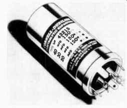
------------ A power supply filter capacitor designed for upright mounting.
Either stomped into the metal or printed on the label are the capacitor section
ratings and working voltage ratings. Courtesy Cornell-Dubilier Electric Corp.
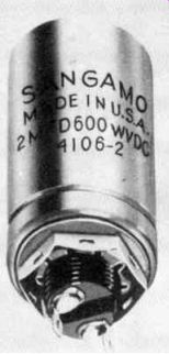
------------ Threaded bushing and hex nut are used to mount this electrolytic
capacitor. Usually a lock washer is included when this capacitor is mounted
in power supplies subject to excessive vibration. Courtesy Sangarno Electric
Co.
In Figure 8B, the dashed line curve represents the series of charging voltage pulses applied across C, and RL and the shaded areas represent the charging time for capacitor C1 . Like Figure 7B, the solid line curve shows that C1 charges to the peak voltage of each pulse, and then discharges through R1 , until the next pulse arrives to recharge it. This curve also has the same wave-form of the voltage across C1 and RL, and the current in RL. For the same line voltage frequency, in Figure 8 the applied pulses occur twice as often as those in Figure 7, and therefore, C1 has a shorter interval for discharge. Consequently the variations or ripple voltage across C1 is less in the full wave circuit when employing the same filter as the half wave circuit.
Filter Inductor or Resistor
In most electron applications, the filter action of a single capacitor does not produce a sufficient reduction of the ripple voltage.
Therefore, additional units must be added, like the filter choke L1 and capacitor C2 shown in Figure 9.
The choke is an inductor consisting of a single winding on an iron core, and its filter action is due to the self-induction which opposes any change in current.
Connected in series with the rectifier and load, the choke carries the entire load current. As the applied voltage Es causes the current to rise, the self-induced voltage in the choke opposes the change, and thus prevents the current from rising immediately to its peak.
The filter input capacitor, C1 charges to the peak of the applied voltage during the first current pulse in the same manner as C1 in Figure 7. Then, as Es decreases, C1 discharges through RL and LI, thus reducing the rate at which the load current decreases. At the same time, this decreasing load current induces a voltage in the choke in a direction which tends to maintain the current.
During the first cycle, a pulse of current causes the filter output capacitor C., to charge to some extent, but not to the peak of the applied voltage because, at this time, most of this voltage is needed to overcome the induced counter emf of L1. However, during the next few cycles, the current variations are reduced, as a result the voltage across L1 is lower. and C2 charges to its final operating voltage, E02.
L1 and C2 are connected in series across C1, therefore the sum of their voltages, EL, + Eco, is equal to E01 . The voltage E02 forms the output voltage of the filter, and is applied across the terminals of the load R1. In Figure 9, the voltage Ec, is composed of two components, one direct voltage, and the ripple which varies up and down at the power line frequency. The inductor has a counter emf which op poses only the a-c or ripple, there fore, most of the a-c voltage appears across L, and very little across C2. On the other hand, L1 offers minimum counter emf to the direct voltage. Hence, very little of this component appears across L1, leaving almost all of it across C2. Although Ec, is divided into the two parts, EL, and E02, these voltages do not have the same proportions of the two components. EL, is mostly alternating voltage, while the filter output voltage E02 is almost entirely direct voltage.
In applications where the load requires a small current, often the choke of Figure 9 is replaced by the filter resistor shown as R1 in Figure 10. It is connected in series between the rectifier and load RL, and forms the series arm of the filter, CIRIC2.
In Figure 10, the voltage Ec, is applied to R1 and C2 in series. Resistor R1 does not discriminate between frequency components, but since C2 passes a-c frequencies and blocks the direct voltage component, a part of the direct voltage and most of the alternating voltage appear across RI, while the output voltage Ec, is almost entirely direct voltage.
Since the direct voltage drop ER, across resistor R1 is lost insofar as the load is concerned, it is desirable that this voltage be kept low compared with the direct voltage E02 across the filter output.
According to Ohm's law, for a given current ER, is directly proportional to resistance of R1. The relatively low cost, size, and weight of a filter resistor make it advantageous in those applications which do not require a large current from the power supply such as a table model radio. When a large current is needed, the filter choke is used.
The filters of Figure 9 and 10 are called pi-type, low-pass filters.
The word pi comes from the fact that the filter as it is usually drawn in a schematic diagram looks like the greek letter e called pi. The term "low pass" refers to the fact that the filter reduces the amplitude of alternating currents and that the higher the frequency the greater the reduction because the capacitors have less time to discharge between alternations.
As shown by the solid line curve of Figure 7B, once the input capacitor C1 has been charged by the first rectifier current pulse, it never becomes completely discharged while the power supply is in operation. The voltage Ec, in Figures 9 and 10 has polarity opposite that required to produce current in the circuit made up of CI, V1 , and the transformer secondary winding.
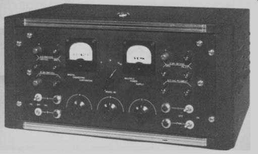
------------- Front view of a complete laboratory power supply having
three ranges of variable voltage. Courtesy Bristol Eng. Corp.
After the first pulse, current can exist in this circuit only when Es has sufficient amplitude and proper polarity to overcome the capacitor voltage E1. In Figures 7B and 8B the narrow shaded areas indicate that this period is short and exists between the point on the rising slope when the Es is equal to Eci and the peak of the applied voltage. For this reason, the transformer and rectifier provide energy in short pulses to the filter input capacitor.
Usually the load requires a constant supply of energy from the power supply. Hence, the filter is a device which receives energy in short pulses of rectified current and stores the electric energy in the capacitors from which current is taken steadily by the load as needed.
Regulation In the circuits of Figures 9 and 10, any sudden increase of current required by R1 , is supplied by electron flow from the lower (negative) plate of C2, through IL, and into the upper plate of C2. This flow decreases the voltage across C. and R1 . until the capacitor is recharged by electron flow from the negative plate of C1 , out of the upper plate of C2, through L1 or R1 and into the positive plate of C1. In most electron applications, it is necessary that the power supply output voltage remain nearly constant regardless of load current variations during the normal operation of the equipment. This important power sup ply characteristic is referred to as regulation.
As mentioned for Figure 9, an increase in load current decreases the charge stored in the output capacitor C., and therefore, decreases the available output voltage Ec.,. It requires an increase in current in the choke to recharge C2, and the resistance of the wire in the choke winding increases the direct voltage drop across this unit, thereby reducing the direct voltage available across the output terminals of the filter. More over, the increased current reduces the charge on C1 and there fore, the rectifier current pulses must increase to recharge C1. The increased current is carried by rectifier V, and the secondary winding of the transformer. Since both have some resistance the increased voltage drop reduces the portion of Es which is available for charging C1. To reduce these undesirable effects, the filter capacitors should have high capacitance; the choke should provide high inductance; and the transformer secondary, the rectifier, and the choke should contain low resistance.
In practice, each power supply is designed to provide a certain maximum current, known as the "full load". On the other hand, when no current is taken from it, the supply is said to be operating at "no load". The voltage at the output terminals is highest under no load conditions, and reduces to some definite value at the rated full load current. The less the output voltage changes with load current variation, the better is the regulation, and since most circuits work best at some particular voltage, GOOD REGULATION is a desirable power supply characteristic.
Types of Filters
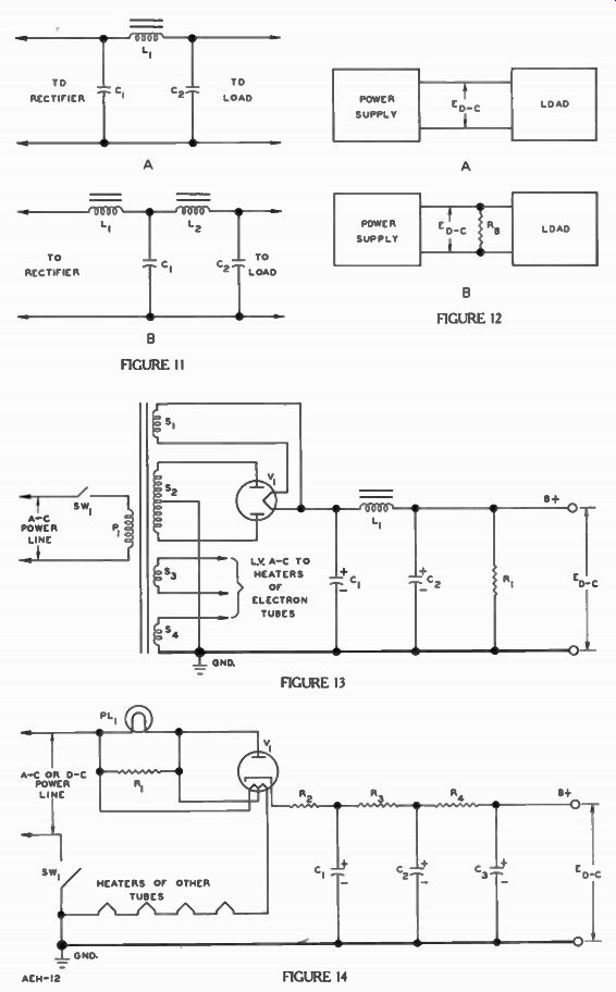
Besides their classifications as low-pass, the filters employed in power supplies are designated as to the nature of the component at the input or rectifier end. In the pi-type filter of Figure 11A, capacitor C1 forms the input component, and therefore, this arrangement is called a CAPACITOR INPUT or "condenser input" filter.
This type is employed in the circuits of Figures 9 and 10. The unit of Figure 11B is composed of two "L-sections", C1 and L., C2, and since L1 forms the input component, this arrangement is called a CHOKE INPUT filter.
The choke input filter provides better regulation, and generally is employed in the applications which require heavy load currents with good regulation. On the other hand, the capacitor input arrangement provides a somewhat higher output voltage with a given power transformer and rectifier.
Therefore, it is used for equipment which operates with a relatively light load current and does not have such high regulation requirements.
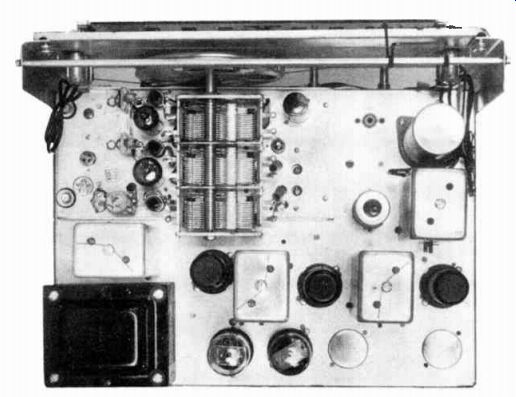
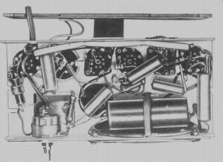
------------ Top view of a radio receiver. Note the transformer in the
lower left-hand corner and the electrolytic capacitor in the upper right-hand
corner. Courtesy Capehart-Farnsworth Corp.
The most common power sup ply filter arrangements are shown in Figures 11A, and 11B. Figure 11A is a single section, pi-type filter; Figure 11B consists of two L-section filters.
THE BLEEDER RESISTOR
To show the complete current path, the power consuming equipment or load was represented by resistor R, in Figures 7, 8, 9, and 10. However, the load is not a part of the power supply proper.
In Figure 12A, the transformer, rectifiers, and filter are represented by the block labeled power supply. The output voltage, Ed.„ is applied to the load block, which represents the combination of circuits and components which receive their d-c operating voltages and currents from the power supply.
Under usual operating conditions, the total resistance of the load varies from time to time, that is, the power supply must deliver more or less current. As mentioned before, the output voltage Ed.c varies with changes in load current, and the less these variations are, the better the regulation.
To improve the regulation, it is common practice to employ a bleeder resistor across the output terminals of the filter, as shown by resistor R. in Figure 12B. Thus the supply must furnish a total current which is equal to the sum of the load current plus that carried by the bleeder. The resistance RB does not change, there fore the bleeder current depends only upon Ed., and RB, and so it is relatively constant.
With the load connected across the bleeder, its current is only a portion of the total output, and any variations in the load current result in smaller changes in the total supply current. Thus, the changes in Ed-, with load current variations are reduced; that is, the use of the bleeder resistor improves the regulation. Also, when the load is disconnected, the bleeder provides a discharge path for the power supply filter capacitors.
POWER SUPPLY CIRCUITS
One of the most common ways to classify a practical power sup ply circuit is according to the type of current it is designed to work from. Using this classification; there are A-C SUPPLIES, D-C SUP PLIES, and those which operate from either a-c or d-c called A-C/D-C SUPPLIES.
A-C Operated Supplies
Most a-c operated power sup plies employ a power transformer in a typical circuit very similar to that shown in Figure 13. Here, power transformer T1 has five windings: primary P1 , secondaries S1, S2, S3, and Sq. In series with P1 and one side of the a-c power line, switch SW1 makes it possible to turn the power supply and the attached equipment on and off. Both diodes are combined in one tube envelope and use the same heater. ' Secondaries, S1, S :,, and S4 have fewer turns than P1 , and there fore, provide operating voltages lower than that of the power line.
Connected as shown, S1 provides a-c to heat rectifier tube V1, while S3 and S4 provide heater currents for the electron tubes in the equipment. In this example, S3 is connected to the heaters by means of two leads in the same manner as S1 connects to the V1 filament.
However, only one lead from S4 connects directly to the heaters supplied by this winding. The other end of S, is attached to the metal frame or chassis on which the various components are mounted.
Being electrically conductive, the chassis usually is employed as part of one or more of the circuits in the unit, and provides a convenient means of completing these circuits with a resultant saving of wire conductors. Usually referred to as ground (gnd.), the chassis connection is designated by the symbol near the lower end of S4. Depending upon the application of the electron unit, the chassis may or may not be connected by a conductor to the earth to form an "earth ground". In the circuit of Figure 13, one terminal of each heater, supplied current by is connected to the upper end of the S 4 winding by means of the lead indicated. To complete the circuit, the remaining heater terminals connect to the chassis or "ground". With more turns than P1 , secondary winding S2 produces a voltage step-up, and this high alternating voltage is applied to the plates of full wave rectifier tube V1. As shown, the center tap of the negative plates of filter capacitors C1 and Co, and the lower end of R, all connect to ground.
Basically, this circuit is just like the full wave rectifier of Figure 8A. Although not included in the Figure, the load is connected in parallel with bleeder resistor R1; that is, from the upper output terminal marked "B + ", to the lower terminal connected to ground.
Tracing the d-c path in Figure 13, when the applied voltage makes the upper plate of V, positive, electrons are drawn from the filament to this plate, and flow through the upper half of S2 to the center tap, to ground, through R1 and the load to B + and through L1 to the filament of V,. When the applied voltage makes the lower plate of V, positive, electrons are attracted from the filament to this plate and flow through R1 , the load, and L1 to the filament of V1.
As explained for the filter of Figure 9, during the short intervals rectifier V1 conducts, capacitors C1 and C. are charged by electron flow from ground into their lower negative plates. Then, supplied by C1 and C2, a continuous flow of electrons is carried by R1 , the load, and L1 during the intervals when V1 is not conducting.
With C1 connected from the filament of V1 to ground, the filter is of the capacitor input type like that of Figure 11A, and includes the iron core choke L1 and capacitor C2. Often capacitors C1 and C2 are of the electrolytic type and R1 is the bleeder resistor. As indicated, the ungrounded output terminal of the power supply is referred to as the "B +" or "B plus" terminal.
------------ Bottom view of a table model radio receiver chassis showing
its components. Note the placement of the large electrolytic capacitor on the
lower right. Courtesy Motorola Inc.
A-C/D-C Operated Supplies
A power supply which may be operated from either an a-c or d-c source, as shown in Figure 14, does not include a power trans former since transformers cannot operate with d-c. Hence, the power line connects directly to the rectifier circuit. The heater of the half wave rectifier tube V1 and those of the other tubes used in the equipment are connected in series across the power line.
In the Figure, the upper side of the power line connects through the parallel circuit of pilot light PL1 , resistor R1, and half of the heater, to the plate of half wave rectifier tube V1. The other side of the power line connects through the off-on switch SW1 to ground.
The filter, containing Cli C2t C39 R3, and R4 is a two-section, pi type unit. Low resistance R2 is not a filter resistor; it has just sufficient resistance to prevent a damaging surge of rectifier current while C1 receives its initial charge when SW1 is first closed.
Therefore, capacitor C1 is the actual input component of the filter.
When the power line supplies a-c, the rectifier passes a pulse of current during the peak of each alternation in which the upper supply line is positive with respect to the line connected to ground. These pulses of current charge the filter capacitors as explained previously for Figure 10, and the voltage across C3 is avail able as the supply output voltage.
When the power line supplies d-c, the positive side of the line must be connected to the upper input lead in Figure 14, and the negative side through SW1 to ground. After an initial surge which charges the filter capacitors, the rectifier conducts continuously, but only carries the relatively small current required by the load.
Actually, the rectifier circuit is not needed when the line supplies d-c, but as used the arrangement provides a convenient means of operating with either type of in put without making any circuit changes. The power supply filter removes any variations in the power line d-c to provide a steady voltage at the output terminals of the supply.
Connected in series with the power line and the plate of V1, lamp PL1 lights the dials on the front panel of the equipment. The PL1 filament current is supplied by the V1 plate current as well as the current drawn by the other tube heaters in series. R1 and half of the V, heater carry part of these currents since both are in parallel with PL1.
A COMMERCIAL RADIO RECEIVER
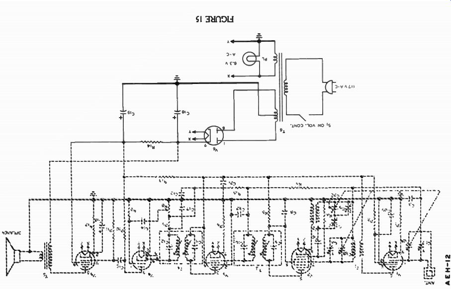
As we pointed out earlier in this lesson, power supplies are used in practically every possible type of electronic equipment. A very typical application is in the table model radio receiver shown in black in the schematic diagram of Figure 15. Although the grey portion of the diagram is not described until later lessons, the en tire diagram shows how this power supply provides both a-c and d-c for the circuits.
This is the same power supply shown in previous lessons and it is very similar to the circuit shown in Figure 13. As usual a 117v a-c source supplies current to the primary of transformer To. The secondaries of this transformer provide the correct voltages and the high voltage winding has a center tap to permit full wave operation by the two diodes in tube V. Note that tube V5 uses the voltage directly from the in put capacitor C18 through the primary of transformer T5. This is a means of securing a high voltage and heavy current for V5 without using a filter choke in stead of resistor R14.
All of the tube heaters connect to the 6.3 volt secondary.
The terminals marked "X" are all connected together and so are the "Y" terminals. Therefore, all of the heaters are in parallel across this heater winding. Also, across this winding is a small light bulb called the "pilot light" which is used to light the tuning dial.
The symbol for it is the circle with a single loop in it.
Naturally, you must wonder what each of the other tubes in this radio diagram do. Since these very same circuits are used in many other types of equipment we shall describe each in turn and when it is explained it will be shown in black on the diagram. In this manner, before the next six lessons are completed you will understand the overall operation of this receiver.
Possibly as a first step toward this goal, we should explain how "energy converters" work, since at least one is found in every radio or television receiver.
IMPORTANT DEFINITIONS
BLEEDER RESISTOR-A resistor connected across the output terminals of a power supply to improve the regulation by carrying a continuous, fixed current.
CHASSIS-[SHAS i] -The frame or base, usually metal, on which the tubes and other components of an electron unit are mounted.
GROUND- (GND)-A conductive body which serves to complete an electric circuit, and usually provides the reference potential for measurement of voltages in an electron device.
POWER TRANSFORMER-The transformer employed to obtain the required voltage step ups and step downs in an a-c operated power supply.
REGULATION--With regard to power supplies, a measure of the change in output voltage due to a change in load current. The less the voltage change, the better the regulation.
RIPPLE--In the output voltage of a rectifier circuit, the alternating or varying voltage component.
WORK DIAGRAM
Connect these four resistors in series across the 90v. battery in such manner that the indicated polarities are correct and the potential difference between points C and E is 60 volts.
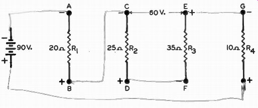
----------- When you have finished, check with the answer on the back of the fold-out sheet.
------------
WORK DIAGRAM SOLUTION
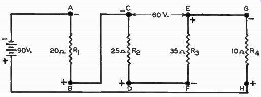
-------------
---------------
----------------
------------
FROM OUR NOTEBOOK
TAKE TIME to …
Take time to work--it is the price of success
Take time to think-it is the source of power
Take time to play-it is the secret of perpetual youth
Take time to read-it is the fountain of wisdom
Take time to be friendly-it is the road to happiness
Take time to dream-it is hitching your wagon to a star
Take time to love and be loved-it is the privilege of the gods
Take time to look around-it is too short a day to be selfish
Take time to laugh-it is the magic of the soul.
- Leinster Leader: Irish Digest
Yours for success,
DIRECTOR