AMAZON multi-meters discounts AMAZON oscilloscope discounts
INTRODUCTION
Electronic and electrical drafting and design projects are drawn almost exclusively with multiview orthographic projection for the engineering and production stages of a project. Pictorial sketches are used extensively in the design and engineering stages to clarify design configurations and in working sketches to show optional de signs. Pictorials offer a greater freedom in creative communication among engineers, designers, and drafters. Their usefulness, however, is quite limited as a means of communicating production and engineering manufacturing data.
Formal pictorial illustrations with perspective, axonometric, and oblique projections are used throughout the electronic field to communicate data to nontechnical personnel and to clarify assembly or sales information to equipment users. Technical manuals, sales brochures, user manuals, assembly manuals, service and repair manuals, abstracts, and parts catalogs all make liberal use of pictorial communication. Although a photograph of a particular part or assembly offers the most accurate and realistic representation of an object, the dimensional and assembled characteristics of the object cannot be fully understood without a logical view orientation and technical data associated with line drawings (line art) and pictorials. FIG. 1 is a photograph of two wiring structures. FIG. 2 shows a pictorial drawing of a side entry U-clip terminal used for solderless connections. Each figure has advantages and disadvantages. In many sales catalogs, photographs and pictorials are combined in order to clarify a situation, as in FIG. 3, where the Klipwrap Post is depicted in the photograph with a blowup, inset view of an isometric pictorial. The combination of a photograph with a drawing provides a greater degree of information for the user, assembler, and purchaser of the part. Note that the photograph was touched up; the components were outlined directly on the photo.
Wiring and chassis details, as well as connection and assembly instructions, can be best understood by both nontechnical and technical users of electronic equipment if a pictorial view or a photograph accompanies the orthographic drawing. In FIG. 4 the wiring diagram of the CRT chassis is shown as an orthographic (top view) pictorial with each of its primary parts called out, or ballooned. This pictorial wiring diagram shows the major wiring and cable information needed for a technical manual that accompanies the product.
Normally, an electronic firm will employ a small group of technical illustrators to do pictorial illustrations needed for sales or manual preparation. In some cases the drafting department is called on to prepare pictorial illustrations. The drafter has extensive knowledge of the object to be illustrated, whereas the technical illustrator is schooled primarily in illustration techniques, with little or no electronic expertise. Drafters usually suffer from limited knowledge of techniques associated with pictorial illustrations: one-plane projections, shading procedures, inking experience, and graphic arts applications for technical illustrations.
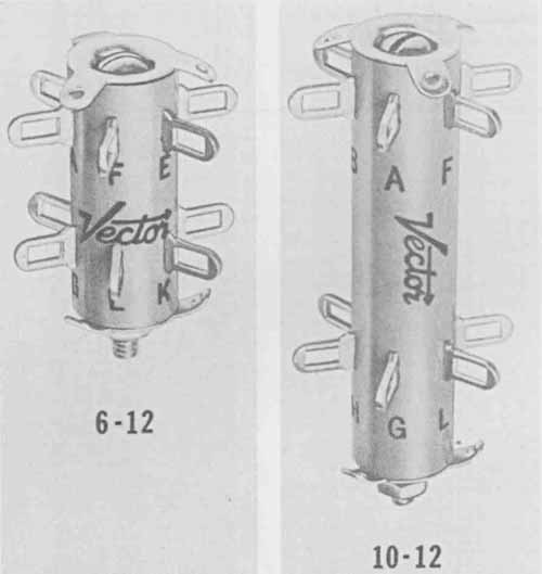
FIG. 1 Wiring structures. (Courtesy Vector Electronic Co.)
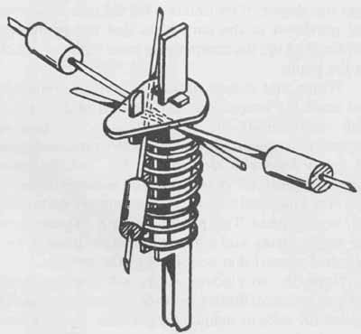
FIG. 2 Pictorial of a side entry U-clip terminal. (Courtesy Vector
Electronic Co.)
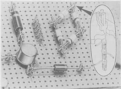
FIG. 3 Wiring post. (Courtesy Vector Electronic Co.)
One of the greatest drawbacks concerning the use of drafting personnel to do technical illustrations lies in the rigid, exacting nature of engineering drawing. A drafter normally finds it quite difficult to take what is referred to as artistic license. A technical illustrator usually shows the object at its best (though perhaps not totally correct) orientation or slightly moves parts of an assembly to better expose them for identification. This ability to adapt and bend the rules is a distinctive skill that must be cultivated for artwork that is not only visually accurate but also artistically pleasing.
The lack of knowledge concerning hand-drawn methods of illustration preparation will no doubt be come less important with the increasing use of computer-aided design systems with technical illustration software packages. Many CAD systems are available that will convert multiview design drawings into single- view technical illustrations.
PICTORIAL ILLUSTRATION CONSTRUCTION
In most cases, an illustration is first sketched in two or more possible arrangements. The best possible view or orientation is then chosen. Proper arrangement, view orientation, and pictorial projection procedure must be determined before the actual drawing is started in order to eliminate time and cost from false starts. After the illustration technique (orthographic, axonometric, oblique, or perspective) and view orientation have been selected, the drawing must be blocked in with a pencil.
FIG. 4 Wiring diagram of a CR1 chassis. (Motorola, Inc., Semiconductor Products Sector)
Two separate techniques are used at this stage. The drawing can be completed in 2H or H lead and then traced in ink with an overlay. (A light table is helpful with this technique.) Or the project can be drawn very lightly with a hard lead, 3H to 6H, and then inked over the top of the penciled lines. When the penciled illustration is complete, it is checked for accuracy and approved by the designer.
The last step in pictorial illustration involves the inking of the project. Proper line thickness and lettering techniques must be established based on the amount of photographic reduction required. In most cases, pictorials are completed at 2:1 or 4 : 1 size. Subsequent reduction will clean up line and corner discrepancies. In other words, the drawing looks better since any problems are also reduced, if not eliminated altogether, by the reduction. Proper spacing of lines and forming of letters are essential for the drawing to be acceptable in its reduced stage.
This section is meant to be an introduction to the area of pictorial projections. It provides examples of pictorials in all their variations. (Pictorial examples and projects are also provided at the end of Section 4 and throughout the text.) To better understand these illustrations, consult the following standards: Pictorial Drawing: ANSI Standard Y14.4—1957; A Guide for Preparing Technical Illustrations For Publication and Projection:
ANSI Standard Y15.1; and General Drafting Practice: Military Standard MIL-STD-1.
Pictorial illustrations can be divided into two basic categories: orthographic and 3-plane (simulated 3D). An orthographic illustration normally uses only one of the three common views of the object: front, side, or top. A 3-plane pictorial is more common and gives a greater lifelike appearance since it exposes three sides (three planes) simultaneously: top, front, and right side, for example. A 3-plane projection is divided into two separate categories: parallel line and converging line. Axonometric (isometric, dimetric, and trimetric) and oblique illustrations are parallel line projections. Perspective illustrations are converging line projections.
The simplest type of pictorial drawing is the orthographic illustration, as shown in FIG. 5, which is the front view of a meter measuring DC current. This illustration, communicating the procedure for using the meter, was taken from a user manual. A more complicated perspective, axonometric, or oblique drawing is not needed here.
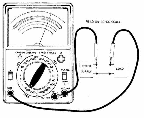
FIG. 5 Pictorial of a meter measuring DC current. (Triplett Corp.)
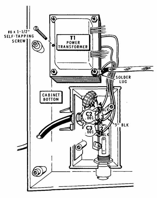
FIG. 6 Perspective pictorial assembly. (HEATH COMPANY)
Axonometric, oblique, and perspective projections are classified as pictorial or 3-plane projections. Axono metric and oblique projections use parallel projection lines, whereas perspective drawings use converging projection lines. Perspective drawings give the most lifelike appearance and in many cases are almost photographic, as in FIG. 6, which shows a wiring assembly.
Perspective projections are the most visually accurate, but also take a considerable amount of time and money. They cannot be as easily scaled or dimensioned as other 3-plane pictorials. Axonometric and oblique projections, on the other hand, are not theoretically correct and contain their own problems of visual distortion, but are easier to draw since they use simplified projection procedures. These two projections are easy to scale from a multiview drawing or from the object itself. They can be precisely dimensioned, since they can be drawn to scale from true length measurements. FIG. 7 shows a variety of 3-plane pictorial component cases illustrating axonometric projection.
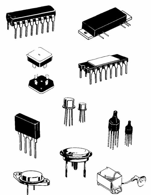
FIG. 7 Pictorial drawings of component cases. (Courtesy Motorola, Inc.,
Semiconductor Products Sector)
Computer-aided design systems eliminate much of the tedium and difficulty of pictorial projections and technical illustrations (and unfortunately some of the feeling of artistic satisfaction). In FIG. 8 the system is used to model and illustrate the cockpit and control panel of an airplane. CAD systems that are not limited to two-dimensional drafting formats normally can de sign and illustrate in three dimensions, as well as model on the screen. The art on the screen can be drawn by the plotter with or without the body elements shown in this figure. Shading and shadows could also be added to create a more lifelike appearance. Technical illustration programs for state-of-the-art CAD equipment, as shown in FIG. 8, allow the production of simple to complex line drawings in any desired projection, including perspective. The technical illustration software package normally has the following capabilities:
-- Unlimited geometric capabilities, including the ability to create drawings from any desired angle
-- 3D drawing capabilities
-- Shading, overlay, and lineweight selection
-- Freehand tablet input
-- Axonometric direct-entry drawing functions
-- Automated part number insertions and ballooning
-- Figure rotation and new view orientation
-- Wide variety of screen fonts for possible direct output to a phototypesetter
-- High-quality and uniform artwork that can be easily reproduced, stored, and plotted at any scale
ISOMETRIC PROJECTION
Isometric projection is based on the theory that a cube representing the projection axes will be rotated until its front face is 45° to the horizontal plane and then tipped forward or downward at an angle of 35° 16’. In FIG. 9, an object has been enclosed in a glass box with the enclosed object projected onto each of its corresponding surfaces. The cube has been rotated 45° and tilted for ward to show all three faces equally. The viewing plane 1—3 is parallel to the projection plane (image plane). The view is an isometric drawing in this case since the cube and object were drawn from true length lines and 30° angles for the receding axes.
In isometric projection all three axes make equal angles with the projection plane. All three axes are equally foreshortened and make equal angles of 120° among themselves. The three faces of the object are identical in size and shape. The projected lengths of each edge appear foreshortened. This type of projection is a true isometric projection, which is seldom used. A true isometric projection is about 81% of the size of an isometric drawing.
(coming soon) FIG. 8 Technical illustration using CAD. (Courtesy American Small Business Computers, Design CAD)
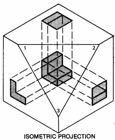
FIG. 9 Isometric projection.
In actual industry practice, isometric drawings are constructed along the three axes, one vertical and the other two receding at 30 degrees to the right and left. Each dimension is measured true length (not foreshortened). In FIG. 10 the printed wiring board showing the component locations and the contact assignments has been pictorially depicted as an isometric drawing. All lines in isometric drawings that are on or parallel to the three axes are drawn true length. Lines not on or parallel to the axes are constructed with offset dimensions.
Isometric drawings are constructed from isometric axes. The Z axis (height) is vertical, the X axis recedes to the right at 30°, and the Y axis recedes to the left at 30° ( FIG. 11).
Isometric Construction
Isometric construction using the box method is illustrated in FIG. 12. The procedure for drawing an isometric box is shown in (1) using 30° triangles. Note that the axes are at 120° to one another. The 90° angles of the box transfer to the isometric projection as 60° or 120°, as shown. The three visible faces correspond to the top. front, and side faces in the orthographic (multiview) projection of the same object (3). Different arrangements are possible for the isometric axes, as long as they remain at 120° to one another.
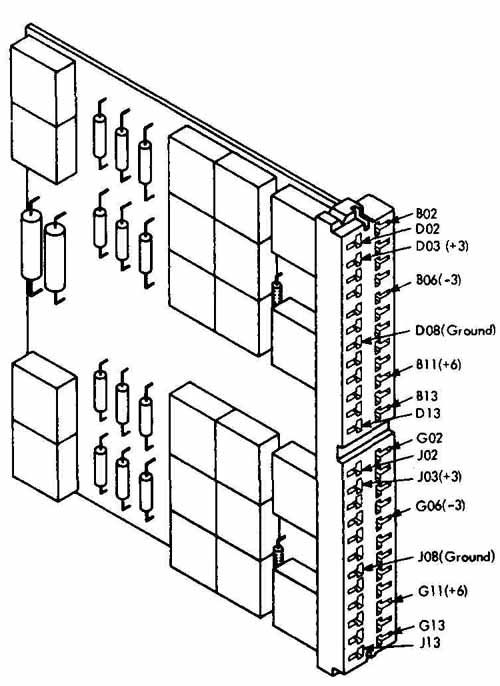
FIG. 10 Isometric pictorial of a PCB showing contact assignments.
Starting at point A, the three axes are drawn first, one vertical, one 30° receding to the right, and one at 30° receding to the left. The edges of the box are constructed from the height, width, and depth dimensions transferred from (3). Remember, in an isometric drawing the dimensions are not foreshortened; there fore, each measurement is taken full scale from the multiview projection (or directly from the object), provided that the distance is on or parallel to one of the axes. In isometric drawing, all lines parallel to or on one of the three axes are true length. This type of line is called an isometric line, and all lines that are not parallel to or on an axis are called nonisometric lines (inclined lines) and will not be true length when shown on the isometric drawing. Nonisometric lines must be established from their endpoints, which are located along isometric lines.
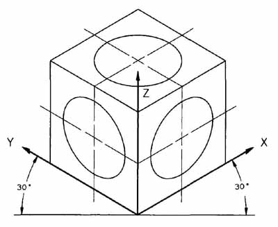
FIG. 11 Isometric axes.
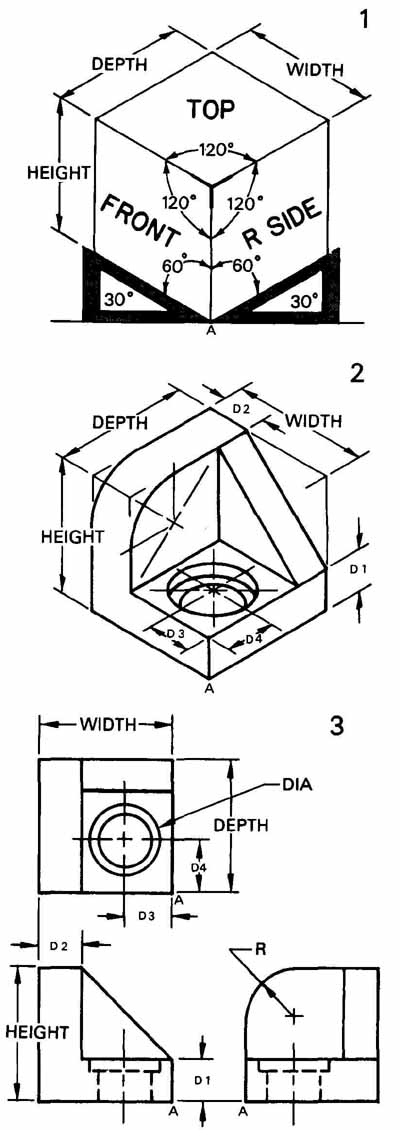
FIG. 12 Isometric construction with the glass box method.
After the object is boxed in, the remainder of the drawing is completed. Dividers (or a scale) are used to transfer each of the dimensions shown in (3) to the isometric view (2). All measurements are taken along lines that are parallel to or on the axes (along isometric lines). Dimension D1 is measured along the vertical axis, and dimensions D2, D3, and D4 are in the horizontal plane and are measured along or parallel to one of the corresponding receding axes as shown.
Hidden lines can be omitted in most pictorial illustrations unless required for clarification. Isometric circle and arc construction are covered later in the section.
Isometric Angles
The three major axes along an isometric box (or cube) are at 120 degree angles to one another. In reality, all lines of a cube are at 90° or are parallel to each other. Because of the distortion created by the isometric view of the box, few angles appear as true angles. Angles must be established by means of offset dimensions. Angles appear larger or smaller than true size on isometric drawings depending on their position in the view.
The rectangular plane in FIG. 13 has angles of 45° and 30°. These two angles must be constructed from offset dimensions along isometric lines using true length measurements from the orthographic view of the plane (.1).
In FIG. 13 the isometric plane (2) is boxed in with true length dimensions A and B along the isometric axes. The 30° angle was constructed by transferring dimension C. The 45-degree angle was drawn by transferring offset dimensions E and F to establish the endpoints. The points were then connected, completing the figure. Note that D and H are non-isometric lines and appear distorted, as do both angles. Neither is true size.
The dimensional multiview projection of the integrated circuit shown in FIG. 14 was used to construct its isometric pictorial in FIG. 15. The part was boxed in and then each feature was carved out. ( FIG. 7 shows two examples of similar integrated circuits pictorially represented in a technical manual.)
Isometric Circles
All circles and circular arcs on isometric drawings appear elliptical. A variety of methods is available for isometric ellipse construction: template, trammel, four center, and point plotting, to name a few. In general, a template should be used whenever the size of the ellipse can be matched with available equipment. FIG. 16 shows a true isometric projection hole template. FIG. 17 is an ellipse template with typical angle ellipses: 20°, 30° 40°, and 50°.
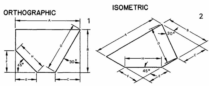
FIG. 13 Angle construction in isometric projection.
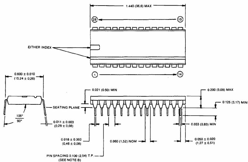
FIG. 14 Multiview-dimensioned drawing of an integrated circuit. (Courtesy
Ernie Schweinzger & Assoc.)
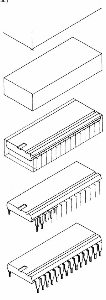
FIG. 15 Construction steps for isometric pictorial of integrated circuit
shown in FIG. 14. (Courtesy Ernie Schweinzger & Assoc.)
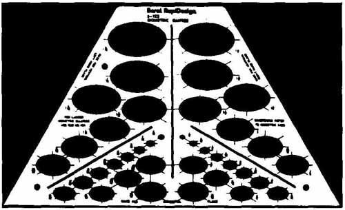
FIG. 16 Isometric ellipse template. (Berol RapiDesign)
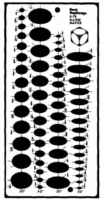
FIG. 17 Ellipse template. (Berol RapiDesign)
The trammel and point plotting methods are the most accurate, but time-consuming, procedures for constructing circles and arcs in isometric when templates are not available. These two methods should only be used when the other methods are inadequate for a particular project.
The four-center method shown in Fig. 18 does not create a perfect ellipse, but is accurate enough for most purposes. This method can be used to draw circles or portions of circles on any isometric face (plane), as shown in FIG. 19. The following steps describe the construction of an isometric ellipse ( FIG. 18):
1. Draw lines DA and DC along the two receding axes (at 30°). Line AB is parallel to DC, and line CB is parallel to AD.
2. Draw construction lines from point D perpendicular to line AB at its midpoint and perpendicular to line CB at its midpoint.
3. Repeat step 2 using point B and lines AD and CD.
4. Use point D and point B to swing arcs R1. Arc R2 originates at the intersection of the construction lines for both sides of the ellipse.
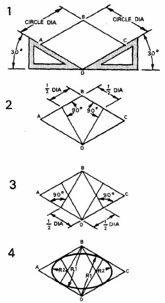
FIG. 18 Isometric circle construction (ellipse), four-center method.
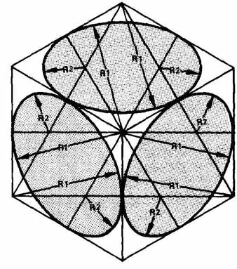
FIG. 19 Isometric circle construction (ellipse) on an isometric cube.
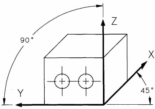
FIG. 20 Oblique projection, standard position.
Circles, arcs, or curves that do not lie in isometric planes must be plotted with offset dimensions. This procedure requires that a series of points be established along the curved outline in the orthographic view. Offset dimensions for these points are transferred to the isometric drawing and are laid off along isometric lines. In actual industry practice, templates are used whenever and wherever possible.
OBLIQUE PROJECTION
Oblique drawings are similar to isometric drawings; however, they are produced from parallel projectors that are not perpendicular to the projection plane. The primary difference lies in the use of only one receding axis and the ability to draw one surface as true shape and size in the front plane. In FIG. 20, the three axes are vertical Z, horizontal Y, and receding X. In oblique projection the front face of the part is placed parallel to the image plane; therefore, the Z and Y axes are at 90° and are parallel to the projection (image) plane, as shown in FIG. 20. The other two faces of the part are on receding (oblique) planes. The front face of the block and the diameter of the hole are drawn true shape and size, and all measurements on this front face are true length. The most commonly used angle for the receding axis is 45°.
There are two basic categories of oblique projection, cavalier and cabinet, as shown in FIG. 21. In a cavalier projection (1), receding lines are not foreshortened, but are drawn full scale. In a cabinet projection (2) the receding lines have been foreshortened one-half their original length (½ scale). The receding axis can be any convenient angle between 10 and 89°. The choice of receding angle is determined by the shape of the object and the most descriptive view orientation.
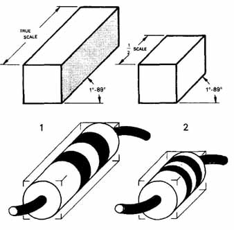
FIG. 21 Oblique projection: (1) cavalier; (2) cabinet.
Objects that are drawn with oblique projection should be oriented so that the surface with curved lines lies in the front plane bounded by the axes that are at 90°. This orientation lessens drawing time since all surfaces that lie on the front plane or that are parallel to it are drawn true shape and size. Circles and arcs are therefore true projections.
Oblique projection is extremely useful for drawings composed of multiple and parallel curved, or irregular, outlines. The longest or most irregular surface should be the front of the projection wherever possible. This is a definite advantage when the surface is composed of curved lines, as in FIG. 22. Here, successive circular outlines and surfaces are not distorted since they are all parallel with the front plane.
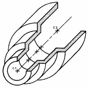
FIG. 22 Oblique projection, circles.
The face of a part that has a curved outline should be chosen as the front face (the face lying in or parallel to the front plane), as in Fig. 5 23. In this figure a set of steps is provided for pictorially representing the object. This drawing was completed with cavalier projection, so all dimensions (parallel to an axis, even on the receding faces) are true length and can be transferred from the multiview projection in FIG. 23:
1. Each dimension of this orthographic projection can be transferred true length to the oblique view.
2. Start by drawing the front face of the object using the height (H) and width (W) dimension. Then deter mine the receding angle (45° was used here). Transfer the depth (D) dimension along the receding axis and block in the outline of the object. Use dimension A to establish the top of the plane surface.
3. Use dimensions B and C to locate the circular shape. Dimension C is the diameter of the circle.
4. Complete the object by transferring offset dimensions E and F to establish the angled surface. Draw a true circle (half-circle) using dimension C as the diameter. Note that the circular shapes are parallel to the front plane and are therefore true shape. For circles and arcs that appear on oblique faces, the oblique four-center method or template must be used.
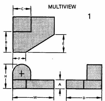
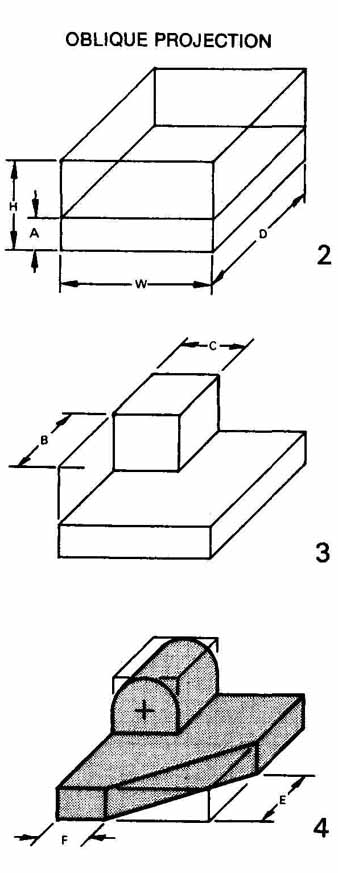
FIG. 23 Oblique construction with glass box method and dimensions
transferred from multiview drawing.
Note that the construction process for slanted, inclined lines and planes is similar to that of isometric drawings. Locate their endpoints along lines that are parallel to one of the axes. For slanted surfaces, locate both ends of the surface and connect the points.
PERSPECTIVE PROJECTION
Perspective projection is used to provide illustrations that approximate how a particular object looks to the human eye or as a camera would record the object on film. Since a perspective drawing approximates how an object really looks, it is not dimensionally correct. Many lines and planes on perspective drawings cannot be scaled since they are not drawn true length or true shape. Because of this distortion, perspective drawings are seldom found in engineering or design work. Technical illustrations for advertisements, sales catalogs, technical manuals, and architectural renderings make extensive use of this form of pictorial projection.
All lines in perspective drawings converge at one, two, or three points on the horizon (vanishing points) and therefore are not parallel, as in oblique and axonometric projections.
Three basic categories exist in perspective projection: parallel, angular, and oblique. Parallel perspectives (one-point perspectives) are constructed similar to oblique drawings since the front face of the object is parallel to the projection plane, but all receding lines converge at one point. Angular perspectives are drawn with two vanishing points and are called two-point perspectives. Oblique perspectives are three-point perspectives since they have three vanishing points ( FIG. 24). For further information regarding perspective projection refer to one of the many technical drawing and illustration texts that are available.
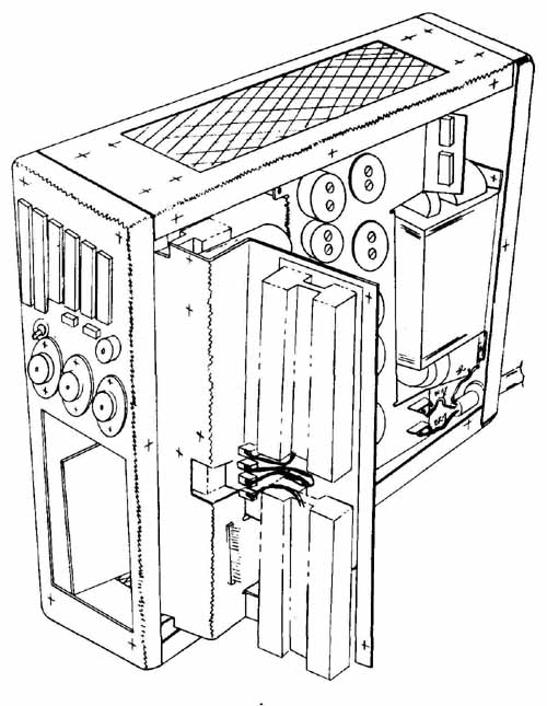
FIG. 24 Three-point perspective.
APPLICATIONS FOR PICTORIALS
The most common uses of pictorial illustrations in the electronics field are for assemblies and exploded views. An assembly drawing may be needed to show the construction sequence, to visually depict assembly instructions, or to identify parts in technical, user, and service manuals. Exploded views are widely used to show an assembly procedure ( FIG. 25).
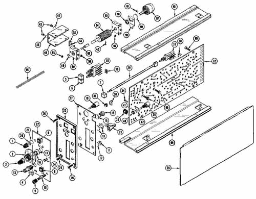
FIG. 25 Exploded assembly.
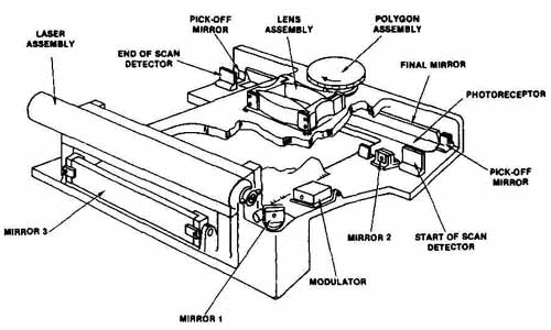
FIG. 26 Output Scanner Optical System. (Xerox Corp.)
A photograph with overlay ballooning may be sufficient for parts identification, but a pictorial drawing is far more descriptive. The Output Scanner Optical system shown in the parts identification pictorial in FIG. 26 could be adequately communicated with a photo graph and overlay identification if only its exterior con figuration and parts were to be presented. Note that the use of a photograph and line drawing in combination is called photo-drafting or a photographic pictorial. Since the modulator, mirror 2. photoreceptor, and other important parts need to be identified in this figure. a pictorial drawing with cutaway procedure was used so that the interior of the system could be viewed. Notice that hidden lines and centerlines have been left out in this and most of the pictorials shown throughout the text. Hidden lines are shown only where they are absolutely needed for identification. Unneeded hidden lines and centerlines only confuse the user of the drawing. Center lines are shown where they are needed to define symmetry or for dimensioning.
Exploded views are drawn with any of the previously mentioned pictorial projection techniques. Isometric exploded projections are the easiest to construct. Although a photograph shows the item in its entirety, an exploded pictorial provides a view where each individual part can be called out (ballooned) and shown in its relation to all other parts of the item.
Pictorial rendition allows for the identification of each part and how it is connected or assembled. Figures 27 and 28 show a photograph and the exploded assembly of the trackman mouse.
(coming soon) FIG. 27 Trackman mouse. (Logitech, Inc.)
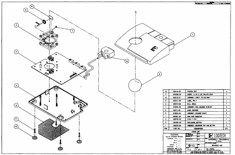
FIG. 28 Exploded assembly pictorial of trackman mouse. (Logitech, Inc.)
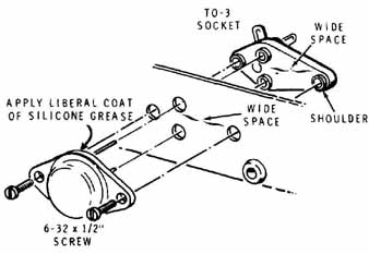
FIG. 29 Assembly pictorial. ( HEATH COMPANY)
Each part of an exploded view is normally drawn separately and then positioned along its axis or center line, as in FIG. 29, where the component and the socket are shown aligned with the centerlines that correspond to the screws and holes. The individual parts must be sufficiently separated to show all the individual items and their relationship to one another in the assembly.
FIG. 30 shows a variety of transistor and IC socket outlines drawn in pictorial form. Vertical unidirectional lettering was used to dimension these drawings.
In FIG. 31 the cage side wall plate uses the aligned method of dimensioning. The unidirectional lettering is constructed along horizontal guidelines and is the easiest to letter or place (if phototypeset). The aligned method requires that all characters be formed so that they lie on the plane of the isometric face in which they fall. Guidelines for aligned freehand lettering are drawn parallel to the dimension line. Thus, all lettering is aligned with the dimension lines. The vertical lines of all characters are aligned with (parallel to) the extension lines.
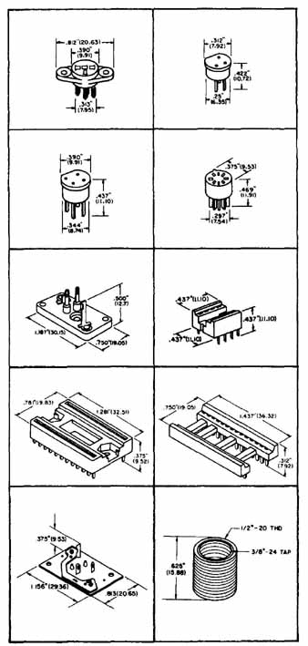
FIG. 30 Pictorial drawings of transistor and integrated socket outlines.
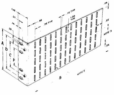
FIG. 31 Pictorial drawing of cage side walls, including aligned dimensions.
(Courtesy Vector Electronic Co., Inc.)
REVIEW QUESTIONS
1. A pictorial drawing normally shows ( ) views.
a. one c. three
b. two d. four
2. A cabinet drawing is a form of ( ) drawing.
a. perspective c. multiview
b. oblique d. orthographic
3. The primary difference between cabinet and cavalier drawings is that the depth axis for cabinet drawings is foreshortened:
a.½ c.3/8
b.¾ d.¼
4. The angle between axes of an isometric drawing is:
a. 90° c. 60°
b. 180° d. 120°
5. Which face of an object should be placed in the front plane of an oblique drawing?
a. front c. longest
b. curved d. side
6. The advantage of ( ) drawing lies in the ability to vary the degree of axis orientation.
a. isometric c. oblique
b. perspective d. multiview
7. True isometric projections require that the receding dimensions be set off:
a. full scale c. ¾ scale
b. half-scale d. with an isometric scale
8. The main principle of ( ) drawing is that all lines tend to meet at one or two points:
a. oblique c. perspective
b. isometric d. multiview
9. Isometric means:
a. equal angles c. 30° angles
b. three axes d. equal sides
10. Vertical lines are ( ) lines when transferred to the isometric drawing:
a. slanted c. true length
b. inclined d. vertical
11. After the axes are established on an axonometric or oblique drawing, the next step involves:
a. boxing in c. scaling
b. transferring d. inking
12. The common receding axis angle for an oblique drawing is:
a. 30° c. .60°
b. 45° d. 90°
13. The right and the left isometric axes of an isometric drawing are drawn 30° in the horizontal. How many degrees are they from the vertical axis?
a. 30° c. 45°
b. 120° d. 60°
14. Which form of 3-plane pictorial projection is best suited for objects with circular faces?
a. perspective c. oblique
b. isometric d. orthographic
15. Nonisometric lines are not:
a. true length c. inclined
b. angled d. foreshortened
16. The primary use for pictorial drawings is for:
a. engineering sketches c. manuals
b. design drawings d. production
17. Which type of pictorial is the easiest to dimension?
a. multiview c. perspective
b. orthographic d. isometric
18. Which type of line is not usually shown on a pictorial drawing?
a. inclined c. dimension
b. hidden d. centerline
19. A(n) ( ) pictorial is used to show how parts of an assembly are related.
a. blow-up c. expanded
b. inset d. exploded
20. Briefly define the following terms:
- oblique
- isometric drawing
- isometric line
- perspective
- scaled
- cabinet
- 3-plane pictorial
- cavalier
- axonometric drawings
- nonisometric line
- exploded view
- isometric ellipse
- isometric projection
- unidirectional lettering
PROBLEMS
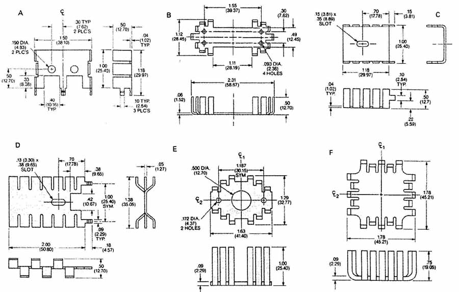
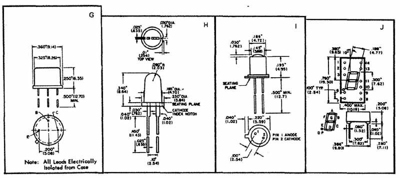
1 (A—J) Your instructor will assign the item, scale, and projection technique as required. Parts can be scaled from the drawings or dimensions can be used. A size sheets should be used.
PROBLEM 1 Heat dissipators and component outlines.
2 (A—M) Your instructor will assign the item, scale, and projection technique as required. Parts can be scaled from the drawings or dimensions can be used. A size sheets should be used.
PROBLEM 2 Component outlines.
3. Draw a pictorial (isometric) of the bracket.
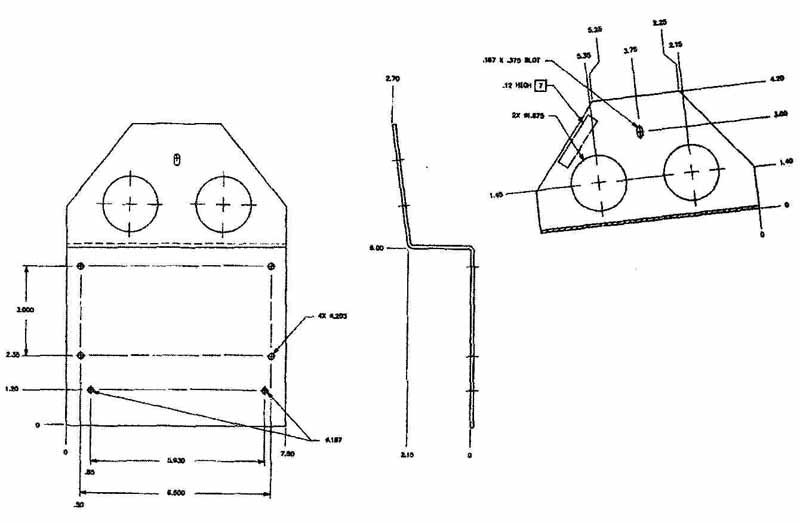
PROBLEM 3
4. Your instructor may assign projects to be completed as pictorials from the art in Sections 4 and 19.