AMAZON multi-meters discounts AMAZON oscilloscope discounts
INTRODUCTION
All forms of engineering and technical work require that a two-dimensional surface (paper) be used to communicate ideas and give the physical description of shapes. Here, projections have been divided into two basic categories: pictorial and multiview. This simple division separates single-view projections (oblique, perspective, and isometric) from multiview projections (orthographic). Pictorial projections are covered in Section 5.
Division of types based on whether the drawing is a one or multiview projection separates projection types into those used for engineering working drawings (orthographic/multiview) and those used for display (technical illustration, manual preparation).
Electronic drawings for production, manufacturing, and assembly use multiview orthographic projection al most exclusively, except where a pictorial projection is needed to explain particular aspects of a design.
In FIG. 1, the angle block shows each of four projection types with the same scale. This figure illustrates the difference between the types of projections. It also points out some of their shortcomings.
Pictorial projections are single-view drawings that do not lend themselves to the communication of engineering data except as rough sketches of preliminary ideas. Perspective projections are constructed with projecting lines that converge at a point; therefore, they do not show the true dimensions of a part, though this method provides the most lifelike appearance. The oblique method distorts when a part’s depth becomes too great. The isometric method uses full-scale dimensions for all lines that are vertical or parallel to the axes (receding at 30 degree). It is therefore more useful for engineering sketching.
Multiview drawings, because they show the part in more than one view, are not lifelike. This, however, is their only major drawback. Multiview projection presents the part’s top, front, and side in related adjacent views. All dimensions are drawn to a predetermined scale, and the three basic views can be used to project any number of needed auxiliary views in order to solve for or establish engineering data. An auxiliary view is any projection of a part other than one of the six principal views: front, top, right side, left side, back, and bottom.
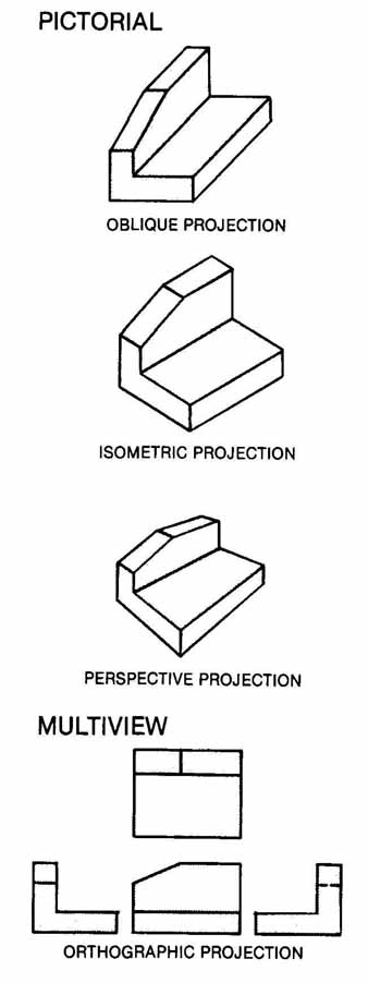
FIG. 1 Types of projections. PICTORIAL PERSPECTIVE PROJECTION; MULTI VIEW:
ORTHOGRAPHIC PROJECTION
MULTI VIEW PROJECTION
Multiview orthographic projection is the primary means of graphic communication used in engineering work. FIG. 2 shows a multiview drawing that conveys
ideas, dimensions, shapes, and procedures for manufacturing a sheet metal part for electronic equipment. Multiview projection completely describes an object’s shape and dimensions in two or more views that are normally projected at 90 degree angles to each other, or at specified angles for auxiliary views.
With the widespread use of computer-aided design (CAD), computers are now being used for many projects. This new medium eliminates hand-drawn linework and lettering but still requires knowledge of multiview projection. Knowledge of engineering projection methods and dimensioning conventions is essential regardless of the method used: CAD or manual.
Multiview drawing is the use of orthographic projection to solve for advanced technical data involving the spatial relationship of points, lines, planes, or solid shapes. There are two primary means of making orthographic projections: the normal method and the glass box method. In the normal or natural method the part is viewed perpendicular to each of its three primary surfaces.
In the glass box method the user must imagine that the part, with its points, lines, planes, and solid shapes, is enclosed in a transparent box. A view of the part is established on its corresponding glass box surface or plane by perpendicular projectors originating at each point of the part and extending to the box surface, as shown in FIG. 3. This box is hinged so that it can be unfolded onto one flat plane (the paper).
In the glass box method, all six sides are revolved outward so that they are in the plane of the paper. With the exception of the back plane, all are hinged to the front plane. The back plane is normally revolved from the left side view. Each plane is perpendicular to its adjacent plane and parallel to the plane across from it before it is revolved around its hinge line. A hinge line is the line of intersection between any adjacent image plane, including principal and auxiliary views.
The left side, front, right side, and back are all elevation views. Each is a vertical plane. In these views the height dimension, elevation, top, and bottom can be determined and dimensioned.
The top and bottom planes are in the horizontal plane. The depth dimension, width dimension, front, and back can be established in these two horizontal planes.
In the United States the six principal views of an object, or the glass box, are normally drawn in third angle orthographic projection. In third angle projection the line of sight goes through the image plane to the part, as shown in Figs. 3 and 4. To obtain each view of the object, the drafter must assume that the part is projected back (along the lines of sight) to the image plane. Projectors are used to illustrate this projection from the part to where they intersect the image.
The lines of sight represent the direction from which the part is viewed, as illustrated in FIG. 3. The vertical lines of sight (A) and horizontal lines of sight (B) are assumed to originate at infinity. They are always perpendicular to the image plane, represented by the surfaces of the glass box (top, front, and right side). Projection lines (C) connect the same point on the image plane from view to view, always at right angles. Remember that the part could be any graphical form.
A point is projected on the image plane where its projector or line of sight pierces that image plane. Point 1 in FIG. 3, which represents a corner of the part, has been projected onto the three primary image planes.
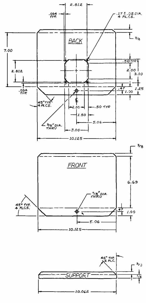
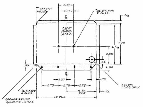
FIG. 2 Sheet metal enclosure.
The Glass Box and Hinge Lines
Each image plane or surface of the glass box is connected at right angles to an adjacent view. The top view is hinged to the front view, as is the right side view. These hinge lines are the intersection of the perpendicular image planes. Normally, hinge lines are not shown on technical drawings.
FIG. 4 (1) shows the part pictorially. In FIG. 4 (2), the part is enclosed in a glass box. The top image plane is shown being rotated about the line of intersection and the hinge line, which is between the top image plane and the front image plane. The side image plane is rotated about the hinge line, between the side and the front image planes.
FIG. 4 (3) shows the glass box opened into the plane of the paper. The front view is assumed to be stationary. Each required view is then rotated until it is in the same plane as the front view.
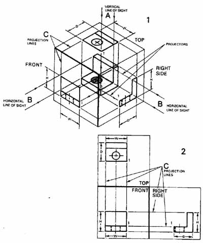
FIG. 3 Multiview projection.
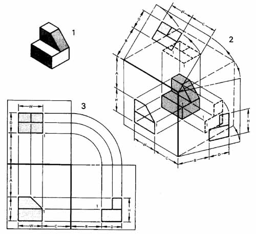
FIG. 4 The glass box and multiview projection.
Point 1 is located on the corner of the object and is shown projected onto each of the three image planes.
The line of sight is at right angles to the projection plane. To properly visualize this, you must imagine standing in front of the part with the image plane between you and the part. Your position will change for every view of the object so that your line of sight is at a right angle to each image plane.
Auxiliary Views
Any view that lies in a projection plane other than the horizontal, frontal, or profile plane is considered an auxiliary view. This type of projection is essential when the part to be drawn is complex and has a variety of lines or planes that are not parallel to one of the three principal planes.
Primary auxiliary views are projected from one of the six principal views. A primary auxiliary view is perpendicular to one of the three principal planes and is inclined to the other two. Secondary auxiliary views are projected from a primary auxiliary view and are inclined to all three principal planes of projection. Successive auxiliary views are projected from secondary auxiliary views.
In industry, auxiliary views are used to describe the true configuration of a part and to give its dimensions in views that show inclined lines or planes true size. In most cases only partial auxiliary views are constructed.
Primary auxiliary views can be divided into three types: frontal (front), horizontal (top), and profile (side).
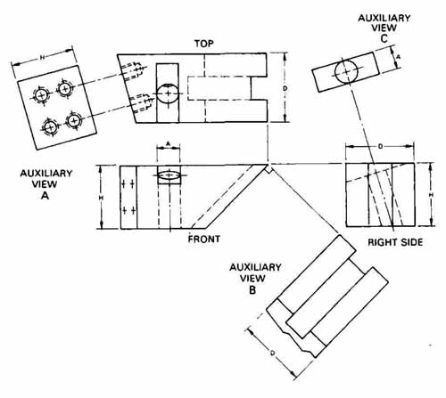
FIG. 5 Auxiliary views.
These three types are represented in FIG. 5, where auxiliary view A is projected from the top view, auxiliary view B is projected from the front view, and auxiliary view C is projected from the side view. Each auxiliary projection in this figure is a partial view, showing only the inclined surface as true shape. This is normal industry practice since the projection of the total part would add little to the understanding of the part’s configuration and might actually confuse the view. Hid den lines that fall behind the true shape surface in an auxiliary view are normally not drawn for the same reasons.
Besides being projected from one of the three principal views, each primary auxiliary view has common dimensions with at least one other principal view. The height (H) dimension in the front view is used to establish the H dimension in auxiliary view A. The depth (D) of the part can be found in the top and side views and is used to establish the D dimension in auxiliary view B.
Selection of Views
The proper selection of views and view orientation must take into account the part to be drawn and its natural or assembled position. The choice of additional views, after the top and front views are established, is deter mined by the configuration of the part and the minimum number of views necessary to describe it graphically and show its dimensions.
For cylindrical parts, only one view may be necessary, since the diameter dimensions describe width and depth but features along the length are dimensioned in the given view. This is called a one-view drawing. FIG. 6 shows a one-view drawing of a panel. The part is a thin sheet of metal and therefore does not require a second view since its depth or thickness is called out (specified).
A three-view drawing of a bracket is shown in FIG. 7. In most cases, engineering drawings require three or more views.
Sectioning
An imaginary cut taken through an object on a pre-established plane or planes perpendicular to the line of sight is called a section. Sectioning exposes the interior shape and dimensions of the part. If hidden lines in the exterior view do not adequately define the part, then a section should be taken for clarification. The exposed, cut portions and surfaces of the section are defined by section lines and cross-hatching, normally drawn at a 45° angle. Section lines are spaced according to the overall size of the sectioned surface and the expected reduction requirements. A distance of .12 in. (3.0 mm) between section lines can be used for most drawings. In some cases the material of the part is identified by a specific section symbol. The standard section cross-hatching for all types of materials uses evenly spaced parallel lines.
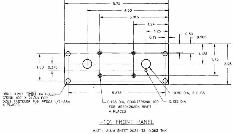
FIG. 6 Panel.
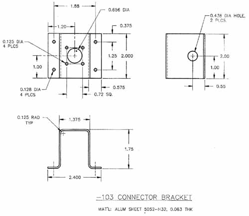
FIG. 7 Bracket.
The general section symbol used for all materials is the same as the cast iron symbol, or evenly spaced parallel lines (Figs. 8 and 9).
The cutting-plane line is shown on the view where the cutting plane appears as an edge ( FIG. 8). The ends of the cutting-plane line form a corner of 90 degree. These lines are terminated by arrowheads to show the direction of sight for viewing. In most cases, the section is defined by capital letters, A—A, B—B, C—C, and so on ( FIG. 8). Arrows on cutting-plane lines should be larger and of a different configuration than those used for dimension lines.
For simple sections or symmetrical parts, where the location of the section is obvious, the cutting-plane line may be omitted, for instance, where the adjacent view is the section: top view with front section view, front view with side sectioned view. Two or more mating parts must have section line angles at different degrees to differentiate the parts.
Solid round parts such as hardware (nuts, bolts, washers, rivets, shafts, pins) and other solid machine elements that have no internal construction are not shown sectioned even though the cutting plane passes through these features. They are more easily recognized by their exterior surfaces.
Sections that are taken longitudinally through webs, ribs, spokes, gear teeth, or similar solid elements should not show section lines even though the cutting plane passes through these elements.
A variety of section types is used on engineering drawings. In FIG. 8, sections A—A and B—B are removed sections. They are also partial sections. Section C—C is a full section. The detail of the memory pin in FIG. 9 makes use of partial sections E—E and F—F, detail sections B, C, and D, and enlarged sections taken from A—A.
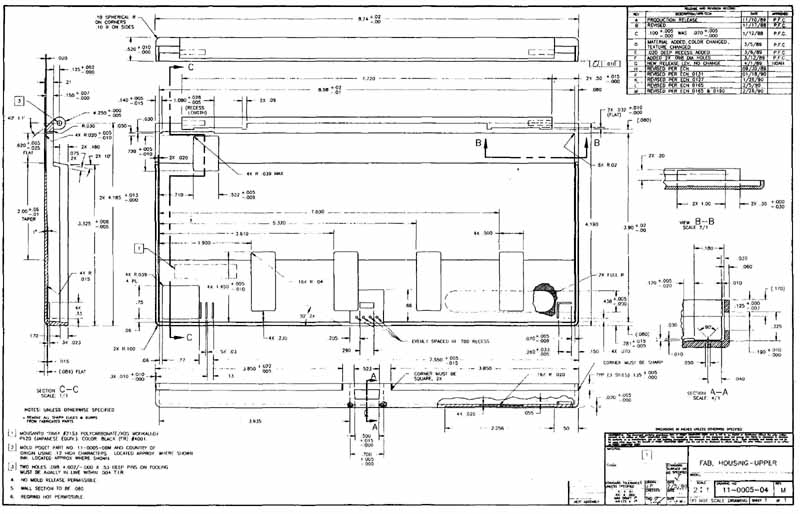
FIG. 8 Upper housing fabrication.
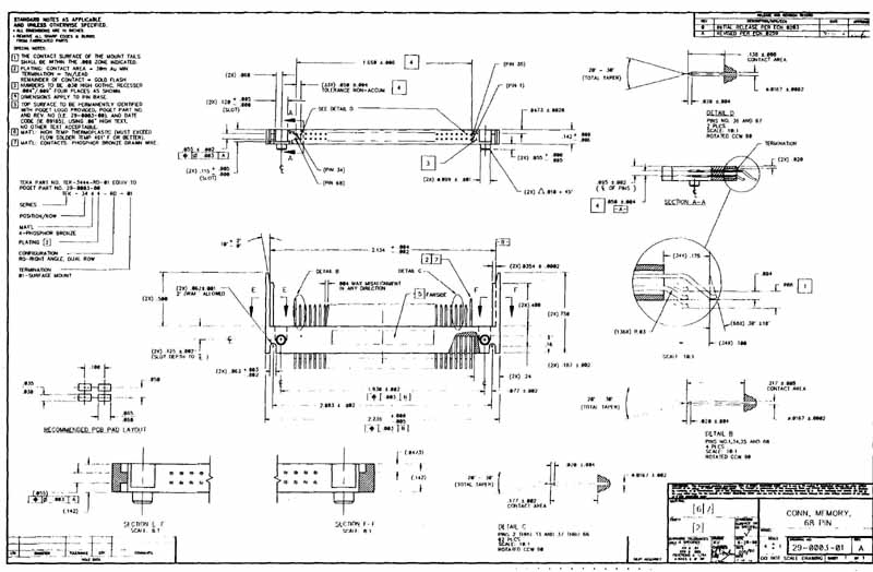
FIG. 9 Memory pin connector.
DIMENSIONING
A wide variety of electronic drawings requires dimensioning. Sheet metal details and developments for electronic equipment as well as cabinets, enclosures, and panels (Figs. 8 and 9) need extensive dimensioning. Printed circuit boards also require dimensioning for ac curate manufacturing and production.
CAD systems require that the dimensioning be placed and calculated by the drafter. In other words, you still have to know how to dimension the drawing.
Drawings should be dimensioned for the end product with dimensions and notes. Dimensions must be provided between points, lines, or surfaces that are functionally related to each other or control relationships of other parts.
Each dimension on a drawing (Figs. 8 and 9) has a tolerance, either implied or specified. A general tolerance specification is given in the title block, with specific tolerances provided with each appropriate dimension when required. Tolerances are discussed at the end of the section.
Units of Measurement, Linear Dimensions
For some drawings in the United States, linear dimensions are expressed in inches. When the metric system (SI units) is used, dimensions are expressed in millimeters or centimeters. In either system, dimensions should be shown only to as many decimal places as accuracy requires. Omit the inch or millimeter symbol unless there is a possibility that the dimension may be misunderstood. When U.S. customary units are used, fractions and decimals should not be mixed. (Seearch Google for: U.S. customary and metric equivalents.)
Dual dimensioning (including both U.S. customary and metric units) is sometimes used on drawings. The U.S. customary measurement is normally placed above the metric equivalent. The U.S. customary measurement is in decimal inches and the metric measurement is given in millimeters. The top measurement (or first measurement when placed on the same line) in dual dimensioning is always in the unit of measurement that was used in the design of the part..
Dimensioning Numerals
Whole numbers in the inch system are normally shown to at least one decimal place (1.0, 2.0, 3.0, etc.). This practice prevents dimensions from being lost on the drawing, a common occurrence when the number 1 is not accompanied by a decimal point and a zero: 1.0.
Common fraction dimensions are seldom used in the electronics industry. Before the adoption of the decimal inch, common fractions were used for subdivisions of the inch to specify nominal sizes and dimensions. Some firms still use this system, especially where the tolerance factor is relatively unimportant. Older company drawings also show this type of dimensioning.
A method of rounding off numbers has been adopted by ANSI (American National Standards Institute). A decimal value may be rounded off to a lesser number of places by the following procedure:
1. Where the digit to be dropped is less than 5, there is no change in the preceding digits.
Examples:
.47244 rounds to .4724
.1562 rounds to .156
.20312 rounds to .2031
.35433 rounds to .3543
2. Where the digit to be dropped is greater than 5, the preceding digit is increased by 1.
Examples:
.23437 rounds to .2344
.55118 rounds to .5512
.03937 rounds to .0394
.6406 rounds to .641
3. Where the digit to be dropped is 5, round the preceding digit to the nearest even number.
Examples:
.98425 rounds to .9842
.59055 rounds to .5906
.19685 rounds to .1968
.4375 rounds to .438
Drawings should be to a scale that allows the object to be easily read and accurately interpreted. Scales should remain constant within a given project where multiple drawings are needed. The choice of scale must take into account the maximum reduction required for the drawing. Scales should be stated in the title block:
1 :1 (full scale), ½ (half scale), ¼ (quarter scale), 1:5, 1:10, and so on.
When the detail on a drawing is too small, an enlarged scale can be used: 2: 1 (two times size), 5: 1, 10: 1, and so on. Printed circuit artwork is normally prepared at a 2:1 or 4:1 enlarged scale when manual drafting and taping methods are used.
In some cases more than one scale is used on a drawing, as when a portion of the drawing is blown up (enlarged). The predominate scale is to be shown in the scale area within the title block, and any other scales are placed under the appropriate view.
Dimensioning Elements
Dimension lines were introduced in Section 3. Dimensioning elements include leaders, dimension lines, extension lines, and arrowheads. This section concentrates on the actual use and placement of these elements.
Leaders are used to point out a curved feature of a drawing or to reference a portion or surface of an object. In FIG. 10 the three most common uses of a leader are shown: to call out a hole diameter, to call out a radius, and to reference a surface or a part with a note. When a leader is used to dimension a circle or radius arc, it must point at or from the center of the circle or radius.
Leaders and their accompanying notes and callouts should be kept to the outside of dimension lines and away from the part being dimensioned. It is poor practice to put a note or dimension on the part itself. Care should be taken not to cross leader lines, although leaders can cross object, dimension, and extension lines.
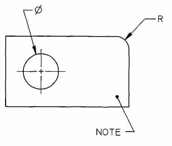
FIG. 10 Leaders.
Spacing Dimensions
Dimension lines should be positioned as shown in FIG. 11. The minimum distance from the first dimension to the part outline should be .375 in. (10 mm), and the minimum spacing between parallel dimensions should be .25 in. (6mm). Note that .50 in. (12 mm) from the part and .375 to .50 in. (10 to 12mm) between dimensions are suggested for large drawings and those that need to be greatly reduced. The larger sizes should be used whenever there is enough room.
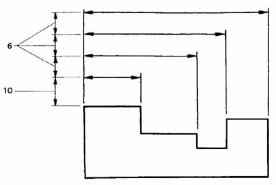
FIG. 11 Spacing dimension lines.
Extension lines should start about .06 in. (1.3 mm) from the part and end approximately .12 in. (2.5 mm) beyond the dimension line and arrowhead.
All dimensions are drawn parallel to the direction of measurement. Numerals should be staggered when there are a number of parallel dimensions, as in Fig. 12. For electromechanical drawings the dimension line should be broken for insertion of the measurement (numerals). Centerlines can be used as extension lines, as in FIG. 13, but must not be used as dimension lines. In most cases the lines of a part should not be used as extension lines and never as dimension lines.
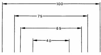
FIG. 12 Staggered dimensions.
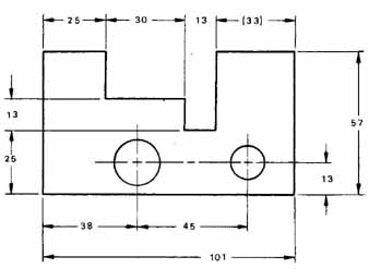
FIG. 13 Unidirectional dimension alignment and grouping.
Grouping Dimensions and Orienting Numerals
Numerals that are placed in a position lined up with the dimension line are called aligned dimensions. In aligned dimensions, horizontal dimensions should always be readable from the bottom and vertical dimensions, from the right side of the drawing. Unidirectional dimensioning places the numerals parallel with the bottom of the drawing (and therefore readable from the bottom of the drawing), as in FIG. 13. This system is preferred since the drawing may be read and lettered without being turned.
It may be desirable to include all the dimensions for reference information or checking purposes. In these cases, a nontoleranced reference dimension is used. In FIG. 13, the referenced dimension is placed within parentheses (33); however, this measurement is not necessary for part manufacturing.
Application of Dimension Elements
Size and location dimensions may be given either as linear distances or as angles. Angular dimensions should be expressed in degrees, minutes, and seconds or as decimal equivalents of the angle, as in FIG. 14: 20.10°. When expressing angular dimensions, use symbols for degrees, minutes, and seconds on the drawing. Where angles are less than 1 degree, precede the minute by 0°. Place angular dimensions to read horizon tally with no dash between degrees and minutes. The angle may sometimes be given in degrees and decimal parts of a degree. Whenever possible, avoid angle dimensions by locating the endpoints of inclined lines and planes.
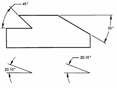
FIG. 14 Angular dimensions.
The dimension line for an angle is drawn as an arc from a center at the intersection of the sides of the angle. A variety of methods can be used to dimension angles, as shown in FIG. 14, depending on the avail able space.
Dimensioning Arcs
The dimension line for any radius should always be drawn as a radial line at an angle, as shown in Fin. 15. Do not use hori2ontal or vertical dimension lines when dimensioning arcs.
Sometimes the center of an arc is moved on a drawing either because there is a break or because the center lies outside the drawing paper. Then the new position is on a centerline of the arc, and the newly located false center leads to a staggered dimension, as in FIG. 15. The portion of the dimension line touching the arc should be a radial line drawn from the true center, whereas the staggered dimension is drawn parallel to the first radial line. In other words, when the center of an arc lies outside the limits of the drawing, the center is moved closer along a centerline of the arc, and the dimension line is jogged.
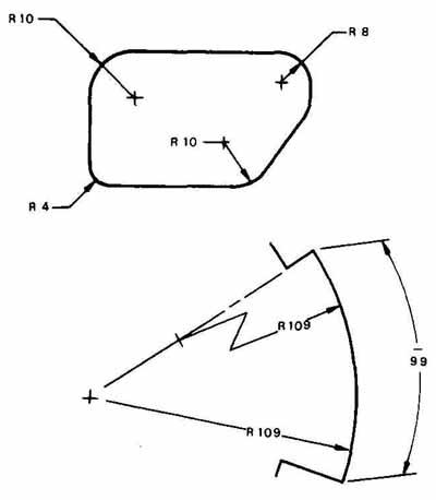
FIG. 15 Dimensions for radii and arcs.
The dimension of a radius is preceded or followed by the letter R (or in some cases RAD) when U.S. customary units are used. It is always preceded by an R when metric units are used, as in FIG. 15.
Actual arc lengths are dimensioned as in FIG. 15, where the 99-mm measurement is the arc length.
Dimensioning Slots
Slotted holes are found on a variety of electronic sheet metal drawings. Slots may be dimensioned in a number of ways. In FIG. 16, three variations are shown. Method 1 shows the slot’s centerlines located from an edge of the part and between centers. The slot width is also given as an R (radius) pointing to the end of the slot arc. The R .is normally accompanied by the note 2 PLACES.
Method 2 uses a leader and a note stating the out side dimensions of the slot, 13 X 50 in. An R callout is also included. The slot can also be located from the part’s edges (as in the third example), or its centerlines can be located from two controlling edges.
Method 3 shows dimensions of the slot on the view, giving the overall length and width along with its location dimensions. A full R callout is provided as in the other methods. (Note that all dimensions in this figure are given as metric units.) FIG. 17 is an example of the third method of slot dimensioning. A slot can have arc, radii, and/or rectangular configurations. Use of a full radius (R) guarantees a semicircle instead of an arc at the end of the slot.
The choice of methods for dimensioning slots is determined by design factors and the required slot tolerance (fit). If something fits into the slot, accurate tolerance and dimensions must be given for the slot shape and location on the part. The first and third methods are recommended when accuracy is important. If the slot position and size need not be accurate, the second method can be applied, such as for air-vent slots and loose control-handle travel guides.
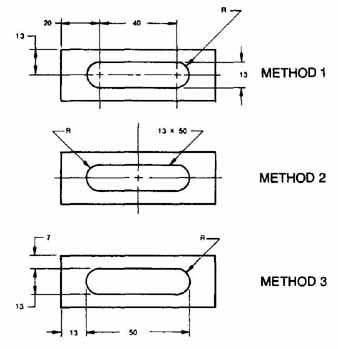
FIG. 16 Dimensions for slots.
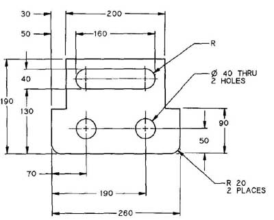
FIG. 17 Mounting panel.
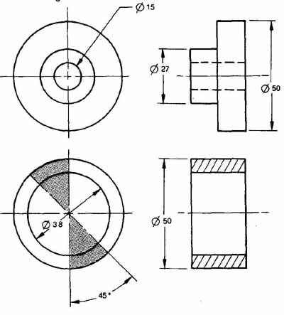
FIG. 18 Dimensioning diameters.
Diameters
Diameters can be dimensioned as shown in FIG. 18. All diameter dimensions should be preceded by the international symbol for diameter shown on this figure. The symbol should be a circle drawn the same size as the numerals, and it should have a 60 degree slanted line passing through its center. On some inch unit drawings the size of the diameter is called out with the abbreviation DIA after the numerals, for example, .375 DIA.
A number of different methods can be used to dimension diameters, depending on the size of the diameter and whether the diameter represents a hole or a solid shape. In general, holes should be called out with a leader and note. The leader must point toward the center of the circle.
A drafter can show the dimensions of a very large hole by drawing the dimension line at an angle through the diameter, as shown in FIG. 18 (lower left). The R 20 area within the shaded 45° section should be avoided when the dimension runs through the diameter.
Solid round shapes should be dimensioned on the side (edge) view, as in FIG. 18 (upper right, 027 and 050).
Chamfers
Chamfers may be specified by dimensions or notes. It is not necessary to use the word chamfer when the meaning is obvious. Where the chamfer is other than 45°, dimensions should always be used to show the direction of the slope. In FIG. 19 the methods for dimensioning inside and outside chamfers are provided. Note that a drafter can show chamfer dimensions by giving the chamfer angle and one leg, dimensioning both legs, or pointing to the chamfer and giving the angle and one leg as a callout. Inside dimensions can be dimensioned by giving the included angle (here 90°) and the largest diameter, or giving the chamfer angle (here 45°) and the largest diameter. The metric method of dimensioning chamfers is shown on this figure. For inch unit drawings the angle is sometimes given second and the leg first; for example, .25 X 45°. This method, however, is being replaced by the international method, as in ANSI Y14.5M.
Holes
As has been stated, you can show dimensions for holes by pointing to the diameter with a leader and giving a note containing the diameter’s size and, when necessary, the type. Where the depth of the hole is not obvious or not dimensioned, the word THRU, implying drill through, should follow the size specification.
In FIG. 20, several dimensioning methods for holes are provided. The most common method uses a note and leader. The method of drawing a dimension line through the diameter should be used only where the note method may get lost on the drawing, as when the object is complicated and the hole is large, measuring 1.50 in. (38.1 mm) and above. Dimensioning the hole by extending dimension lines from its edges (circumference), as in the mid-sized hole in FIG. 20 (far right), should be used for large-diameter holes only.
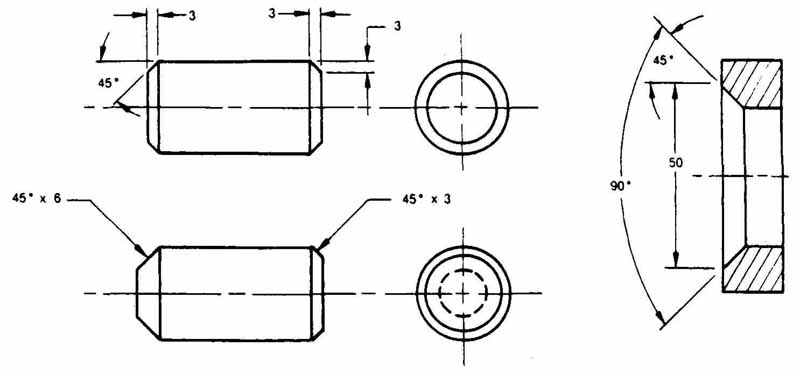
FIG. 19 Dimensioning chamfers.
Dimensioning holes in side views or section views should be used only when the hole cannot be adequately called out where it shows as a circle. The depth of the hole can be dimensioned in this view if it is not included in the note ( FIG. 20, bottom).
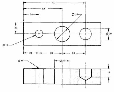
FIG. 20 Dimensioning holes.
Counterbore, Spotface, and Countersink
A counterbore (CBORE) is an enlarged hole, normally piloted from a smaller hole to maintain concentricity.
Counterbored holes are machined to a square seat at a specified depth, as shown in FIG. 21. The depth is normally established by dimensions showing the thickness of stock remaining under the counterbore rather than the depth of the counterbore, unless the piece is excessively thick. The depth can be called out within the hole note as the distance from the upper surface (beginning surface) to the bottom of the counterbore. Counterbores are used extensively for socket head screws, where the head of the screw must be flush with or below the surface.
A spotface (SF), shown in FIG. 21, is a method of cleaning up and squaring a surface like a cast metal part so that a screwhead will seat flush against the part.
Countersinking (CSK), FIG. 21, is a conical seat usually specified by the included angle and the diameter at the large end. Countersinking is used on holes where flathead screws need to be flush with the surface. Symbology on abbreviations can be used when calling out CBOREs, SFs, and CSKs. as in FIG. 21.
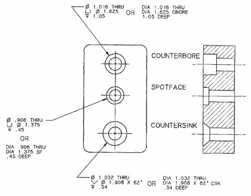
FIG. 21 Dimensioning counterbores, spotfaces, and countersinks.
THREADS
A simplified form of representing screw threads should be used to save drawing time when there is no possibility of confusion with other drawing details. The simplified symbol consists of straight lines, representing the major and minor diameters of screw threads.
The following thread classifications apply to non metric threads. When using metric units, consult the appropriate standard for proper specifications. Screw threads are classified in series according to the number of threads applied to a specific diameter. Unified (UN) thread is the standard type of thread for the United States. The UN thread series is designated as follows:
- Coarse Thread
- Fine Thread
- Extra Fine Thread
- Constant Pitch Thread
- Special Thread
When specifying screw threads, give the nominal major diameter first, followed by the number of threads per inch and the series designation. Then give the class of fit between positive and negative threads, followed by an A for positive threads and a B for negative threads. For tapped holes, however, the complete note contains the tap drill diameter and depth of hole, followed by the thread specification and the length of the tapped threads. All threads are assumed to be right hand un less left hand is specified by LH following the class. A few examples of screw thread notations are presented next:
- .190—32 UNF—2A or #10—32 UNF—2A
- .250-20 UNC-2A or ¼-20 UNC-2A
- 2.000—16 UN—2A
- 2.500—10 UNS—2A
For specifying the drill and tapping requirements of a hole, give the tap drill size, its depth, the thread specification, and the depth of threads, as in the examples shown here:
-- .312 DIA, 1.25 DEEP .374-16 UNC-2B or %-16 UNC-2B .88 DEEP
-- .422 DIA, 1.50 DEEP
.500-13 UNC-2B L.H. or ½-13 UNC-2B L.H.
1.12 DEEP
DIMENSIONING METHODS
There are five main methods of dimensioning: rectangular coordinate, datums, hole charts and tabular, center line, and continuous. This section describes each of these dimensioning methods.
Rectangular Coordinate and Datum Dimensioning
Rectangular coordinate dimensioning locates the features of an object by providing dimensions from two or three perpendicular planes or baselines. In general, this type of dimensioning either establishes datum lines (X and Y coordinate lines from which all dimensions are taken) ( FIG. 22) or it establishes the center lines of a symmetrical or circular shape. In FIG. 22, the X and Y coordinates are used as datum lines. Here, all dimensions are rectangularly positioned from the datum lines.
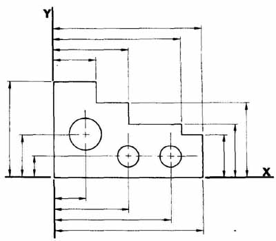
FIG. 22 Datum line dimensioning.
FIG. 23 uses the rectangular coordinate method. Circular cutouts and curved features are dimensioned by locating their centers from the left edge of the part. Hole patterns are established in separate details from the cutouts’ centers (details A through E).
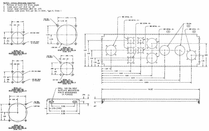
FIG. 23 Power distribution box.
Datum points, lines, or surfaces are features of a part that are assumed to be exact. They act as a baseline or reference for locating other features of the part. A feature selected to serve as a datum must be easily accessible and clearly identified. In most cases, datums are established as the far left and bottom line in a view, as shown in FIG. 22.
The vertical datum is designated as the Y axis and the horizontal datum as the X axis when the coordinate system is used. An artificial datum like a construction hole or line edge is sometimes machined in a part for manufacturing and checking purposes only. Printed circuit boards are normally provided with tooling holes for the same purpose. A datum surface must be more accurate than any locations measured from it. In some cases, it may be necessary to specify form tolerances for the datum surface to assure that locations can be accurately established.
FIG. 23 shows a detail of a power distribution box. The top view shows all dimensions taken from the lower left of the part. When dimension lines are eliminated and only measurements and extension lines are shown, this is called rectangular coordinate dimensioning without dimension lines ( FIG. 24).
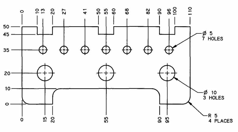
FIG. 24 Rectangular coordinate dimensioning without dimension lines.
Where parts must match or mate, the same hole centers must be used as the datum.
Where cumulative tolerances are excessive, dimensioning from a common base or datum will reduce the overall accumulation, but the tolerance on the distance between any two features, located with respect to a datum and not with respect to one another, will be equal to the sum of their tolerances. Therefore, if it is important functionally to control two features closely, the dimension should be given directly, as in the slot dimensions in FIG. 17. Here, the angle bracket was dimensioned from baselines except for the distance between the ends of each slot.
Hole Charts and Tabular Dimensioning
For complicated parts, or where a part has a multitude of holes in one or more surfaces, hole charts may be used to simplify the drawing. In hole charts, the surface of hole entry and each hole must be identified on the drawing.
The surface of hole entry must be identified with the names of the principal views. The order of these views for charting purposes is as follows:
1. Front
2. Top
3. Right
4. Left
5. Bottom
6. Rear
7. Auxiliary view (if used)
When using a hole chart, show the surface of entry of each hole, the symbol number that identifies each hole, and the amount each hole is used in this surface. The chart must also show the complete specification for each hole. This information is shown in the logical order of manufacture. Identical holes in a surface may be shown by a single symbol number or letter. Hole charts are commonly used for sheet metal details and drilling drawings for printed circuit boards.
On parts with very complex hole patterns, the locating dimensions for the holes may be shown in the chart as the X and Y positions in each view. This is called rectangular dimensioning in tabular form. These dimensions are usually placed on a chart to the right of the hole specifications. FIG. 25 shows an example of rectangular dimensioning without dimension lines, using a table.
In X and Y coordinate dimensioning, each hole must have a separate identifying symbol. A drafter can group holes by giving diameters the same size and the same letter symbols or by numbering them consecutively. The bottom left or bottom right corner of the front or primary view is usually selected as the zero point for labeling the X and Y axes. The Z axis is also provided for the depth dimension when only one view has holes in it. The direction of dimension measurement is always from a datum/base/coordinate line in the direction of the arrow. All holes are listed in the hole chart. Holes should be listed alphabetically starting from the largest with the letter A.
Another method of labeling holes for tabular dimensioning numbers each hole consecutively from number 1 without regard for size. If a numerical con trolled (NC) machine is to do the machining operation, holes of the same size should be grouped for easy programming.
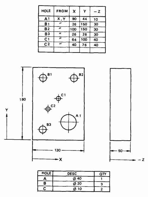
FIG. 25 Rectangular coordinate dimensioning in tabular form.
When the hole is to be completely through the part, THRU should be used as the Z dimension. Note that where more than one surface needs to have holes called out, X and Y axes can be established for each surface or view. The depth will need to be specified for each hole. The hole chart will also need to have the view noted.
Continuous Dimensioning
Continuous dimensioning is found on a variety of drawings. In this method dimensions are given from each other, or are progressive, as in FIG. 26, where dimensions along the part’s length are stacked or in a chain. Continuous dimensioning is also used where accurate tolerances are not given for the part features or where automated machining methods are not used, as in the fabrication of many sheet metal cabinets and enclosures for electronic equipment. When continuous dimensioning is used, it is important to remember that any errors in manufacturing will also be progressive, or accumulative. These errors will add up and could produce problems for mating or interchangeable parts. For additional details refer to Section 19.
TOLERANCE
Tolerance is the difference between the maximum and minimum limits. The tolerance of any dimension may be specified or implied. Implied tolerances mean that a dimension’s maximum and minimum sizes are con trolled by a company standard specification noted in the title block.
All dimensions on a drawing are subject to tolerance. When tolerances are not given with the dimension, the implied tolerances are specified in the title block. The following is an example of typical company specified tolerances:
General Surfaces
CUSTOMARY (inch) DIMENSIONS:
ONE-PLACE DECIMALS ± .04
TWO-PLACE DECIMALS ± .01
THREE-PLACE DECIMALS ± .005 METRIC (mm) DIMENSIONS:
ALL DIMENSIONS UNLESS
OTHERWISE SPECIFIED ± 0.25
ANGLES:
ANGLES that are machined on both surfaces will have an implied tolerance of ± 0.0 degree 30’.
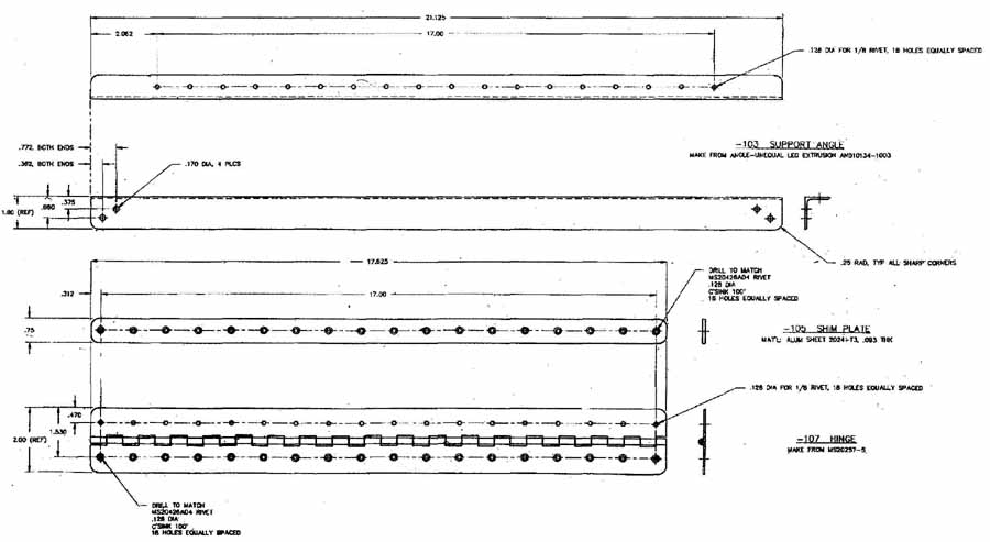
FIG. 26 Junction panel hinges.
Tolerance of size is specified on the drawing when the implied tolerance is not considered satisfactory, for example, tolerance for mating parts or for parts that must fit together when assembled. In FIG. 27 a few of the dimensions are given specific tolerances.
Two basic methods of tolerance dimensions are used: plus and minus tolerances and limit dimensioning. FIG. 27 is an example of plus and minus tolerance. Here each tolerance dimension is followed by a plus and a minus expression of tolerance, for example, 9.250 ± .005. This means that the feature should not exceed 9.255 and not be smaller than 9.245. Note that the plus and minus tolerance is also given for the dual metric unit dimension.
Limit dimensioning gives largest and smallest acceptable sizes for a particular feature of a drawing. In general, the high limit is placed above the low limit.
Tolerances and limits are complicated subjects, and this text cannot completely cover their many intricacies. The aspiring drafter or designer should consult ANSI Standard Y14.5M, Dimensioning and Tolerancing, for further discussion of tolerances.
Many companies use ANSI Y14.5M as their in- house drafting standard. But there are a considerable number of companies who have developed their own company standards and have not adopted ANSI methods.
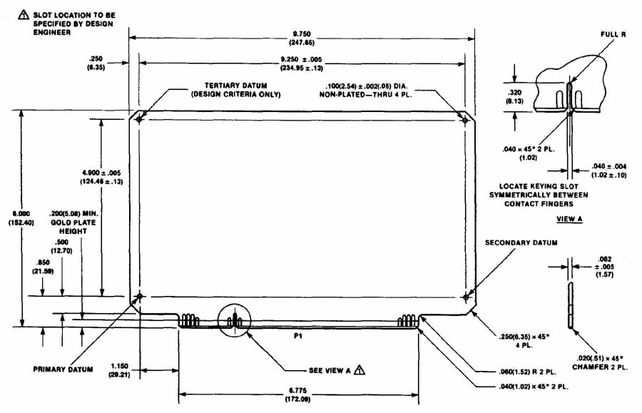
FIG. 27 Printed circuit board detail showing dimensions and tolerances. (Courtesy
Motorola, Inc., Semiconductor Products Sector)
REVIEW QUESTIONS
1. How far apart should parallel dimensions be?
2. Which type of projection is best for engineering work?
a. isometric c. multiview
b. oblique d. perspective
3. Section lines should be drawn at an angle of ( ) whenever possible.
4. Mating parts that are sectioned must have section lines that are at:
a. the same angles c. 30 and 45° b. different angles
5. True or false: Screws, bolts, and ribs should not be sectioned.
6 When dual dimensioning is used, the ( ) unit is normally on top.
a. metric c. U.S.
b. SI d. design
7. True or false: Angles are always given in degrees, minutes, and seconds.
8. True or false: A chamfer can be dimensioned if the drafter gives its angle and one leg.
9. True or false: The simplified thread method should be used when screw threads are drawn to simplify the process.
10. True or false: Continuous dimensioning is the most accurate of the various dimensioning methods.
11. Define the following terms:
- multiview
- CSK
- aligned dimensions
- glass box method
- unidirectional dimensioning
- auxiliary view
- tolerance
- sectioning
- plus and minus tolerance
- cutting plane
- limit dimensioning
- leaders
- dual dimensioning
- threads
- baseline
- coordinate dimensioning
- hole chart
- dimension lines
- angular dimensions
- extension lines
- third angle projection
- staggered dimension
- projector
- chamfer
- CBORE
- datum line
- SF
PROBLEMS
1. Draw the dual-in-line package 3 : 1 and dimension completely. Use dual dimensions. Letter notes in upper left-hand corner of drawing. Use an A sheet size.
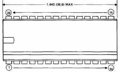
PROBLEM 1 IC outline.
2. Draw the mounting frame half-scale on a B size sheet. Dimension the entire project on the three primary views using datum lines. The frame is aluminum.
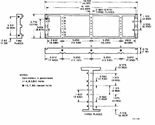
PROBLEM 2 Mounting frame.
3. Draw the mounting panel half-scale on a B size sheet. Dimension using the same system given. The panel is made of aluminum.
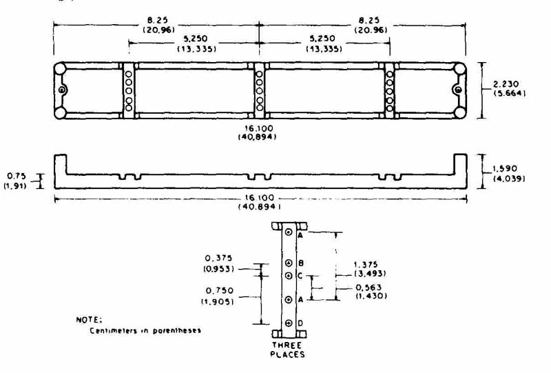
PROBLEM 3 Mounting panel.
4. Draw the connector block full scale on an A size sheet. Place the pin side view as a projection on the left. Dimension with the same system as shown.
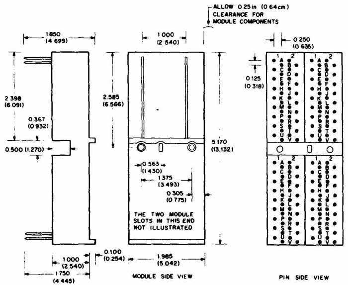
PROBLEM 4 Connector block.
5. Draw the component 3: 1. Use the same scale for the whole project. Put pin side view as a projection on the left. Show all sections and dimension completely. Use an A size sheet.
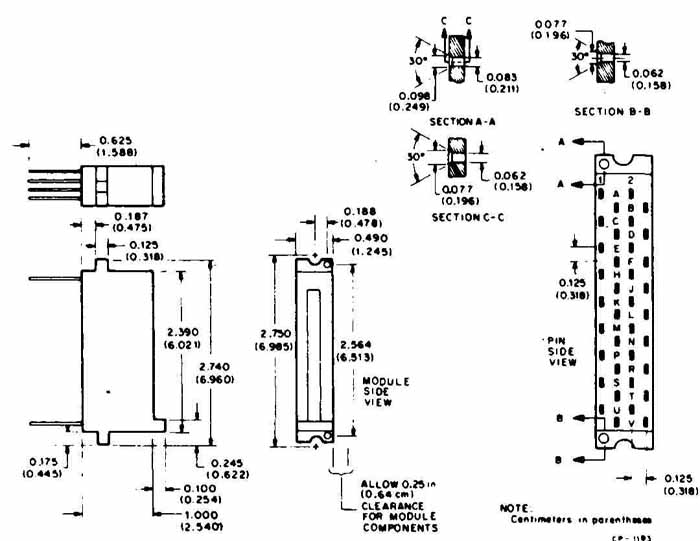
PROBLEM 5 Component.
6. Using a tabular hole chart, draw and dimension the socket panel. Number the holes sequentially. Draw the project half-scale on a B size sheet.
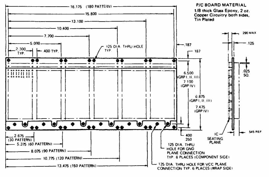
PROBLEM 6 Socket panel.
7. Draw and dimension the two brackets as separate projects. Draw the brackets three times size. The brackets are steel and will have an inside bend radius of 1/ in.
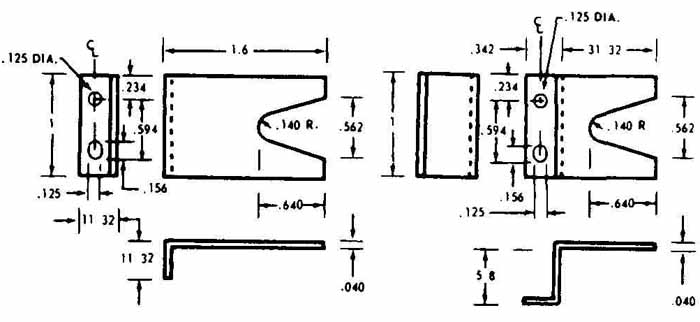
PROBLEM 7 Brackets for electronic equipment.
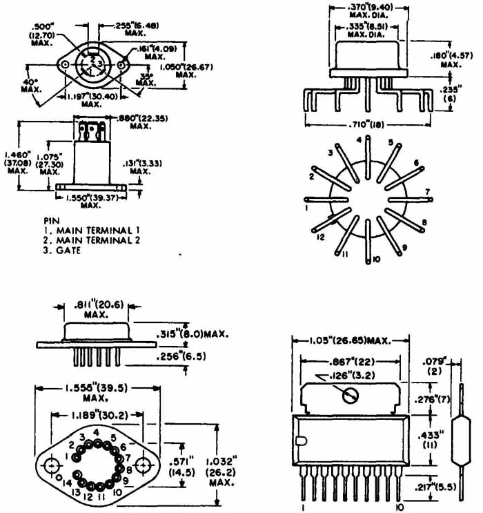
PROBLEM 8 Component outlines.
8. Sketch the component outlines 3: 1 on an A size sheet. Do not dimension.
9. Draw and dimension the front panel shown in FIG. 6. Use symbology for hole callouts.
10. Draw and dimension the three views of the connector bracket shown in FIG. 7. Use symbology for hole callouts.
11. Draw and dimension the upper housing fabrication shown in FIG. 8.
12 Draw and dimension the 68-pin memory connector shown in FIG. 9.
13. Draw and dimension the panel in FIG. 17.
14. Draw and dimension the power distribution box in FIG. 23.
15. Draw and dimension the junction panel hinges in FIG. 26.
16. Draw and dimension the PCB in FIG. 27.