AMAZON multi-meters discounts AMAZON oscilloscope discounts
An integral part of any set of drawings for the construction of a building is the wiring plan or layout. Several standards apply to this type of design and graphical presentation. Symbols for the drawings (other than those used previously in this text) are shown and explained in ANS Y32.9, “Graphical Electrical Symbols for Architectural Plans,” Mu Std 15-3, “Electrical Wiring Symbols for Architectural and Electrical Layout Drawings,” and in the Residential Wiring Handbook published by the Industry Committee on Interior Wiring Design.
The National Electrical Code (NEC), published by the National Fire Protection Association (NFPA) and the American National Standards Institute (ANSI), provides the minimum design criteria necessary to safeguard persons and property practically from the hazards arising from the use of electricity. The Code is voluntarily written by knowledgeable persons in all diverse groups associated with the electrical industry, including unions, manufacturers, inspection agencies, users, technical societies, contractors, utilities, insurance underwriters, and governmental agencies. Many of these organizations are represented by associations or societies. The Code is not intended as a design specification or instruction manual for untrained personnel.
The NEC covers electrical conductors and equipment installed within or on public and private buildings, structures, mobile homes, recreational vehicles, industrial substations, and other premises (yards, carnivals, parking lots, etc.). It also covers the conductors that connect the installations to a supply of electricity and other outside conductors. In general, the NEC does not cover installations in ship, water craft, railroads, aircraft, automobiles, or mines, nor does it cover communication equipment used by communication utilities or installations under the direct control of electric utilities. The NEC is purely advisory as far as NFPA and ANSI are concerned, but it is offered for use in law and for regulatory purposes.
Many political entities (e.g., cities and towns) and insurance underwriters have adopted the NEC in toto. Their primary reason for adopting the NEC is to minimize or eliminate the potential hazards associated with improper electrical installations, such as fire and electrical shock to personnel. Certain political entities often have building codes which are more restrictive than the NEC, and these must be met when doing electrical designs and installations within their jurisdiction.
1. National Electrical Code (NEC) Definitions and Contents
Because the NEC is such an important document, persons engaged in producing electrical drawings for architectural structures must be familiar with it and with other local codes. These persons should also be conversant with standard terminology and equipment. For the benefit of the reader, we give some of the definitions used in the code and a brief explanation of its contents, so that the rest of this section can be followed more easily. However, it should be remembered that the NEC is the standard for the minimum provisions associated with electrical installations necessary for personnel and property safety; it is not a drawing standard.
Some of the definitions used in the NEC are a little strange compared with their everyday use; however, they should be learned because they are peculiar and essential to the proper use of the Code. Some of the NEC definitions that are more applicable to the information contained in this section are as follows:
Accessible:
As applied to wiring methods. Capable of being removed or exposed without damaging the building structure or finish, or not permanently closed in by the structure or finish of the building. (See “Concealed” and “Exposed.”)
As applied to equipment: Admitting close approach; not guarded by locked doors, elevation or other effective means. (See “Accessible, readily.”)
Accessible, readily: (Readily accessible.) Capable of being reached quickly for operation, renewal, or inspections, without requiring those to whom ready access is requisite to climb over or remove obstacles or to resort to the use of portable ladders, chairs, etc. (See “Accessible.”)
Ampacity: The current in amperes that a conductor can carry continuously under the conditions of use without exceeding its temperature rating.
Appliance: Utilization equipment, generally other than industrial, normally built in standardized sizes or types, which is installed or connected as a unit to perform one or more functions, such as clothes washing, air conditioning, food mixing, deep frying, etc.
Attachment Plug (Plug Cap): A device which, when inserted into a receptacle, establishes connection between the conductors of the attached flexible cord and the conductors connected permanently to the receptacle.
Branch Circuit: The circuit conductors between the final overcurrent device protecting the circuit and the outlet(s).
Appliance. A branch circuit supplying energy to one or more outlets to which appliances are to be connected. Such circuits have no permanently connected lighting fixture not a part of an appliance.
General-purpose: A branch circuit that supplies a number of outlets for lighting and appliances.
Individual: A branch circuit that supplies only one utilization equipment.
Multiwire: A branch circuit consisting of two or more ungrounded conductors which have a potential difference between them, and an identified grounded conductor which has equal potential difference between it and each ungrounded conductor of the circuit and which is connected to the neutral conductor of the system.
Building: A structure which stands alone or which is cut off from adjoining structures by fire wall with all openings therein protected by approved fire doors.
Cabinet: An enclosure designed for either surface or flush mounting and provided with a frame, mat, or trim in which a swinging door or doors are or may be hung.
Circuit Breaker: A device designed to open and close a circuit by nonautomatic means and to open the circuit automatically on a predetermined over current without injury to itself when properly applied within its rating.
Concealed: Rendered inaccessible by the structure or finish of the building. Wires in concealed raceways are considered concealed, even though they may become accessible by withdrawing them. (See “Accessible, As applied to wiring methods.”)
Conductor:
Bare. A conductor having no covering or electrical insulation whatsoever. (See “Conductor, Covered.”)
Covered. A conductor encased within material of composition or thickness that is not recognized by this Code as electrical insulation. (See “Conductor, Bare.”)
Insulated: A conductor encased within material of composition and thickness that is recognized by this Code as electrical insulation.
Dead Front: Without live parts exposed to a person on the operating side of the equipment.
Device: A unit of an electrical system which is intended to carry, but not utilize, electric energy.
Disconnecting Means: A device, or group of devices, or other means by which the conductors of a circuit can be disconnected from their source of supply.
Enclosure: The case or housing of apparatus, or the fence or walls surrounding an installation to prevent personnel from accidentally contacting energized parts or to protect the equipment from physical damage.
Exposed: As applied to live parts. Capable of being inadvertently touched or approached nearer than a safe distance by a person. It is applied to parts not suitably guarded, isolated, or insulated. (See “Accessible” and “Concealed.”)
Feeder: All circuit conductors between the service equipment or the generator switchboard of an isolated plant and the final branch-circuit overcurrent de vice.
Grounding Conductor, Equipment: The conductor used to connect the non current-carrying metal parts of equipment, raceways, and other enclosures to the system grounded conductor and/or the grounding electrode conductor at the service equipment or at the source of a separately derived system.
Ground-Fault Circuit-Interrupter: A device intended for the protection of personnel that functions to deenergize a circuit or portion thereof within an established period of time when a current to ground exceeds some predetermined value that is less than that required for operation of the overcurrent protective device of the supply circuit.
Lighting Outlet: An outlet intended for the direct connection of a lampholder, a lighting fixture, or a pendant cord terminating in a lampholder.
Location:
Damp: Partially protected locations under canopies, marquees, roofed open porches, and similar locations, and interior locations subject to moderate degrees of moisture, such as some basements, some barns, and some cold-storage warehouses.
Dry: A location not normally subject to dampness or wetness. A location classified as dry may be temporarily subject to dampness or wetness, as in the case of a building under construction.
Wet: Installations underground or in concrete slabs or masonry in direct con tact with the earth; locations subject to saturation with water or other liquids, such as vehicle washing areas; and locations exposed to weather and unprotected.
Outlet: A point on the wiring system at which current is taken to supply utilization equipment.
Panelboard: A single panel or group of panel units designed for assembly in the form of a single panel, including busses, automatic overcurrent devices, and with-or-without switches for the control of light, heat, or power circuits; de signed to be placed in a cabinet or cutout box, placed in or against a wall or partition and accessible only from the front. (See “Switchboard.”)
Raceway: An enclosed channel designed expressly for holding wires, cables, or busbars, with additional functions as permitted in this Code. (Raceways may consist of metal or insulating material, and the term includes rigid metal conduit, rigid nonmetallic conduit, intermediate metal conduit, liquid tight flexible metal conduit, flexible metallic tubing, flexible metal conduit, electrical nonmetallic tubing, electrical metallic tubing, underfloor raceways, cellular concrete floor raceways, cellular metal floor raceways, surface raceways, wire ways, and busways.)
Receptacle: A receptacle is a contact device installed at the outlet for the connection of a single-attachment plug. (A single receptacle is a single-contact device with no other contact device on the same yoke. A multiple receptacle is a single device containing two or more receptacles.)
Receptacle Outlet: An outlet where one or more receptacles are installed.
Remote-Control Circuit: Any electric circuit that controls any other circuit through a relay or an equivalent device.
Service: The conductors and equipment for delivering energy from the electricity supply to the wiring system of the premises served.
Service-Entrance Conductors:
Overhead system: The service conductors between the terminals of the service equipment and a point usually outside the building, clear of building walls, where joined by tap or splice to the service drop.
Underground system: The service conductors between the terminals of the service equipment and the point of connection to the service lateral. (Where service equipment is located outside the building walls, there may be no ser vice-entrance conductors, or they may be entirely outside the building.)
Service Equipment: The necessary equipment, usually consisting of a circuit breaker or switch and fuses, and their accessories, located near the point of entrance of supply conductors to a building, other structure, or otherwise defined area, and intended to constitute the main control and means of cutoff of the supply.
Switchboard: A large single panel, frame, or assembly of panels on which are mounted, on the face or back or both, switches, overcurrent and other protective devices, buses, and usually instruments. Switchboards are generally accessible from the rear as well as from the front and are not intended to be installed in cabinets. (See “Panelboard.”)
Utilization Equipment: Equipment which utilizes electric energy for mechanical, chemical, heating, lighting, or similar purposes.
Voltage (of a Circuit): The greatest root-mean-square (effective) difference of potential between any two conductors of the circuit concerned.
Briefly, the NEC contains standards on installation, application, construction, materials, and equipment associated with the electrical industry. Standards are found in the following areas:
1. Wiring design and protection, which include circuits (branch, feeder, etc.), protective devices (fuses, circuit breakers, surge arresters, etc.), and grounding of all types.
2. Wiring methods and materials, which include cable, raceways, busways, wire-ways, boxes, fittings, panelboards, switchboards, etc., of all types.
3. Equipment for general use, such as flexible cords, lighting fixtures, appliances, heating—ventilating—air-conditioning equipment, motors, motor controllers, generators, transformers, capacitors, resistors, reactors, and batteries.
4. Equipment and methods associated with special occupancies, such as places where fire or explosion hazards may exist (garages, bulk-storage plants, aircraft hangars), health facilities, theaters, studios, manufactured buildings, mobile homes and parks, recreational vehicles, and marinas or boatyards.
5. Special occupancies such as hazardous areas, theaters, places of assembly, manufactured buildings, agricultural buildings, mobile homes, recreational vehicles, and marinas or boatyards.
6. Special equipment such as electric signs, cranes, hoists, elevators, escalators, electric welders, sound-recording equipment, data-processing equipment, x-rays, induction-dielectric heating equipment, metal-working tools, irrigation equipment, and swimming pools.
7. Special electrical conditions, such as emergency systems; systems over 600 V; installations under 50 V; remote-control, signaling, and limited-power circuits; standby power-generation equipment; and fire-protective signaling systems.
8. Communications systems such as telephone, telegraph, central alarm stations, radio and TV receiving and transmitting equipment, and CATV systems.
The preceding has been a relatively brief description of the terminology and contents of the NEC. If questions should arise, the Code should be consulted. It is available from NFPA or ANSI.
2. Simplified and True Wiring Diagrams
A true wiring diagram shows every wire and its connection in a system, or circuit. Such a diagram is shown in Fig. 1 a, in which four ceiling light-fixture outlets are depicted, two of which are connected to, and controlled by, individual single-pole single-throw switches. A simplified arrangement of this branch is shown at the right in the same figure. Here, approved symbols have been used for the light outlets, the switches, and the wire run, which may be of nonmetallic sheathed cables, armored cables, or any approved method of running conductors between outlets. The two parallel dashes across the wire runs indicate that a two-wire conductor is to be used. Actually, according to the standards, when a two-wire run is to be installed, the dashes may be omitted. If the conductor is to be composed of more than two wires, dashes indicating the number of wires must be provided on the drawing.
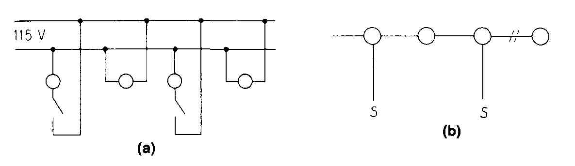
FIG. 1 Wiring diagrams of light-fixture outlets on a circuit: (a) true
wiring diagram; (b) simplified, or installation, diagram.
3. Wiring Symbols on a Simple Floor Plan
The architect usually shows the location of lights, convenience and special-purpose outlets, and the desired switching arrangements on a floor plan. For small, simple structures, the required symbols and wiring arrangements may be drawn on the same floor plan (Fig. 2) that shows all information necessary for the erection of the building. For larger or more complicated structures, complete wiring details will probably be drawn on separate floor plans, called electrical layouts or electrical plans. In either case, the simplified type of diagram, such as that shown in Fig. 1 b, will be used. This wiring layout will be drawn by an architect, engineer, or drafter who is familiar with the engineering and building-code requirements.
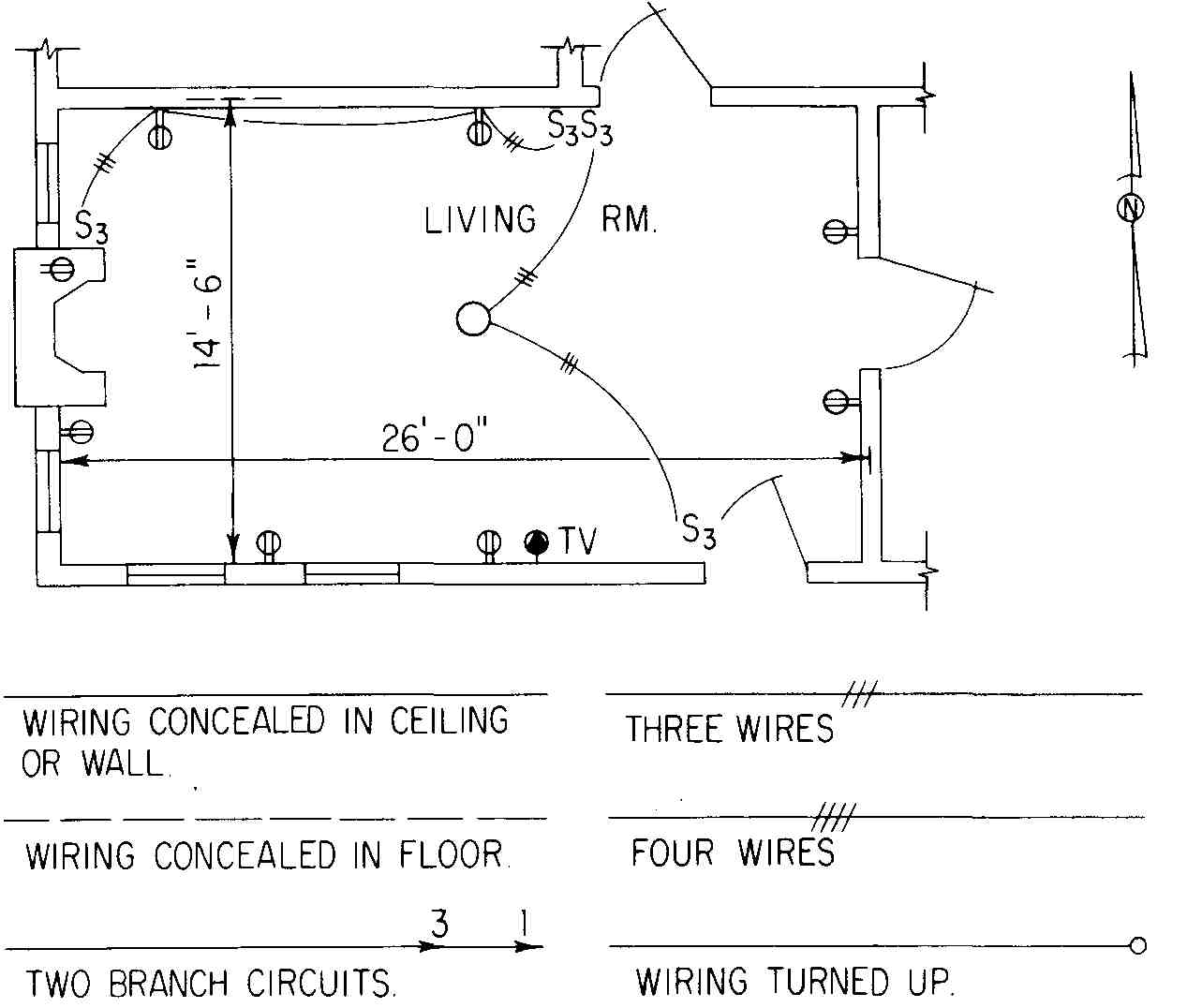
FIG. 2 Floor plan of a room with fixtures, outlets, and switches. Standard
wiring symbols are below.
The living-room plan (Fig. 2) shows two circuits: (1) the three-way switching arrangement for the ceiling outlet and (2) a similar arrangement for the two convenience outlets on the north wall. The outlet symbols, including the special-purpose outlet (indicated for TV antenna), are taken from ANS Y32.9. Also in accordance with the standard, the wire symbols for the switch- to-ceiling-light runs are drawn with a medium-weight solid line, indicating that the wires are to be concealed in the walls or ceiling above. Where no perpendicular dashes are shown across the wires, the conductors must have two wires. With the addition of a little more information about fixtures, the floor plan, of which the living-room plan in Fig. 2 is apart, will yield enough information for the satisfactory installation of the complete electrical system.
4. Separate Electrical Plans
A plan for the electrical system of a small business building appears in Fig. 3. This drawing was one of several, including plans and details for heating, air conditioning, and plumbing, which appeared on a single sheet.
This electrical plan shows the location of three separate distribution panel- boards and the proposed location of a future one. Panel C provides power service — mainly for the motors which run the mechanical equipment; panels A and B supply electricity for lighting and the other electrical needs of offices 102, 103, 104 and the vestibule. Each branch circuit is documented with an arrow pointing in the general direction of the panel and a designation such as A-2. This means, for example, that the nine fluorescent light fixtures in office 102 are on the same circuit, No. 2, which is fed at panel A. A separate telephone circuit, enclosed in conduit, is also shown.
A number of symbols that either do not appear in or differ from those shown in ANS Y32.9 are drawn in this electrical plan. The wall bracket outlets have the four prongs which are still widely used,’ but which are not shown in ANS Y32.9. A long-and-short-dashed line is used for circuit legs, regardless of whether the wires are run in the ceiling above, or the floor below, and the short-dash symbol is used for the switch leg. Confusion in the interpretation of these symbols is avoided by preparation of a legend.
5. Fixture Schedule and Legend
Figure 4 shows a legend and fixture schedule that accompanies the electrical plan in Fig. 3. Inclusion of such schedules and legends is the customary practice of architects and consulting engineers who prepare electrical layouts and details for the construction of buildings. The installation of the electrical system is facilitated by the inclusion of a letter designation at each fixture symbol and cross-referenced designations in an accompanying schedule. The exact form of the schedules has not been standardized. A “remarks” column has been omitted from the original schedule from which Fig. 4 was taken in order to conserve space.
One explanation for the continued popularity of the four prongs is that many persons feel that the plain circular symbol listed in ANS Y32.9 may be easily confused with other circular symbols which may appear on drawings.
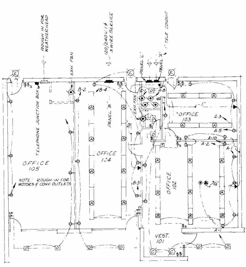
FIG. 3 Electrical plan for a small office building. (Brasher, Spencer & Goyette,
Architects-Engineers.)
A drawing should show intent, and in the most concise manner. Time, money, and argument will be saved if the proper information is placed in the legend. Too often, the person in the field does not see the written specifications, but does see the drawings and the legend. If the symbol for a floor convenience outlet appears, for example, the worker knows what the symbol means, but not which of the 50 available combinations is required, unless it is specifically stated. Now, if the legend reads “FLOOR CONVENIENCE OUTLET— Frank Adam FB-3,” the worker will know exactly what device to install.
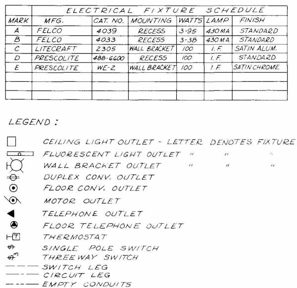
FIG. 4 Fixture schedule and legends for electrical plan of small office
building. (Brasher, Spencer & Goyette, Architects-Engineers.)
6. Example of Electrical Layout
Another electrical layout is shown in Fig. 5; this depicts the second floor of a three-story office building. This floor arrangement might be suitable for a drafting or design room. The wiring symbols conform reasonably to the American Standard code. Arrows indicate the circuit and number; half arrows indicate partial circuits.
Included with this electrical plan were a legend, lighting-fixture schedule, panel schedule, disconnect-switch schedule, telephone-circuit riser diagram, and electrical riser diagram. Of these, only the electrical riser diagram is shown in this section. Before it is discussed, a word about how energy is distributed throughout a structure seems to be advisable.
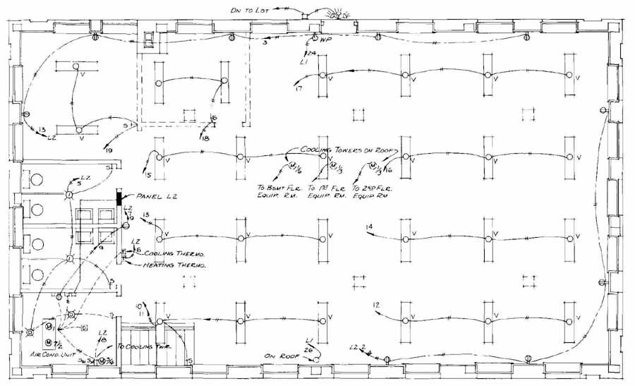
FIG. 5 Electrical layout of office building. (Tanner-Linscott & Associates,
Architects.)
As electric energy is brought into a building, it is usually first passed through a meter. From here it is brought into a main load center. In a small building or residence this load center consists of a fuse box or circuit breaker to which each branch circuit is connected. Through these branch circuits energy is fed to each outlet, lamp, or appliance. In a larger structure the main load center may be a large panelboard, or switchboard, with circuit breakers, disconnect switches, and other controlling devices. From this main load center, electric energy is fed through large conductors called feeders to branch load centers, often panelboards, or panels as they are sometimes called. From these panels energy is delivered through branch circuits to each outlet, fixture, appliance, or motor. Such factors as location of panelboards, voltage and copper losses, etc., determine the method used in connecting the branch and main load centers. Many different interconnecting layouts are used. More than one panelboard may be necessary on the same floor of a large building in order that excessively long runs of branch circuits be avoided. Sometimes separate panels are used for lighting circuits only, and others for motors and machines only. Often, panel- boards are used for combinations of types of circuit.
7. Electrical Riser Diagram
A riser diagram shows how electric energy is distributed through a building from the time it enters the building until it arrives at the branch load centers. It is drawn as an elevation and usually is not to scale. An electrical riser diagram for the building whose second-floor electrical plan is shown in Fig. 5 appears in Fig. 6. This diagram shows the electrical service passing through four meters, then through four disconnect switches. From switches S , S S the current goes to lighting panels L L and LB. From the latter two panelboards, energy goes to the lighting and convenience outlets in the ground floor and to mechanical equipment for the ground and first floors. Current travels from panelboard L through a subfeeder to L which supplies all the electrical service on the first floor, except for air-conditioning equipment. Panel L supplies electric energy to most of the circuits on the second floor. However, the electrical layout for this floor (see Fig. 5) indicates that outside lighting and mechanical equipment on the roof are connected to panelboards on lower floors.
The panelboard schedule which accompanies the riser diagram includes the following information about each panel:
1. The number of branch circuits to be served
2. Current-handling capability (amperage)
3. Name of manufacturer and catalogue number of panel
Similar information is given in the disconnect-switch schedule.
8. Electrical Drawings for Large Buildings
The next series of drawings illustrates the type of drawing required for large buildings. The standards are not as much help in showing such a complicated system; hence liberal use is made of orthographic projection, pictorial drawing, schematic diagrams, notes, and specifications.’ A very brief description of the general electrical layout of a large office building will be given by referring to the drawings, which in some instances have been simplified from the original for clarity.
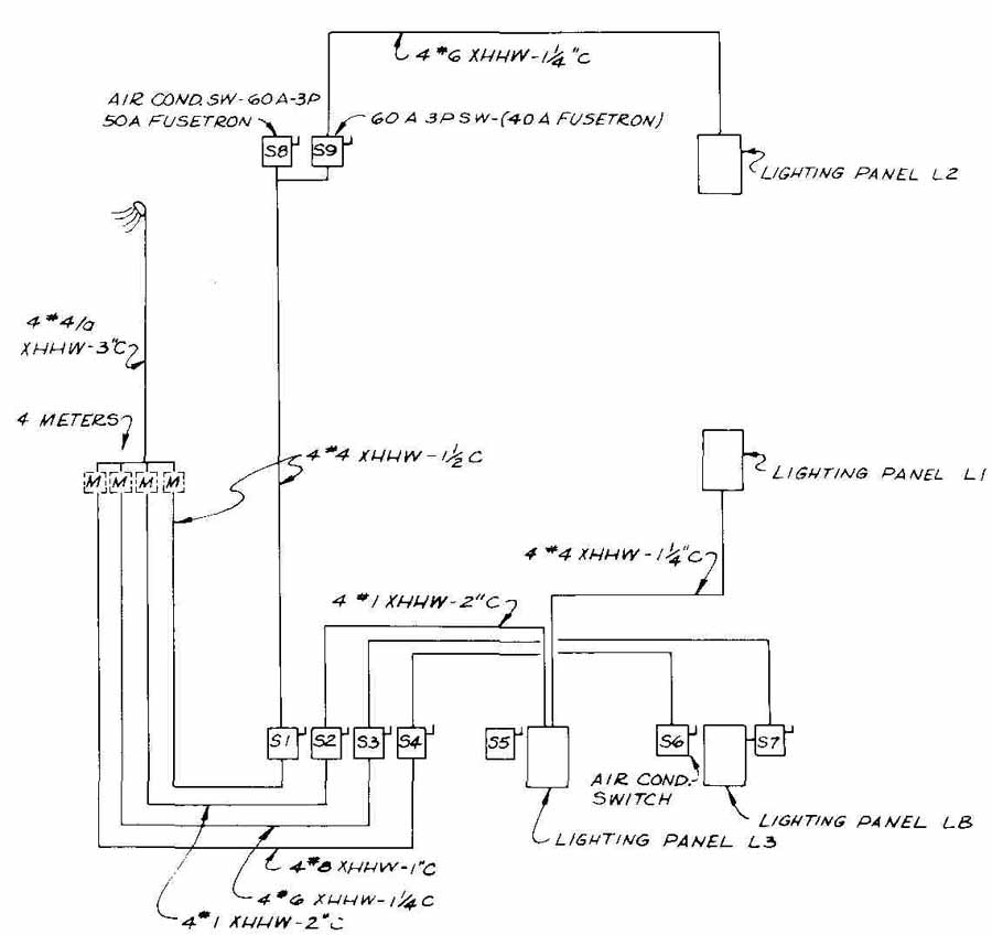
FIG. 6 Electrical riser diagram for three-floor office building. (J.
R. DeRigne & Associates, Consulting Engineers.)
The underground cables of the power and light company enter the building at the upper right, as shown in Fig. 7. They immediately are brought into a main service entrance, which is shown in some detail in Fig. 8. In the main service entrance are current and potential transformers (used for measuring current and potential), fuses, and switches, as shown in the one-line diagram. From the main service entrance the electrical service is fed to two 1000-kVA transformers (see Fig. 7), which step the voltage down to a four-phase state that provides 208-V three-phase service and 120-V single-phase service. From these transformers current is brought through 3000-A 4-4 (4-phase) busses to the main switchboard, shown in pictorial form in Fig. 9. From this switchgear, electric power is distributed by busses to various parts of the basement, as shown in Fig. 7. Actually the large copper or aluminum busbars themselves are not shown. Just the bus ducts are drawn — much the same as heating and air-conditioning ducts are drawn.
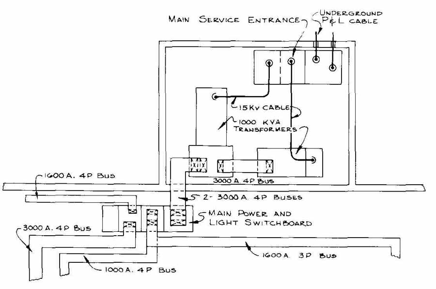
FIG. 7 Part of basement plan of large office building, showing details
of electrical service. (W. L. Cassell, Mechanical Engineer, and Tanner-Linscott & Associates,
Architects.)
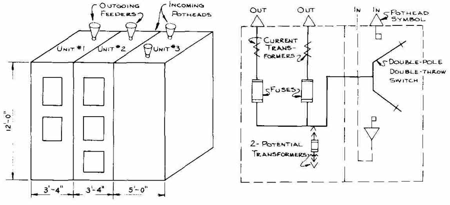
FIG. 8 Pictorial and one-line diagrams of main service entrance of large
office building.
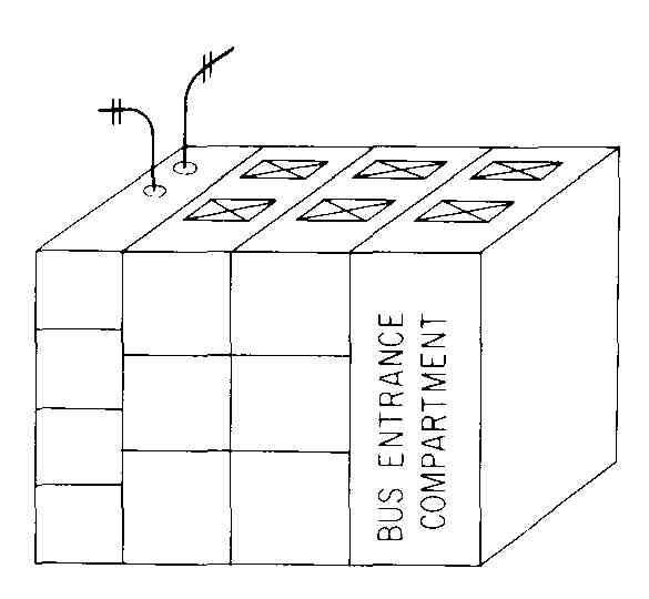
FIG.. 9 Pictorial drawing of main power and light switchboard of a large
office building.
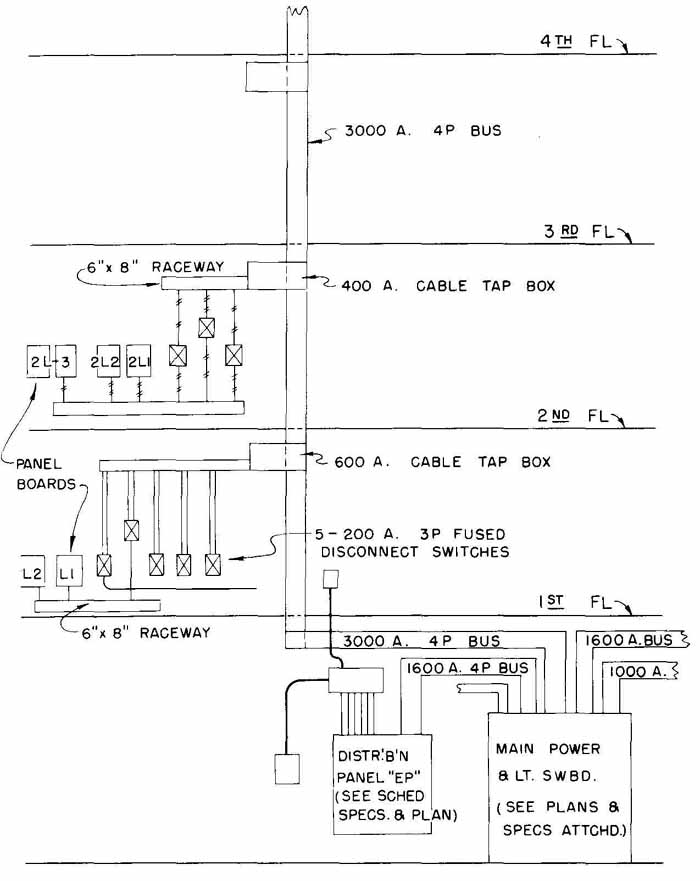
FIG. 10 Part of riser diagram for a large office building. (W. L. Cassell,
Mechanical Engineer.)
Service to upper floors is fed through the large 3000-A 4- bus—which is shown in both Figs. 7 and 10 (the riser diagram) — to branch load centers on each floor. At each branch load center are a cable tap box, disconnect switches, and panelboards. Here, use is made of metal rectangular raceways (also called “trays”), in which connecting cables are placed. From the panel- boards, service is distributed throughout the floors, as explained in the following two paragraphs.
Figure 11 shows a part of the electrical plan for the first floor. Shown in somewhat slight detail is the load center with its cable tap box and panels. Of special note is the underfloor duct system, shown by means of dotted lines. In these ducts, sometimes called raceways, are placed the wires for telephone service, 120-V single-phase electrical service, and 208-V three-phase service if desired. Outlets may be placed at any point along each of these ducts, and electrical service provided at each of these points. The ducts are covered with 2-1/2-in. of concrete, on which additional flooring material is often laid. The outlets are usually installed after the latter has been laid, but before the conductor cable has been pushed or drawn through the raceways. However, additional outlets may be emplaced along these ducts after the building has been completed and occupied, although new wiring may have to be poked through the ducts.
Figure 12 is a photograph of a raceway system being installed. Note that the raceways are often divided into more than one compartment. It is also possible to have a complete under-grid or cellular floor system. In this type of construction wires can be laid 12 in. apart all the way across the room in both directions. This provides a high degree of flexibility because a telephone, mini computer, or intercom connection can be placed anywhere in the room.
Details of various electrical hookups and appurtenances are often desirable or necessary. They may take several forms and have different amounts of information. Two detail drawings are shown in Fig. 13.
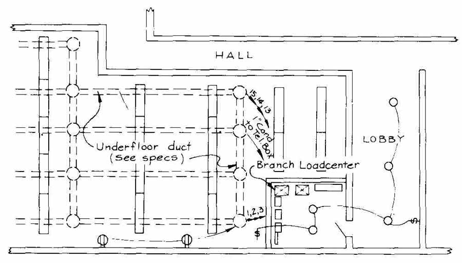
FIG. 11 Simplified electrical plan of first floor of a large office
building, showing underfloor ducts.
9. Coordination and Organization of Drawings
There are usually areas on every drawing which, from the electrical contractor’s viewpoint, should be made more comprehensive to help in preparing bids. Also the person doing the installing would benefit by having more information about correct or desired procedure, in many situations. However, it is possible to put too much information on the drawing — in trying to answer every question that may arise — and, as a result, confuse everybody from the contractor to the final inspector. Yet when special treatment is indicated, pertinent details should be supplied in order to present a logical and definite manner for the installation.
Many offices which prepare electrical and mechanical drawings for structures have improved their coordination with all crafts doing the work on a job. Such coordination (both before work starts and during the work) avoids conflicts between various mechanical items on the project. Last-minute changes in equipment by manufacturers cause some conflicts and cannot be fully predicted in advance. However, obvious conflicts can be avoided by proper coordination while the drawings are being made.
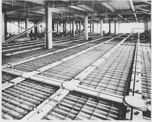
FIG. 12 Installation of an underfloor duct system. (Walker-Parkersburg.)
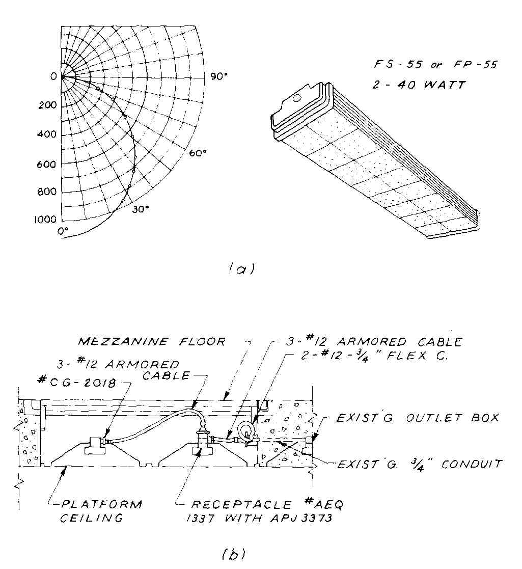
FIG. 13 Architectural details: (a) part of luminaire specification;
(b) cabling detail. (San Francisco Bay Area Rapid Transit District.)
If a consulting engineer is doing the wiring and mechanical design for an architect, their offices should also coordinate. Such things as space for raceways, ducts, and air-conditioning equipment must be provided.
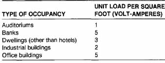
TABLE 1 General Lighting Loads by Occupancy
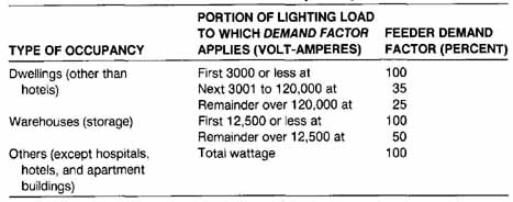
TABLE 2 Calculation of Feeder Loads by Occupancy
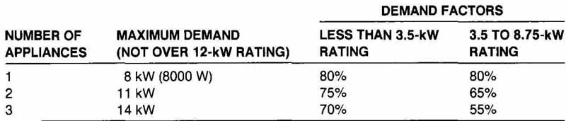
TABLE 3 Demand Loads for Household Electric Ranges, Ovens, and Counter-Mounted
Cooking Units over 1.75-kW Rating
10. Load Computation
With the information supplied in the National Electric Code (NEC), it is possible to compute the number of branch circuits and feeders required in many types of structure. Recently the NEC applied the term volt-amperes to general- usage areas. Volt-amperes is the apparent power that goes through a circuit. It is mathematically composed of watts (real power) and vars (reactive) (actually the square root of the sum of the squares). The ratio of watts divided by volt-amperes is called the power factor (pf). Therefore, if the pf equals 1 or 100 percent, the quantity of watts equals the quantity of volt-amperes. Since Tables 1 through 3 use either volt-amperes or watts at 100 percent power factor, they are equivalent. Let us assume that a residential dwelling has an area of 1490 sq ft, exclusive of basement, attic and garage, and a 1 2-kW kitchen range. Using Tables 1 through 3, we compute the general lighting load and other requirements as follows:
1. General lighting load
1490 sq ft at 3 VA/sq ft = 4470 VA (see Table 1)
2. Minimum number of branch circuits required
a. General lighting load (based on 115 V): 4470 ± 115 = 39.0 A. This can be handled by three 15-A two-wire circuits or two 20-A two-wire circuits. (The NEC recommends one circuit for each 500 sq ft.)
b. Small-appliance load: (Sec. 220-3 states that two or more 20-A branch circuits shall be installed to take care of small appliances in the kitchen, laundry, dining room, and breakfast room.)
3. Minimum-size feeders required:
If 115/230-V three-wire system feeders are used, the current load will be 12,565 ÷ 230, or 55 A. But, because the computed load exceeds 10 kVA, service conductors shall be 100 A [ 230—41 (b)(2)]. Feeder size can be selected from one of several tables in the NEC, which gives ratings for types of copper, aluminum, and copper-clad aluminum conductor. The feeders might be selected as No. 3 AWG copper conductor with rubber-type insulation, such as RHW or RUH, or with a thermoplastic-type insulation, such as THW or TFIWN; or the feeder might be selected as No. I AWG aluminum or copper- clad aluminum with the same types of insulation. As mentioned earlier, city building codes may have other requirements not specified in the National Code. Kansas City requires that all wiring be run in conduit for buildings (including houses) that happen to be in the Class A fire district. In other areas, conduits must be used in duplexes and multiple-residency buildings of two stories or more.
SUMMARY
Depicting electrical requirements for residential buildings, offices, and other structures requires a combination of graphical treatment, knowledge of building codes, and written specifications. For small structures, such as houses, it is usually sufficient to show electrical outlets, fixtures, and switches right on the house plans and to indicate what switching arrangements are required. In general, the rest of the circuiting arrangement is left to the constructor. But in larger buildings, it is necessary to depict all the circuit arrangements, including panelboard locations, in order to comply with safety requirements, to allow plenty of flexibility for future equipment and expansion, and to minimize expense of installing electrical work. National drawing standards ANS Y32.9 and Mu Std 15—3 (which are identical) are followed by most engineers who prepare electrical drawings. In depicting electrical requirements for buildings, it is necessary or desirable to make wiring plans, riser diagrams, and schedules for fixtures, raceways, conductors, etc. Symbol legends are sometimes used, especially if nonstandard symbols are used in drawings. Pictorial views and orthographic views of certain features and equipment are often quite helpful. Coordination by the person making the drawings with the architect, craftspeople, and equipment manufacturers is highly desirable because it will minimize conflicts and unnecessary installation expenses. Local building codes must be followed by the designer and constructor. When the local code does not cover a situation, the NEC must be consulted. If there is no local electrical code, the NEC should be used.
QUESTIONS
1. What authority, or authorities, shows the symbols to be used in making a residential floor plan that shows the electrical arrangement?
2. Why are riser diagrams usually not drawn to scale?
3. Why do we not use bus ducts in residential structures?
4. Sketch two different symbols which might be used to show a TV outlet.
5. What column headings would you use for a fixture schedule for a small building?
6. Why is it not customary to show two dashes across a circuit line for a two-wire conductor, when three dashes are customarily used to show a three- wire circuit?
7. Can you use the same graphical symbol for an electric-range outlet and for a dishwasher outlet?
8. Name three different schedules pertaining to the electrical system of a large building that might be found among the drawings for that building.
9. Name or describe two situations in which lines for the conductors themselves are not shown on drawings describing the electrical layout of a large building.
10. Does ANS Y32.2 cover the graphical portrayal of the electrical system of a residence?
11. Briefly describe three methods of providing underfloor electrical ser vice to an office building whereby electric current can be supplied at evenly spaced intervals throughout or across a room.
12. Where does a branch circuit begin? Name two kinds of branch circuit.
13. Where are overcurrent devices located?
14. What are two reasons for limiting the number of wires in a raceway?
15. What are the terminal points of a feeder (or feeder circuit)?
16. What is one difference between a switchboard and a panelboard?
17. What is the smallest rating a panelboard may have? Or to put it differently, what determines the minimum rating of a panelboard?
18. Under what conditions does the NEC say that raceways should not be installed?
19. What devices or systems can be used for grounding electrodes? (Name four.)
20. What is the minimum rating of a receptacle?
21. What can be done to avoid conflicts?
22. Why do some architects (or consulting engineers doing electrical de sign for architects) find it necessary or advisable to add legends to their drawings?
23. What sort of information would be contained in a legend for an electrical drawing?
PROBLEMS
Many of the problems are divided into two parts. Part a will be mainly a drawing requirement, and part b will involve computational requirements. In some cases, the instructor may require both parts; in other cases, only a orb. Computations do not need to be put on drawing paper. However, they should be neat, orderly, and correct.
1. The sketch of the floor plan of Fig. 14 shows all electrical outlets and fixtures and the relationships between the fixtures and switches of an apartment.
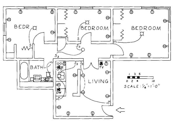
FIG. 14 (Prob. 1.) Plan of an apartment unit.
a. Make a mechanical drawing of this plan using currently approved symbols for wire runs, fixtures, and outlets. Wiring for duplex convenience outlets does not have to be shown except where they are controlled by a switch. Use 11 X 17 or 12 X 18 paper.
b. How many general 20-A and appliance 20-A branch circuits are required? If the range load is 8000 Wand 110/220 three-wire feeders are used, what will be the total current load for the first floor?
2. How many 15-A branch circuits will be required for the room shown in Fig. 2? How many 20-A branch circuits would be required for the office layout in Fig. 5? (The interior dimensions are 22 X 57 ft. Each fluorescent luminaire is 80 W.)
3. Figure 15 shows the floor plan of an apartment with all outlets, fixtures, and switches. Switches, for the most part, work overhead lights, but in the living room they operate two of the four outlets.
a. Make a drawing (mechanical or freehand) of this floor plan, adding doors and the necessary wiring. Show TV outlets in the living room and largest bedroom. Use standard symbols. Use 11 X 17 or 12 X 18 paper.
b. A feeder system of 115/230 V and three wires is used and the kitchen range is rated at 11 kW. How many 15-A branch circuits will be required for the apartment? What will be the total current load?
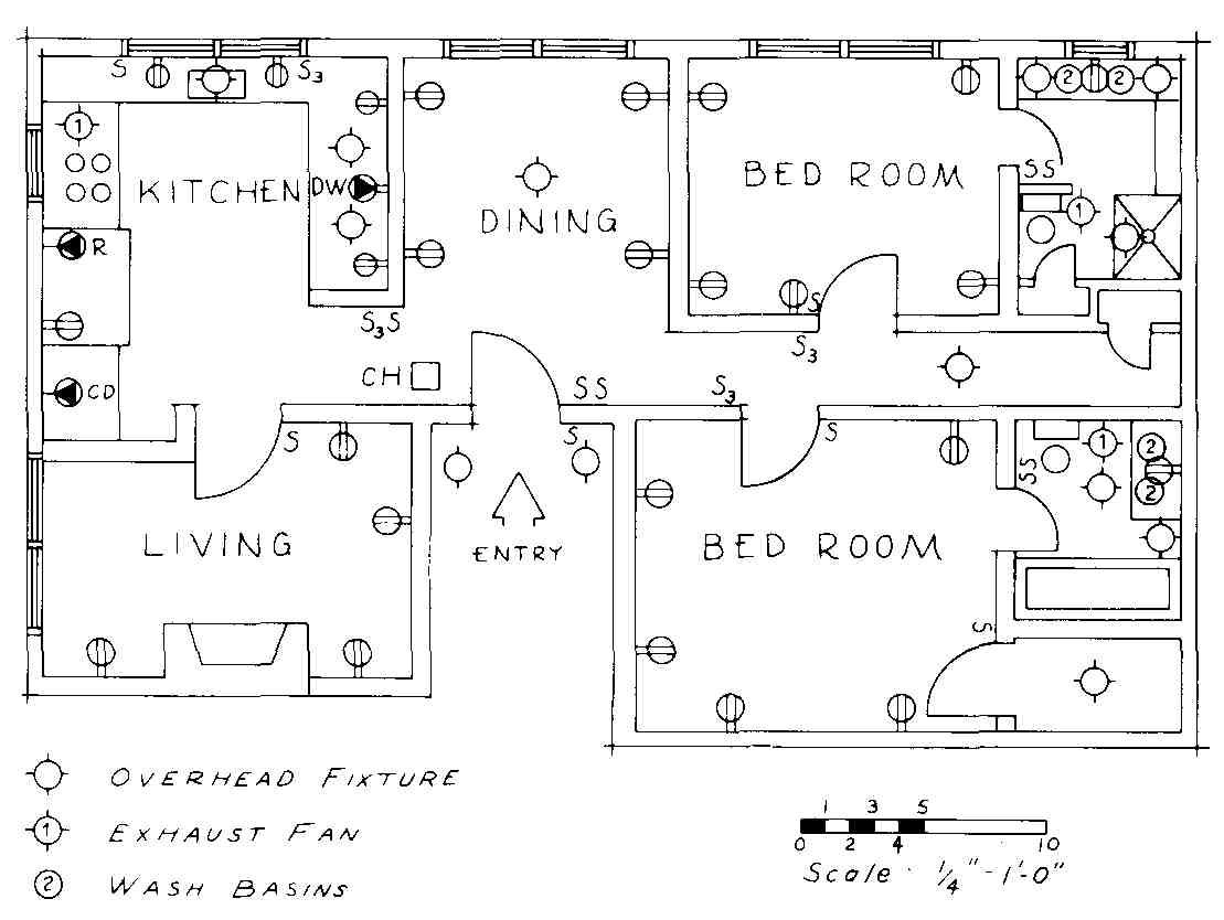
FIG. 15 (Prob. 3.) Floor plan of luxury apartment.
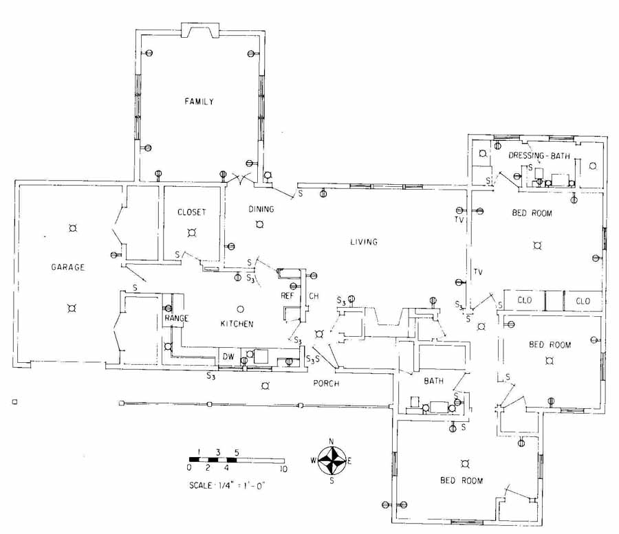
FIG. 16 (Prob. 4.) Floor plan of three-bedroom residence.
4. Figure 16 is the floor plan of a one-story residence.
a. Draw this plan to a scale of 1/2i in. = 1 ft 0 in. Show all switching arrangements as you think they ought to be. At least two duplex outlets in the living room are to be controlled by switches at the north entry. Use standard symbols throughout the drawing.
b. The kitchen range has an 11 -kW rating, and 220-V three-wire feeders are used. How many branch circuits (general and appliance) will be required? (What will the difference be if central air conditioning is installed?) What will be the total current load to be used for computing the size of the feeders?
5. Figure 17 is the first floor plan of a two-story house with all outlets and fixtures shown.
a. Draw this plan to a scale of in. = 1 ft 0 in., and show all switching arrangements as you believe they should be made. Use correct symbols as given in the Appendix. Optional: show circuits for the convenience out lets. Use 11 X 17 paper.
b. Assume the house has three bedrooms and a hall upstairs. For an 8-kW kitchen range and the other equipment shown, how many and what kind of branch circuits would be required for the house? What is the total energy requirement?
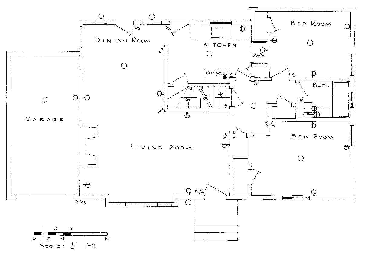
FIG. 17 (Prob. 5.) Floor plan of first story of residence.
6. The lighting fixtures for a drafting-design room are shown in Fig. 18. If the fluorescent lights are rated at 80 W each, estimate the number of branch circuits needed. An electrical outlet should be put near each desk. Four desks are placed under each row of luminaires, making a total of 24 drafting desks. Lights will be turned on and off at panel L Other circuits go to panel L on another floor. Make a scale drawing of this room, and show all circuits. Use 11 x 17 or 12 X 18 paper.
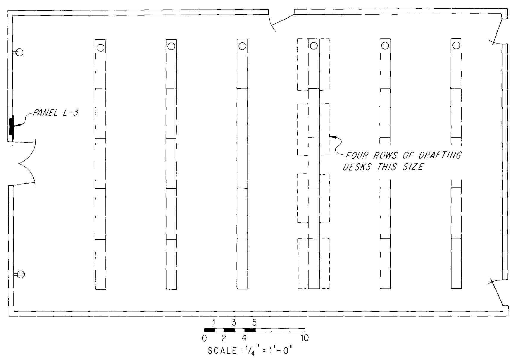
FIG. 18 (Probs. 6 through 8.) Floor plan of drafting-design room.
7. Under each luminaire shown in Fig. 18 will be placed a designer’s desk. It is desired to have provisions for electric erasers, telephones, and electric calculators at each desk. Make a detailed drawing that includes a system of underfloor raceways which will provide this electrical service to all desks. Assume that telephone conductors and 115-a conductors can be placed together in a raceway. Use 11 X 17 or 12 x 18 paper.
8. Because the telephone company objected to having telephone lines in the same duct with other conductors, it was decided to install a cellular-type, underfloor wiring system for the drafting room in Fig. 18. Draw the floor plan to scale, showing a cellular system that will supply 115-v ac energy to outlets at each desk, and separate cellular ducts for intercom and telephone service to each desk. Overhead lighting may be included in the drawing. Use 11 x 17 or 12 X 18 paper.
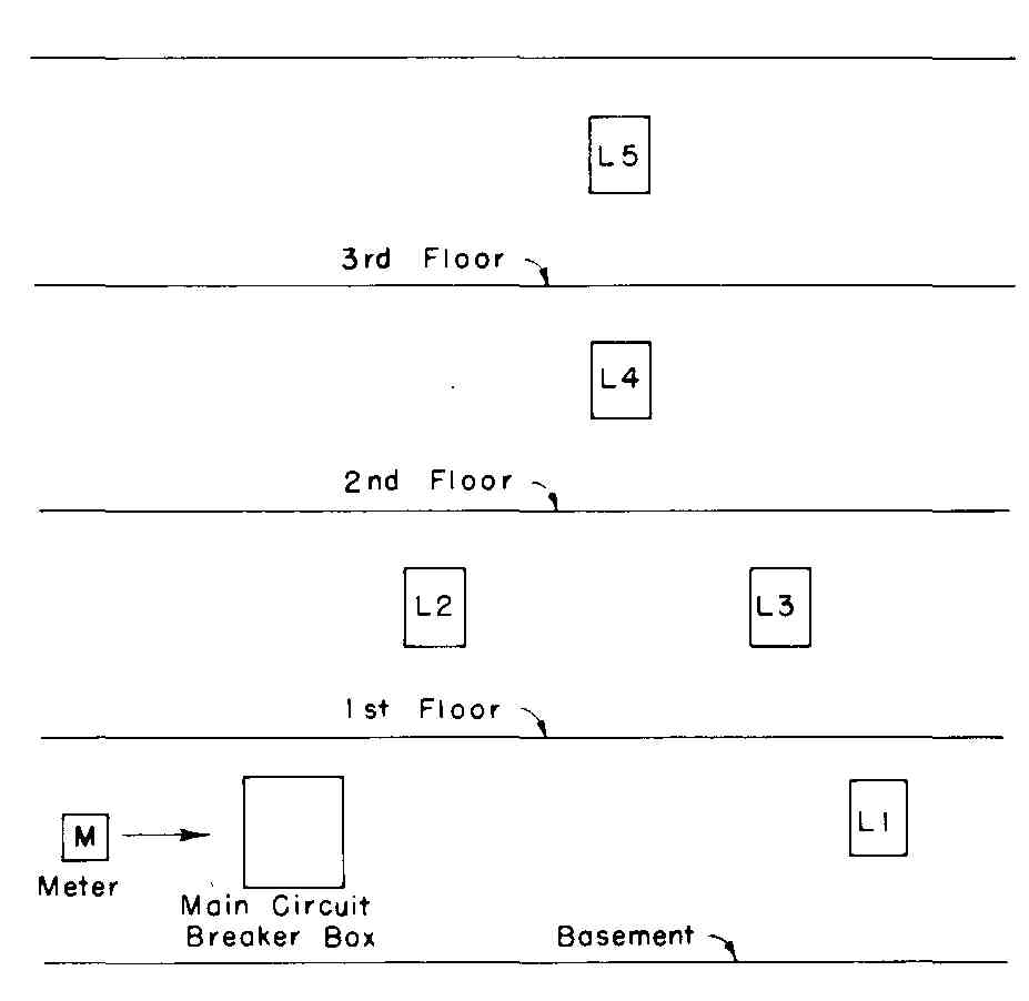
FIG. 19 (Prob. 9.) Section elevation of three-story office building
with electrical distribution equipment.
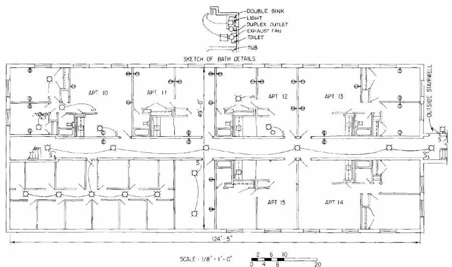
FIG. 20 (Prob. 10.) Electrical and heating plan of ground-floor apartments.
9. Figure 19 shows a section of a three-story building with a basement. Draw a riser diagram for this building as you believe it would be designed. Figure 6 will give you an idea of what conductor sizes to use. Use XHHW insulated wire; XHHW insulation is heat- and moisture-resistant and made of a synthetic, cross-linked polyethylene. The current-carrying capabilities of XHHW insulated copper conductors in damp locations are as follows:
CONDUCTOR SIZE (AWG) |
AMPACITY |
14 12 10 8 6 4 3 2 1 |
15 20 30 45 65 85 100 115 130 |
10. The incomplete heating and electrical plan of one floor of an apartment building is shown in Fig. 20. Overall dimensions are also shown. Apartments 10, 13, and 14 are identical except that they are reversed. The same is true for apartments 11, 12, and 15.
a. Make a complete scale drawing of this plan, showing all circuiting and switching arrangements for all the rooms and the hall. Appliance loads are 8 kW for ranges, 2 kW for dishwashers, and 4.2 kW for washer-driers. These appliances will be located in the kitchen of each apartment. Their exact locations and outlets are not shown. (Use 12 X 18 paper for a fin, to 1-ft 0-in, scale.)
b. If a copy of the NEC is available, compute the minimum number of branch circuits and the minimum size subfeeder for each apartment. Compute, also, the main feeder for this floor and the rating of the panel, if one panel is used.
11. Letter a fixture schedule to accompany an electrical plan. Such a fixture schedule might include the information shown in Prob. 1-7, Section 1.