AMAZON multi-meters discounts AMAZON oscilloscope discounts
Before a machine or system using electronic parts is made or built, instructions must be given to the persons who will be involved in the fabrication or assembly. Such persons are likely to be engineers, machinists, electrical installers, assembly workers, time-and-motion engineers, computer and numerical control (N/C) programmers, printed-circuit (PC) board designers, robotics technicians, and electrical and electronic drafters and detailers. Some of these people may be giving the instructions, some may be on the receiving end of the instructions, and some may be doing a little of both. Drawings convey these instructions very well, although they sometimes must be accompanied by other information. There are several different kinds of drawings used for this purpose. Correct or recommended practice for most of these drawings is set down in certain ANSI, IEEE, and Military Standards. Some of the more relevant standards are listed below:
ANSI Y14 “Drafting Manual,” which includes:
14.1 “Drawing Size and Format”
14.2 “Line Conventions, Sections and Lettering”
14.3 “Multi and Sectional Drawing Views”
14.4 “Dimensioning and Tolerancing for Engineering Drawings”
14.6 “Screw Threads”
14.15 “Electrical and Electronics Diagrams”
Mil Std 242 “Electronic Equipment Parts (Selected Standards)”
Mil Std 196 “Joint Electronics Type Designation System”
Mil Std 429 “Printed Wiring and Printed Circuits Terms and Designation”
Mil Std 681 “Identification, Coding and Application of Hook Up and Lead Wire”
Company standards, if any, that may be more specific or restrictive than ANSI, IEEE, or Military Standards
In this Section we will discuss the following types of drawings that are commonly used for production:
- Wiring or connection diagrams
- Cabling diagrams
- Harness diagrams
- Sheet-metal layouts
- Assembly drawings
Connection Drawings
1 Connection, or Wiring, Diagrams
In order to connect various parts (motors, resistors, capacitors, connectors, displays, and circuit boards) it has been the custom to use or follow a connection diagram. The older name for this type of drawing is wiring diagram, and, because it is so widely used, we shall use these two terms interchangeably.
In a manufacturing company these drawings are used by the time-and- motion, quality-control, and estimating sections, as well as by individual workers. Wiring diagrams are also used in the maintenance area by persons doing checking, troubleshooting, and modification. Sometimes they are used with schematic diagrams (explained in Section 7) to provide additional information.
In low-volume production, a connection diagram may be used at first and then put away after the worker has memorized the steps and connections. In some instances companies with active methods sections are able to produce without such a drawing.
In high-volume production (ICs, PC boards, consumer products, etc.) the connection diagram alone is not used for connecting parts, but rather is just a step in the design-manufacture process.
2. Types of Connection Diagram
These diagrams may be classified according to their general layout as follows:
1. Point-to-point
2. Highway, or trunkline
3. Baseline, or airline
4. Straight-line
There are also other ways of labeling wiring diagrams, as the reader will discover. Such titles might include cabling, harness, and interconnection diagrams.
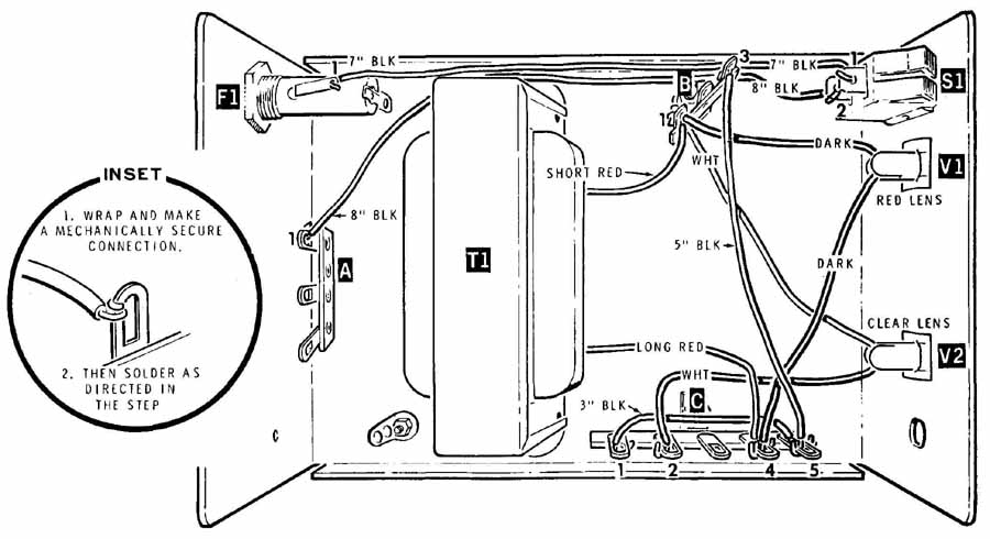
FIG. 1 A pictorial point-to-point wiring diagram.
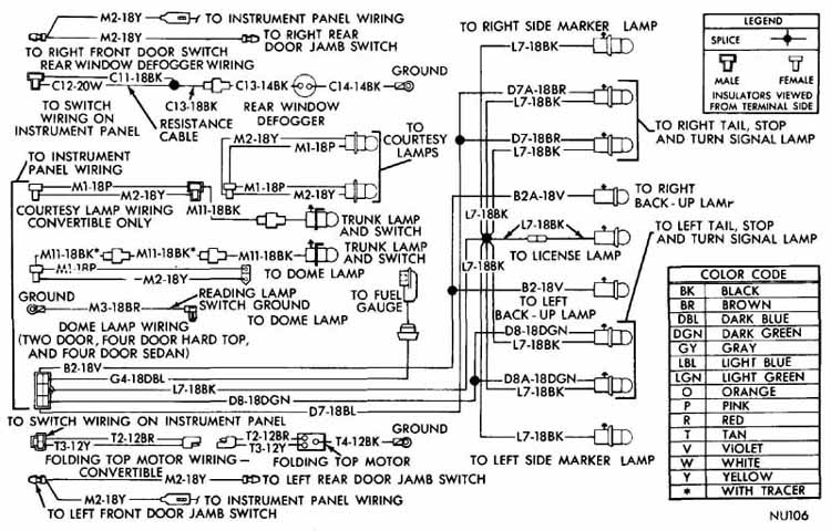
FIG. 2 Pictorial wiring diagram for an automobile. (Chrysler.)
3 Point-to-Point Diagrams
This is the oldest type of wiring drawing. FIG. 1 shows a pictorial form of the diagram in which each part and terminal are drawn about as they appear to the viewer. This type of drawing has met with great success in the do-it kit industry and other places.
FIG. 2 is another type of pictorial point-to-point diagram, but it is not as close to what the actual object looks like as is the first drawing. Many of the symbols are pictorial, but their physical relationship to each other is not accurate. Furthermore, the lines representing the wires (conductors) are drawn either horizontally or vertically, not as they actually are placed in the chassis or frame of the automobile. A distinctive feature of this drawing is the color code and identification system required when there are as many wires as are presently utilized in motor vehicles. The wire in the upper right corner, for example, is L7-18BK. This means that this is conductor L7, which is of size 18 wire and is black in color.
In the two drawings discussed so far, the component parts have been drawn pictorially. Inmost wiring diagrams, these parts are shown by means of symbols or by simple geometrical figures such as squares, rectangles, and circles. This will be the case with the connection diagrams that follow, including the aircraft wiring diagram in FIG. 3.
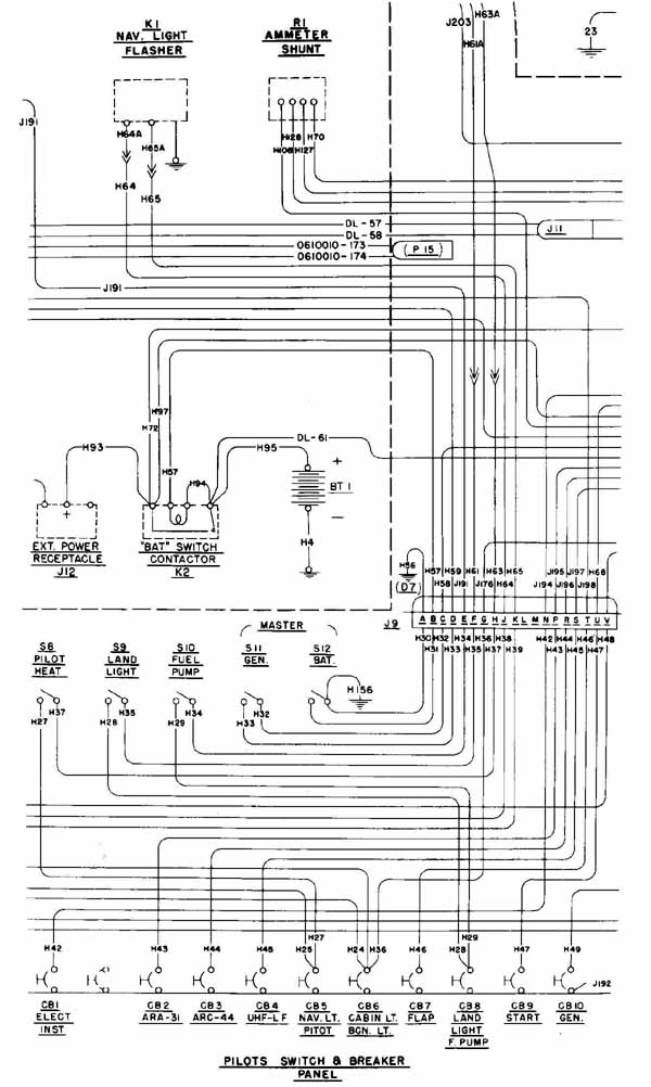
FIG. 3 Connection (wiring) diagram for a small aircraft. (Cessna.)
FIG. 3 shows only a small part of the original drawing, but it contains enough details to give a fair picture of what such a drawing looks like. Note the switch symbols* S S etc., the battery symbol, BT and the circuit-breaker symbols, CB CB etc. Note, also, the uniform spacing of wire conductors, drawn about - in. apart, with their rounded “corners.” Actually, most of the wires are routed in bundles (harnesses), and the physical routing of wires probably does not bear close resemblance to the way they are drawn here. Item .19 below center and right, is a female receptacle into which male connector D is plugged. The letters represent the pins in the connector. Readers will have a difficult time tracing the paths of many of the wires in this drawing because only part of the drawing is here. They can trace line H from switch S to CB and line H from S to J however. In Figs. 2 and 3, medium-weight lines have been used to represent wires. This is common practice, although some manufacturers draw all or certain conductors more heavily.
4 Interconnection (external- wiring) Diagrams
FIG. 4 is another example of a point-to-point wiring diagram. It consists of several PC boards and motors of a rob t and individual wires or cables that go from terminals in one board or motor to terminals in another board. The large rectangle called I/O / CPU has the microprocessor and related circuitry as well as input ports on the left side and output ports on the right. Each port has one or more pin connectors, labeled F F and so on. Internal connections on the boards are not shown, only the external connections. Therefore this type of diagram is called an interconnection (or interconnect) diagram.
* In many diagrams in this guide (and elsewhere) letters and numbers (subscripts) are made the same height.
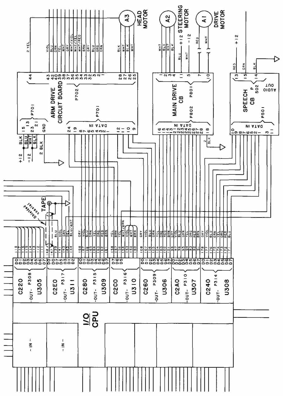
FIG. 4 Part of the interconnection diagram
====
TABLE 1 Component Number
Assignments by Location*
0—099 Parts found on robot chassis
101—199 Parts found on sonar transmit board
201 —299 Parts found on power supply board
301 —399 Parts found on I/O board
401 —499 Parts found on CPU board
501—599 Parts found on speech board
601 —699 Parts found on sense board
701 —799 Parts found on arm drive board
801 —899 Parts found on main drive board
901—999 Parts found on remote controller
* Last five lines omitted. This list was printed in the lower right-hand corner of the block-interconnect diagram shown in FIG. 4. (Reprinted by permission of the Heath Company.)
===
As in the previous example, all conductor paths are drawn horizontally or vertically, but with sharp corners. Each path has a number and color and is assigned to a pin location on the circuit board. A three-letter color abbreviation system is used, with BLU for blue, GRN for green, and ORG for orange. A shielded coaxial conductor is shown as No. 148 leading from C2EO to the tape-out jack and is attached to a common chassis connection. FIG. 4 is not quite a pure point-to-point diagram because the wires leading from I/O port C feed into a highway. This aspect is discussed in Sec. 6. Only part of the diagram has been shown, and some lettering has been deleted to facilitate reading of the drawing.
Another body of information appears on the same sheet as the interconnect diagram in FIG. 4. This is the number assignment for components (parts) mounted on the various PCBs of the robot. Table 1 shows most of this information. We have explained, with examples in Section 3, how components are identified by number and sometimes by function.
5 An Example for Types of Wiring Diagram
A stereo system is shown in FIG. 5 with the wires connecting the various components. A typical point-to-point diagram of this system is shown in standard form below the pictorial view. Each part has been shown as either a rectangle or a circle, which is generally standard practice. And each part has been assigned a number, pretty much in an arbitrary manner, although as the reader will notice, we did start with the item (record changer) that was at the top and go downward, 1, 2, 3, etc. The rectangles and circles representing the major components need not be arranged to correspond to the actual location of these items with regard to each other, although an attempt to do so will make the diagrams easier to draw and read. The large boldface numbers representing each item should follow some sequence, left to right or up and down, if possible. As was the case in Figs. 3 and 4, neat arrangements of parallel lines that include equal spacing where several lines are in a particular area is obtained in the point-to-point diagram. The lettering code is different from the preceding example in that one or two letters are used. One-letter designations are adequate for such colors as red, white, yellow, and orange, but two letters are necessary for certain others such as black (BK), blue (BL), brown (BR), green (GN), gray (GY), and slate (SL). The wires joining terminals 2 and 3 of the speakers are called Straps or pigtail leads and do not require color designations.
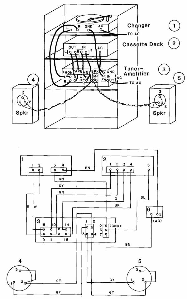
FIG. 5 Pictorial diagram and point-to-point diagram for stereo equipment
wiring.
6 Highway, or Trunkline, Type of Wiring Diagram
Practically any electrical assembly or system can be shown wired or connected graphically by the point-to-point method. But the same assembly or system can also be connected graphically by other methods. Sometimes the point-to-point diagram gives the clearest picture and fastest reading, yet, at other times, one of the other methods might give the best picture and provide easier and quicker reading. One of these other methods is the highway type of connection diagram. (We mentioned that a highway was shown in the interconnection diagram in FIG. 4.) This type differs from the point-to-point style in that conductors (conductor paths might be better) are merged into long lines called highways (or trunklines) instead of being drawn as separate, complete lines from terminal to terminal. The short lines leading from the terminals to the highways are called feed, or feeder, lines, and must have some sort of identification near the highway so that the conductor path can be followed by the reader.
One or more highways may be shown, depending on the wire routing necessitated by the physical (or graphical) arrangement of components. These trunklines do not have to conform to actual bundles or harnesses, if such are used. FIG. 6 shows the connection of the stereo equipment of the example ( FIG. 5) in the form of a highway diagram. The components have been drawn and numbered exactly as they were in FIG. 5. The highways were located about 1.25 in. (32 mm) from the rectangles; thus the feeder lines from the terminals were comparatively short, yet long enough for some identification to be placed close by. We were able to prevent any highway from crossing another and feeders from crossing each other or a highway. (This may not be possible in certain diagrams, but crossings should be kept to a minimum.)
Each conductor (feeder) has identification in the form of ( 1) component or part destination, (2) terminal at the component destination, and (3) wire color. Thus the feeder leading from terminal 1 of component 1 has the following identification: 3/8-W, which means that it goes to part 3, terminal number 8, and the wire is white. Going to component 3, terminal 8, we find the other end of this connector, which has the “reverse” designation, 1/1 -W. The highway is usually drawn the same weight as the feeders, but it may be drawn heavier.
Where the feeder joins the highway, an arc or 45-degree line is drawn, and this line or arc should be in the direction the wire is headed.
A different method of identifying circuit paths is in wide use. This ANSI- recommended method suggests that each feed line have this designation near the point where it joins the trunkline: (1) component destination, (2) terminal or component part, (3) wire size or type (if necessary), and (4) wire color. In FIG. 7,the top feeder line at terminal board 12 carries the following identification: TB14/4-B2. Broken down, this would be: TB14—destination; 4— terminal at destination; B—size of wire (say, No. 22 hookup wire by a prearranged code); and 2—color (red, by Mil Std 122 color code shown on the drawing and in Appendix C). Going to TB14 and terminal 4, we find the other end of this connector, and here it has the reverse identification, TB 12/1 -B2.
The choice of location and number of highways may depend on several factors. Separate highways for different cable groupings may be desirable. If a group of wires needs to be segregated or shielded, a separate highway for that group may be desirable. Such a highway might be drawn close to, and parallel to, another highway. Occasionally situations may arise where certain wires, called critical wires, should be drawn from point to point and not merged into a highway. Special identification for these wires may be necessary.
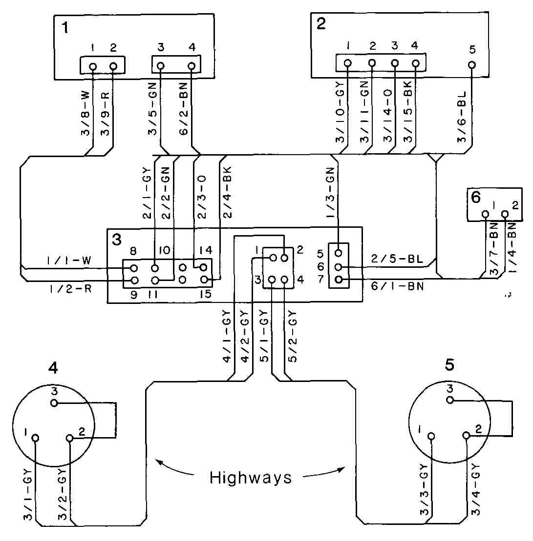
FIG. 6 The wiring of the equipment shown in FIG. 5 drawn as a highway
diagram.
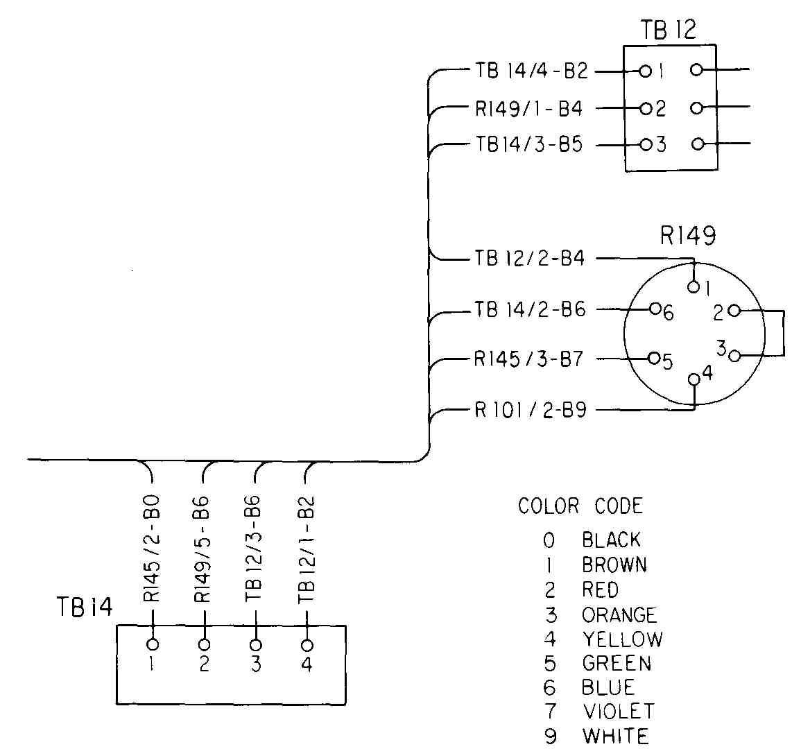
FIG. 7 Part of a highway diagram using the ANSI identification system.
The 45 degree lines where the feeder joins the highway are about 0.20 in. (4 mm) long, and the arcs, if used, should have radii that are about 0.20 in. (4 mm).
The highway type of connection diagram is particularly suited for showing the wiring of large panels where there are many terminals and conductors. FIG. 7 is part of a panel-wiring diagram. A panel-wiring diagram generally shows the back, or wiring, side of the panel. Terminal strips, switches, breakers, etc., are usually shown in exact or approximate position with regard to each other. Sometimes the panel is drawn as a scale drawing showing all terminals, lights, lettering, and switches, and the wiring is shown diagrammatically usually on the same sheet.
7 Airline, or Baseline, Diagrams
These wiring drawings, with a rather misleading name, are similar in some ways to highway diagrams. The airline, or baseline, as it is sometimes called, is an imaginary, usually horizontal or vertical, line conveniently located so that short feed lines may be drawn from component terminals to it.
The stereo system used previously has been drawn in this manner in FIG. 8. It has six horizontal baselines and one vertical one. (In many such diagrams, all baselines are horizontal.) In our example these lines have been drawn heavier than the others, but in many such diagrams the baselines and feeder lines are of the same weight. The feed lines are drawn at right angles to the baseline but without the curves or 45 degree lines that are in highway diagrams. Good identification of conductors is a necessity. In FIG. 8, the same identification system is used as in FIG. 6. The major difference between airlines and high ways is that a highway must go from one component to the destination component, sometimes making several bends and turns to get there, but an airline may stop at any convenient place and another airline may be drawn near the destination component. In airline drawings having many component parts there are many airlines spotted at different places close to groups of parts. In such cases, a feed line may enter one airline and come off another airline. This makes for slower reading and tracing of conductor paths, but for systems or packages containing many wires and terminals, the airline type of diagram may be less cluttered and confusing than point-to-point and highway drawings are.
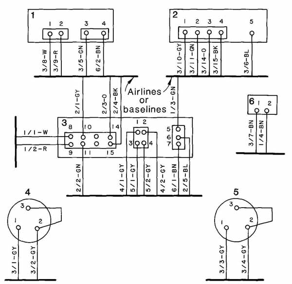
FIG. 8 Wiring of the equipment shown in FIG. 5 drawn as a baseline,
or airline diagram.
Sometimes, so many components are present in a large system that if they were shown as one column or strip, the airline diagram would be too long and narrow for practical purposes. To avoid this, the diagram may have to be laid out in several columns side by side.
8 Straight-Line and Hybrid Diagrams
Another type of wiring or interconnection diagram is the straight-line type that is shown in FIG. 9. Instead of drawing the components or terminals as rectangles, circles, etc., each component number is listed at the top with a vertical line directly underneath. Conductors that go to each component are shown with a connection dot and the terminal number close to the dot. Wire colors are placed above, often near the center of the “span.”
Component numbers usually start with the lowest at the left and increase, with the highest at the right.
We have started with the wires or conductors from part 1 (refer to the lower part of FIG. 5) that go to part 3 since there are no connections between 1 and 2. After those three wires are placed on the diagram, and the wire from terminal 4 to part 6 is drawn, we start with the connectors that are on part 2. This type of diagram has similarities with the wiring list shown in the next section. Although not as explicit as the previously explained diagrams, such a diagram is very helpful to estimators and installers of very large and complex systems.
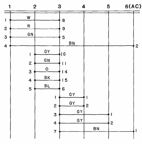
FIG. 9 The equipment of the preceding examples drawn in the form of
a straight-line diagram.

FIG. 10 Connection diagram (a) and elementary diagram (b) of a motor
starter.
Frequently, it is desirable to show the wiring diagram and the schematic (elementary) diagrams on the same drawing. FIG. 10 shows these two diagrams for a motor controller. In this panel-wiring drawing, two different line widths are used for conductors. Narrow lines, say, - in., are used for the control, or pilot, section of the circuit; and wide lines, say, 3l in., represent the line-voltage part.
For very complex installations, it may be necessary to compile wiring lists or to-and-from diagrams in addition to, or in place of, connection diagrams. A typical heading for such a list might be:
Additional information, such as routing (conduits, ducts, etc.), function, and military type number, may be shown.
9 Line Spacing and Arrangement
The reader may or may not have noticed the neat, uniform line spacing in some of the examples — particularly the point-to-point diagrams. This spacing and layout were not achieved accidentally, but rather by careful planning and good use of drafting aids. Two especially helpful aids are (1) the preliminary freehand sketch (or sketches) and (2) a commercially produced or office-made undergrid.
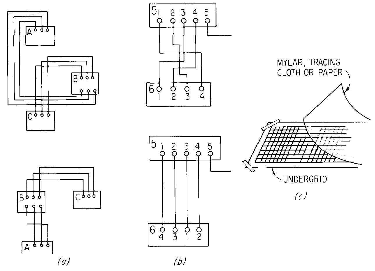
FIG. 11 Layout of wiring diagrams: (a) experimenting with location
of components; (b) changing terminal locations; (c) using preprinted
undergrid.
When making the original sketch, it is advisable to consider laying out the components so that the simplest, neatest wiring diagram will result. This may include changing the location of the components with regard to each other (if such juggling is permitted) and changing the order of the terminals. Rather elementary graphic examples are shown in FIG. 11. The shorter and more direct the lines are, the quicker and easier it is for the reader to trace the paths. Keeping the crossings to a minimum also facilitates reading.
Spacing of parallel lines is most often at 1/4 in. This permits use of a prepared under-sheet having 1/4-in. grids, which, if a transparent drawing medium is used, greatly facilitates the making of the final drawing. For various reasons (lettering requirements, reduction of drawing) other spacings may be required.
10 Wiring Harness or Cabling Drawing
A large portion of the expense in producing complex electronics assemblies can be laid to the wiring. The wiring operation can be optimized (made simpler and cheaper) by study of the chassis and connection drawings, followed by the drawing of a harness diagram. This is generally done in a series of steps:
1. Study of the mechanical assembly, noting the general path which the harness should take and any obstacles which might cause difficulty.
2. Making a drawing of the outline of the harness. This can best be done if a suitable full-scale chassis or assembly drawing exists. A sheet of tracing paper or other translucent drawing medium is then placed over the drawing and the harness outline done on the top sheet.
3. Completion of the harness (sometimes called local-cabling) diagram itself, using the assembly drawing and the wiring drawing for the assembly. This may include “breakout” points where individual wires (or several wires) break out of (or enter) the harness and where nails or pegs will be driven into a board or jig on which the cabling will be assembled.
4. Proper identification of each wire on:
a. The drawing itself.
b. A table or listing of wires by color, etc.
FIG. 12 shows a typical local cabling, both by itself and as it later appears connected to the assembly. There is additional cabling and wiring on the same assembly.
FIG. 13 shows how such a diagram may be begun, and FIG. 14 shows the final full-scale drawing of the harness with breakout points and lines showing where the wires are stripped. For example, the wires in the upper left corner extend beyond the line marked 104, 5 but are stripped back to this line, and the bare wire is cut so that in. remains beyond the line. The approximate thickness of the cabling is shown and is based on the number (and thickness) of wires that are in the harness at these places. If 26 wires are in the center part, the approximate thickness there would be about X (thickness of insulated No. 22 wire), or about - in. plus, which is only slightly less than what the finished harness measures at this point.
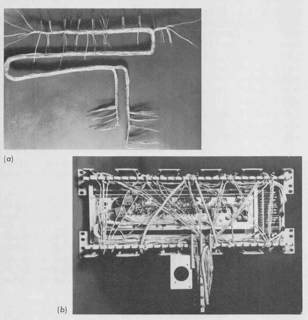
FIG. 12 Photograph of a local cabling harness: (a) harness by itself;
(b) harness attached to chassis. (AT&T Technologies, Inc.)
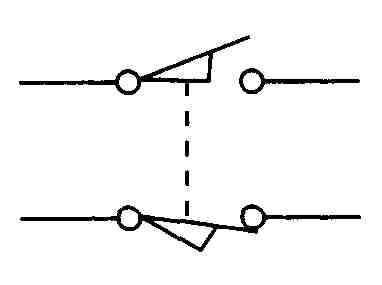
FIG. 13 Fitting a harness drawing into the spaces available in a chassis.
Table 2 shows the tabular form of wire identification and routing. It is often placed on the same sheet as the harness drawing. This system uses a sort of “station” method whereby leads numbered in the 100s are at one area of the harness and those numbered in the 300s and 400s are at other areas, or “stations,” along the harness. Other numbering systems are sometimes used. FIG. 14 is one of a set of drawings made for the assembly of the electrical equipment. Other drawings might include a schematic diagram and connection diagrams.
Another harness drawing is shown in FIG. 15. This is a pictorial view of a harness and flat cable on a hinged chassis or panel with the door shown in its open position. Breakout points are prominently identified by number as BO #1, BO #2, etc. Wires are identified by color at critical places. In the case of the flat cable, the edge with the brown wire is identified at both ends. Pin connectors and connector shells are shown in their exact locations and identified.
More explicit information on connections may be provided as in FIG. 16. These show the connections for each wire at the right in FIG. 16a and similar treatment at the left end. (An insert not shown here provides more information about how the capacitors and the individual plug-in connectors are attached to the wires.) The connections for the flat cable in FIG. 16b are shown at the right end, and individual plug-in connectors are illustrated at the left end.
FIG. 14 A harness drawing intended for installation purposes.
Similar drawings are sometimes accompanied by a parts list which might identify each end connector by type and manufacturer part number, type of sleeving, length and color of each wire, solder specification number, etc. The many different types of end connectors and terminals make it almost impossible to cover this subject in a book.
FIG. 15 A pictorial drawing that includes a harness and a ribbon,
or flat-cable, connector.
TABLE 2 Harness-Wire Routing
Note: This tabulation is part of the drawing shown in FIG. 14.
Construction and Assembly Drawings