AMAZON multi-meters discounts AMAZON oscilloscope discounts
[cont. from part 1]
11. Sheet-Metal Layouts
In order that the frames, chassis, shields, and other such parts of electrical or electronics assemblies can be correctly and economically manufactured, drawings must be made that will tell the builder exactly how the item is to be made. FIG. 17 shows the pattern of a shield for some electronics equipment of a satellite. It is laid out flat; the lines on which it is to be folded are shown as thin lines with two short dashes in the center. In addition, there is usually some lettering or printing (not shown in this illustration) that tells exactly what kind of material is to be used and how the material (an aluminum alloy) is to be finished. Although it does not tell how to fold the metal, a little study will reveal that this will make a boxlike enclosure if the sides are folded at 90° to each other. Chassis diagrams are treated in the same way, unless they have too many dimensions to make the folding-out graphical concept practical. FIG. 17 uses the standard two-decimal system of dimensioning, which has become quite popular in U.S. industry. All except the most critical dimensions are rounded to the nearest hundredth of an inch (then usually to the nearest even hundredth). Note the .015 dimension which the designer considered to be more critical. The aligned system (guidelines parallel to dimension lines) is employed.
FIG. 18 shows the same type of drawing for another piece of satellite equipment, except that a different dimensioning system is used. Here, horizontal location dimensions are given from the left edge because of the critical distances to the square projections, which must fit into mating recesses on another piece. This method of dimensioning to a well-defined datum plane (it should be on a finished surface) is often the best way for numerical-control (N/C) manufacturing. It does require two straight edges, however.
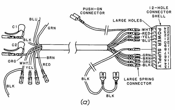
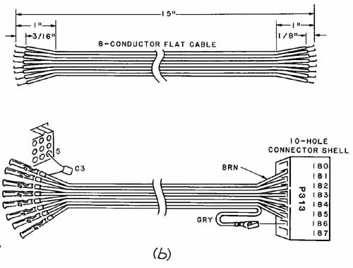
FIG. 16 Details of harness and cable connections: (a) sleeve harness;
(b) flat cable. (Copyright © 1982. Reprinted by permission of the Heath
Company.)
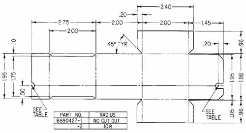
FIG. 17 Pattern layout of a shield for a communications satellite.
(AT&T Technologies, Inc.)
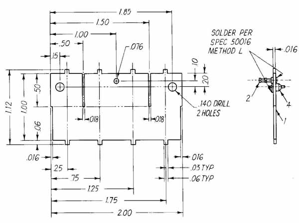
FIG. 18 Manufacturing drawing of a center fin of a chassis. (AT&T
Technologies, Inc.)
12 Chassis Manufacture
Since chassis’ are produced in different shapes, sizes, and complexity, the number of views required for their manufacture will vary. A rather simple U-shaped chassis with a few holes or openings might be well described in two views. More complex ones with many holes or cuts require several views or drawings. The next example illustrates a large, rather complex chassis.
FIG. 19 shows only part of a construction drawing for a chassis like that shown in FIG. 12, with the wiring harness. The complete drawing has four views, plus supplemental drawings showing the exact shapes of some of the holes and other cutouts. Because of size limitations, we have shown only the left quarter of two adjacent views and some of the cutout details, which are placed around the edge of the sheet. The cutout dimensions are given in separate details to avoid cluttering the main views with too much information and to provide a practical way to give the correct tolerances for mounting holes and their components in many situations (Figs. A, C, and D in FIG. 19).
For complete manufacture of this chassis, a separate set of instructions, entitled “Manufacturing Layout and Time Rate,” is issued to the manufacturing section. Some of the 22 steps included in this publication are shown in Table 4-3. Note that even the tools are specified.
This chassis drawing is a typical engineering drawing made to full scale (1 in. = 1 in.). It can be used later on as a basis for an assembly drawing (for putting the rest of the chassis together) and for the harness, or local-cabling, drawing. The advantages of making it to full size are now fairly evident. How ever, chassis for some miniaturized packages cannot be drawn to full scale because they are too small. They must be drawn larger than actual size in order that details and dimensions can be appropriately shown.
More and more layout drawings will use metric dimensioning as the United States slowly converts to SI (Système International d’Unités) in which the base unit of length is the meter. FIG. 20a shows a bracket that is dimensioned in SI and the unidirectional placement of figures, in which all guidelines are drawn horizontally and all numbers and letters are read from the same direction. The unidirectional system has long been approved by ANSI Y 14-4, as has the aligned system exhibited in the previous three examples. Many companies are employing dual dimensioning in the manner shown in FIG. 20b, with millimeters added above the inches. Dimensioning to the nearest millimeter is accurate enough for most manufacturing facilities and equipment. Sometimes more accuracy is needed, in which case dimensions are given to the nearest 0.1 mm.
The plural of chassis is spelled the same way as the singular, which is somewhat confusing. In the above sentence we mean the plural. In the following sentence we are writing about a single chassis. A chassis is a frame, on which something is built or assembled.
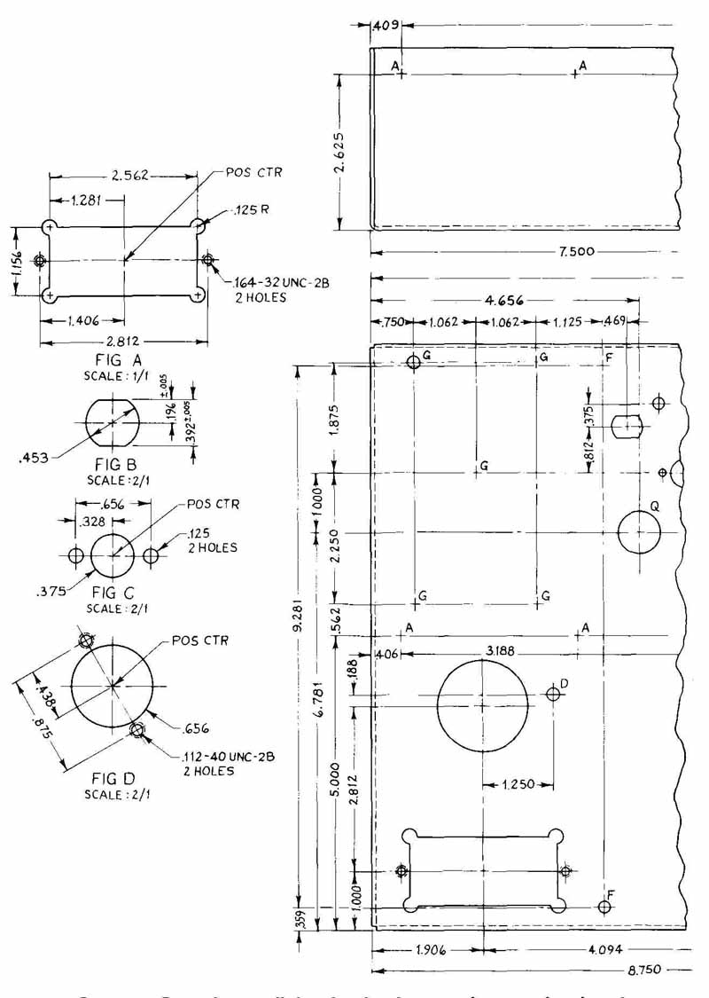
FIG. 19 Part of a detail drawing for the manufacture of a chassis.
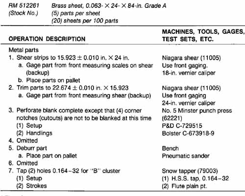
TABLE 3 “Manufacturing Layout and Time Rate”
The detailer or designer must be certain that the manufacturer has metric drills. Otherwise it will be necessary to specify standard U.S. twist drills. The nearest U.S. drill to a 5.00-mm (0.1968-in.) hole is No.9 (0.1960 in.), and the closest drill to a 9.00-mm (0.3543-in.) hole is size T (0.358 in.). Both the metric and the U.S. twist-drill tables are listed in a topical Google search.
13 Hole and Terminal Data
Chassis and wiring boards may be dimensioned according to standard drafting practice. There are several methods in use. Two systems that would be quite suitable for parts containing many holes are shown in FIG. 21. These methods can be used for manual operation of standard drill presses or for numerical control (N/C) machine tools. FIG. 21 a illustrates the type of drawing that is ideal for a programmer to use. Various sizes of holes are indicated by different letters, and the holes within a letter group are numbered sequentially. The xy reference point is located close to a corner, in this case at the center of hole Al. The programmer will be able to write the program (which will later—through tape — give instructions to the machine tool about how to do the job) in a very efficient manner. Holes that are the same size will be drilled one after another. After these holes have been drilled, the drill bit will be changed (manually on some tools, automatically on others) and then the next series of holes will be made.
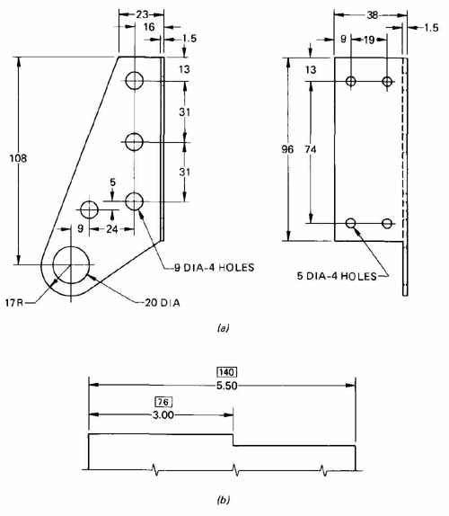
FIG. 20 Metric and dual dimensioning: (a) using millimeters as the
units; (b) dual dimensioning with inches below and millimeters above.
The table in FIG. 21a is so constructed that the absolute method of N/C can be easily performed. However, the other method, called incremental, may also be used by subtracting x and y values of one hole from the next. FIG. 21b also lends itself to both absolute and incremental programming approaches. Actually, it is not necessary to draw the holes on this type of drawing. Some companies follow the practice of showing centerlines only. Holes B 1 to B4 are, of course, threaded. They are No. 10 taps of the coarse-thread (NC or UNC) series having 24 threads per inch. (See table in FIG. 21a.)
Standard threads can be identified in tables such as are found in Appendix D. The unified (UNC, UNF, etc.) series includes standard U.S. threads in inches or fractions. In this table, we find the No. 10 coarse (UNC) thread, with 24 threads per inch, and the fine (UNF) thread, with 32 threads per inch. Either type of thread could be used; the coarse is more common. Another table, which identifies standard coarse and fine metric threads, is also included in Appendix D.
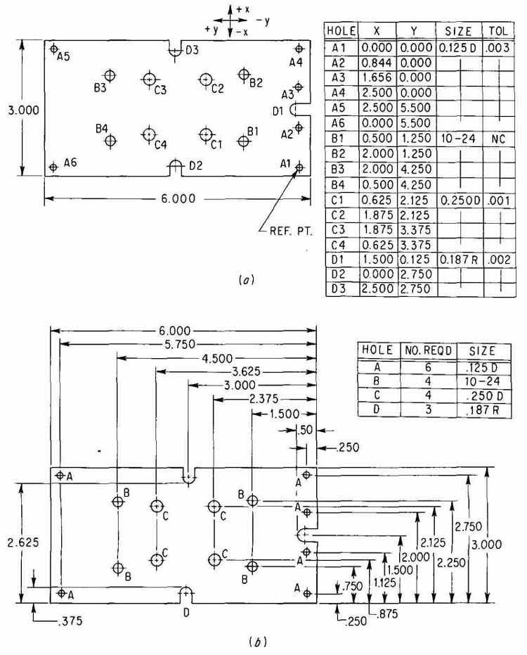
FIG. 21 Positional dimensioning on a drilling drawing: (a) coordinate
system; (b) baseline system.
The pitch of a thread is the distance between the corresponding part of two adjacent threads. For U.S.-English (UNC and UNF) threads, the reciprocal of the pitch (e.g., 24 or 32 threads per inch) is given in the table. But for metric screw threads the pitch is given in millimeters. Thus for a 12-mm thread the pitch for a coarse thread is listed as 1.75 mm, and the fine thread as 1.25 mm.
14 Assembly Drawings
FIG. 22c shows the required components drawn in place on a circuit board. Some reasons for locating the components on such an assembly drawing are:
1. To fit the parts into the space available
2. To satisfy wiring requirements, such as accessibility for connections and short wiring paths
3. To achieve a pattern without crossings if printed circuitry is to be used
4. To satisfy electrical requirements such as shielding, built-in capacitances, etc.
5. To satisfy manufacturing requirements such as assembly by N/C equipment.
Such a layout is made by (1) studying the original schematic, or elementary, diagram to determine what components have common connections, where common lines (e.g., ground, B+) are, etc.; (2) drawing one or more point-to-point wiring diagrams freehand in order to get an optimal arrangement; (3) further refinement, if justified or necessary, which might include cutting out outlines of parts on heavy paper and shifting them into different arrangements; and (4) drawing the final assembly drawing, such as is shown, to scale. Each component is given a designation, such as R (resistor No. 1) and C (capacitor No. 5), or the value, such as 100 for a 1 00-a resistor. The assembly in FIG. 22c was derived from the schematic diagram in FIG. 22a and then by experimentation in the location of components. FIG. 22b represents one start in the layout of components, with the switch and volume control at the front, wires to the speaker and automobile radio at the back. Because the volume control is so bulky and the circuit board and chassis so small (less than 4 in. long), the final layout ( FIG. 22c) includes a recessed portion for R As will be explained in Section 5, the layout was made with a 0.1-in. (2.54-mm) undergnd. Note that all holes (for connection to printed circuitry on the other side) are on the intersections of the grid lines. A photograph of the PC-board assembly is shown in FIG. 23.
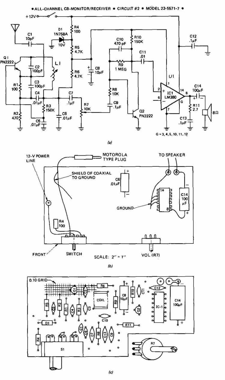
FIG. 22 Steps in the preparation of a CB receiver circuit board: (a)
schematic diagram; (b) trial location of components (incomplete); (C)
final component assembly, or components location, drawing. (Kantronics,
Inc.)
This drawing can be used for two or more purposes: (1) to give a parts-location layout, along with a list of parts and catalog numbers, to production and service personnel and (2) to provide the location of holes for a drilling drawing such as FIG. 21.
Another type of assembly drawing is that used for the assembly of a large chassis itself. FIG. 24 is one such view of such an assembly. The drawing also lists the various parts as follows: (1) chassis (also shown partially in FIG. 19), (2) panel, (3) and (4) angles, (5) brackets, (6) and (7) rivets, (8) grommet, (9) Penn fastener, and (10) self-clinching fastener. (Numbers 7 and 8 are shown on another view.)
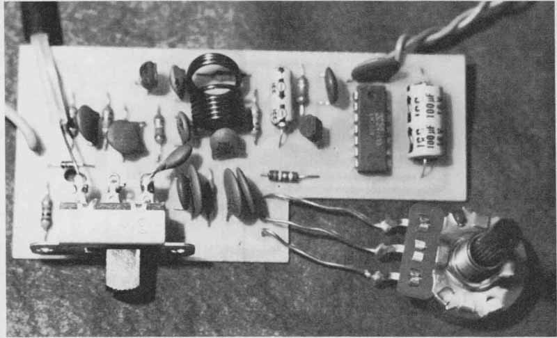
FIG. 23 Photograph of the CB-receiver board which has been drawn in
the previous figure. (Kantronics, Inc.)

FIG. 24 A drawing used for the assembly of parts on a chassis. (AT&T
Technologies, Inc.)
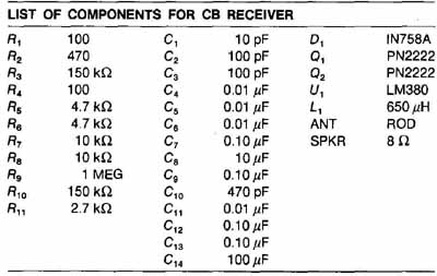
TABLE 4 Parts List: COMPONENTS FOR CB RECEIVER
As in the case of FIG. 19, this drawing is accompanied by a “Manufacturing Layout and Time Rate” sheet which lists each assembly step and the tools with which the operations are to be performed. Chassis are available in various sizes and shapes. Their main purpose is to hold, or support, component parts, but they also often furnish shielding and rigidity and even act as parts of electric circuits.
A parts assembly drawing is usually accompanied by a list of components. Table 4 shows the list of all the components of the CB receiver illustrated in Figs. 22 and 23.
15. Photodrawing
An interesting development in the graphics area is photodrawing. FIG. 25 shows a photograph of an assembled radio with the accompanying letter-number designation of parts. These photographs perform a function similar to that depicted in FIG. 22c. In some ways a photograph is clearer than a drawing. Certain things, like disk capacitors and coils, show up better in a photograph than in a drawing, especially if the assembly is crowded. Electrical installations that have been extensively modified can be shown better by photographs than by well-worn drawings that have had many changes made on them. Numbers for parts identification, alignment symbols, and connection points are drawn directly on the photograph. A complete list of parts usually accompanies a photodrawing.
SUMMARY
Many types of production drawings are used for the construction, wiring, and assembly of electrical and electronic equipment. Examples are connection or wiring diagrams, panel diagrams, chassis layouts, cabling diagrams, and assembly drawings. Connection diagrams are classified as point-to-point, straight- line, highway, or baseline (airline). Careful identification of conductors must usually be made; this may include such items as color, wire size, component and terminal destination, shielding, and function.
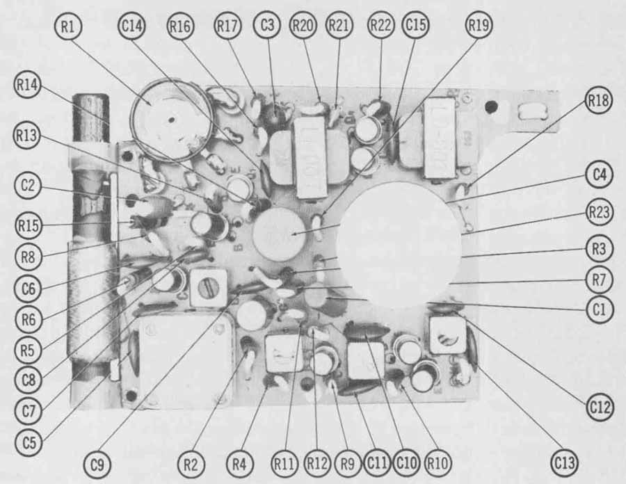
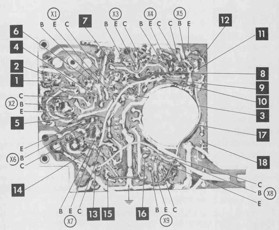
FIG. 25 Photographs of a radio assembly, both sides.
The objects being connected are sometimes shown in pictorial form, symbol form, or elemental (rectangular or circular) form. Interconnection diagrams and cabling diagrams are variations of the connection diagram. Rather detailed drawings may be required to show how the individual wires of a cable or harness are attached to a terminal or connector.
Chassis are necessary to hold the components of an electronic system together and to provide cover, rigidity, and sometimes electrical properties to a circuit. Drawings are used for the manufacture of the assembly itself and are often used as the basis for assembly of the electrical components on the chassis and wiring that is within the chassis area. These drawings usually provide all the information to make the chassis and may be supplemented by complete parts lists and sets of manufacturing instructions. The method of manufacture often dictates how such a drawing is to be dimensioned.
QUESTIONS
1. What are the differences between a point-to-point and a straight-line wiring diagram?
2. What are the similarities between a highway diagram and a baseline diagram?
3. When is it desirable to make a wiring diagram that is pictorial?
4. If a connection diagram is to show such items as switches and antennas, to what source would you refer in order to portray those items?
5. What is the difference between a highway diagram and an airline, or baseline, diagram?
6. Are connection diagrams sometimes accompanied by other types of diagram? If so, what might the other drawing be?
7. Is it true that highways are generally drawn horizontally in a highway wiring diagram?
8. What abbreviations would you use for the colors red, white, orange, slate, gray, green, brown, and blue?
9. What is the sequence, or order, recommended by American National Standards Institute (ANSI) for the identification of feed lines in a highway-type connection diagram?
10. For what reasons would you use different line widths in a connection diagram?
11. Show, by examples, how resistors on each of three different circuit boards belonging to an extensive electrical system would be identified. (Let each resistor be no. 2 on its board.)
12. What is meant by a break-out point in a harness? How would you identify such a point on a drawing?
13. How are fold lines drawn on a flat layout drawing of a chassis?
14. What is the closest metric drill to a No. 16 U.S.-English system drill?
15. What is the diameter in inches of an E-size U.S. drill?
16. What is the diameter of a No. 20 wire? Of a No. 14 wire?
17. What is the number of threads per inch of length of a No. 8 thread or tap for a (a) coarse thread and (b) fine thread?
18. How would you decide how many views to draw for a complete chassis drawing?
19. Before drawing the final components location drawing, what type (or types) of diagram is necessary?
20. If the holes in a chassis, or cover, are to be drilled by an automatic drill (N/C), a table listing the locations and sizes of the holes is made. In what sequence, or order, are the holes arranged in such a table?
PROBLEMS
1. A stereo system is shown pictorially and as a point-to-point diagram in FIG. 2 6. Redraw this as a highway type of connection diagram with at least three highways. For each lead show the following identification: (1) component, (2) terminal, and (3) color of wire. Sheet size: 9 X 12 minimum.
2. Redraw the stereo system shown in FIG. 26 as a baseline (airline) diagram. Use the same identification as specified in Prob. 1. Sheet size: 8.5 X 11 or larger.
3. Redraw the stereo system shown in FIG. 26 as a straight-line diagram.
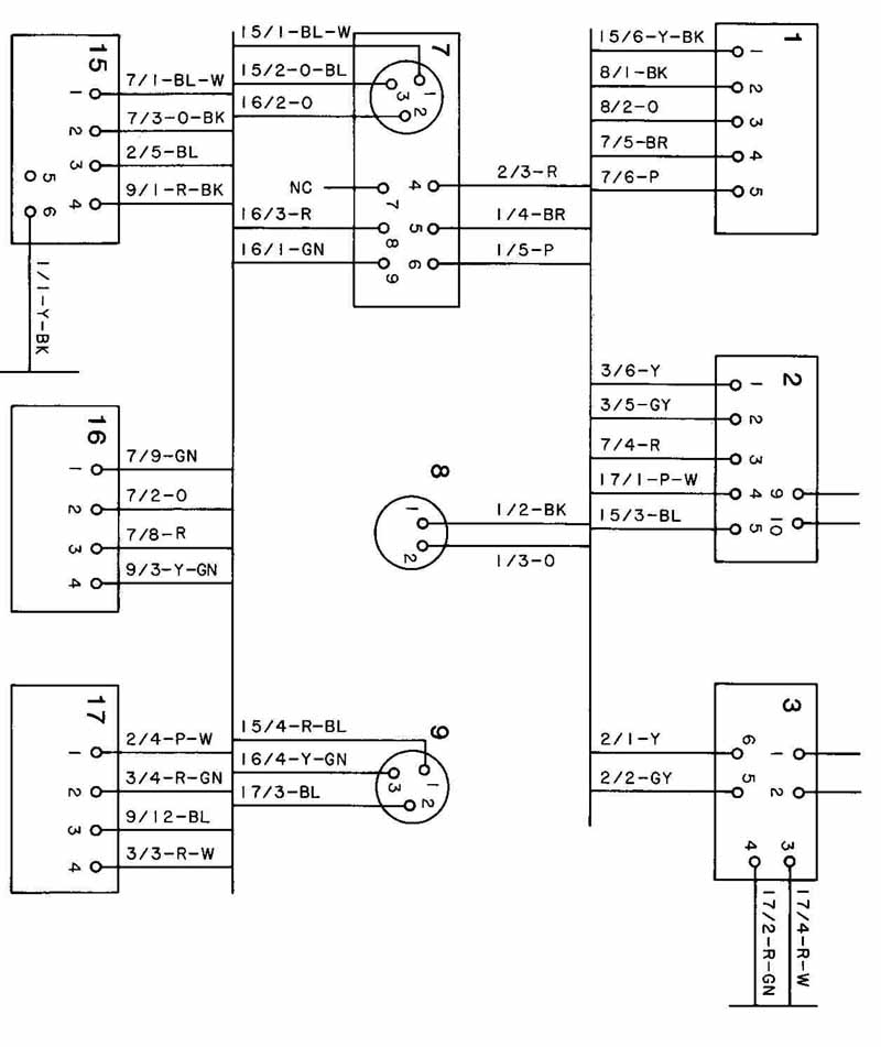
4. Redraw the installation shown in FIG. 27 as a highway-type connection drawing, with at least three highways. For each lead use standard identification as follows: (1) component destination, (2) terminal, and (3) color of wire. For example, the lead from terminal 7 of component 3 would read Dl / l/Y and would be placed near component 3. Drawing sheet size: 11 X 17 or 12 X 18.
5. Redraw the installation shown in FIG. 27 as a straight-line connection diagram. Use standard abbreviations for wire colors. Use 11 X 17 or 12 X 18 paper.
6. FIG. 28 is a baseline diagram of a large-scale amplifier. Redraw this as a point-to-point diagram using the wire colors shown. Use 9 X 12 (minimum) paper.
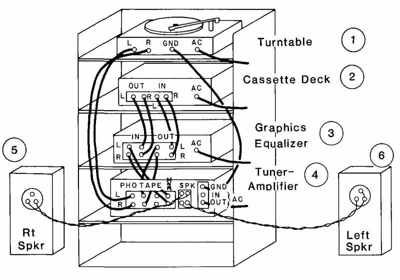
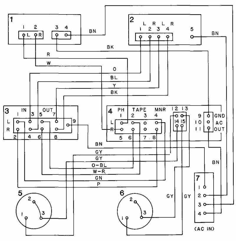
FIG. 26 (Probs. 1, 2, and3.) Pictorial view of the rear of a
stereo sound system and a point-to-point wiring diagram.
7. Redraw the apparatus shown n FIG. 28 as a highway diagram. Use 11 X 17 or 12 X 18 paper.
8. Draw the wiring diagram of the Honda CB 750 as it appears in FIG. 29. This may be improved by using standard symbols for contacts, diodes, etc. and abbreviations for wire colors, such as GN for green and BL for blue. Switching schedules may be included or omitted, as your instructor indicates. Use 11 X 17or 12X l8paper.
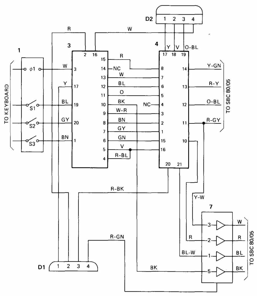
FIG. 27 (Probs. 4 and 5.) Point-to-point wiring diagram of a keyboard-microprocessor
interface.
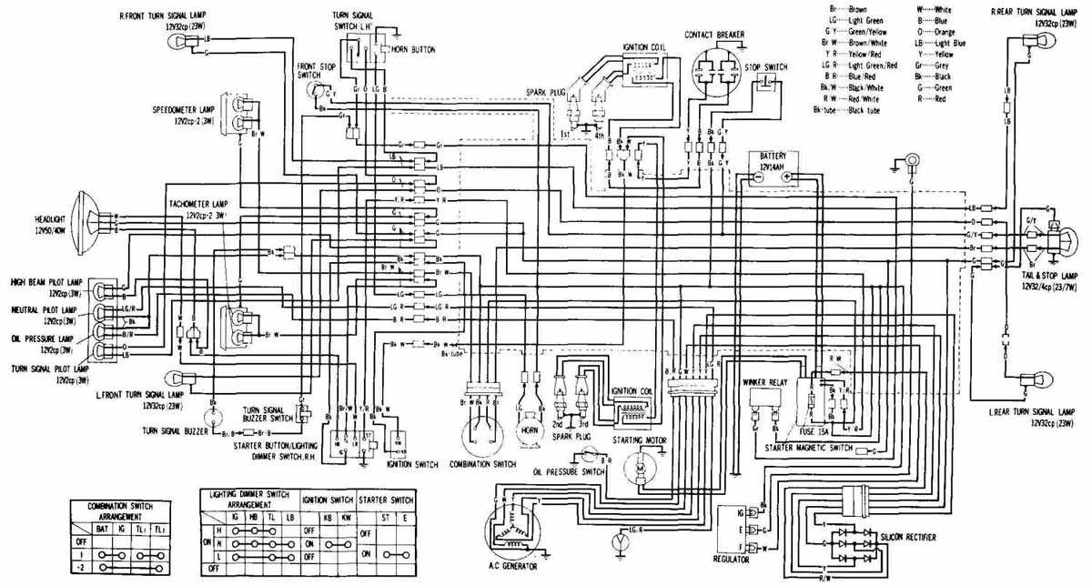
FIG. 29 (Prob. 8.) Motorcycle wiring diagram.
9. The rudimentary diagram of a local-cabling harness appears in Fig. 30. Complete the diagram using the following information:
Since starting line 101 terminates at f in the 400 area, call the termination 401; call the termination of 103, 403; etc. Then add a wire-routing diagram to your drawing. At different places the harness should have different thicknesses, which you should estimate. (Use a 9 X 12 or 11 X 17 sheet.)
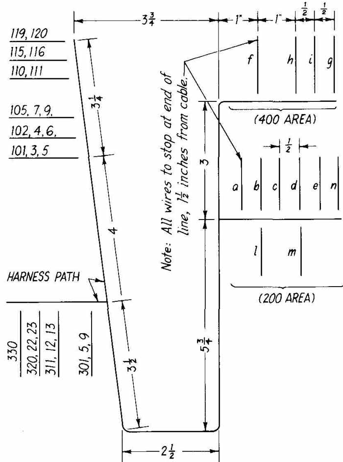
FIG. 30 (Prob. 9.) Cabling harness problem.
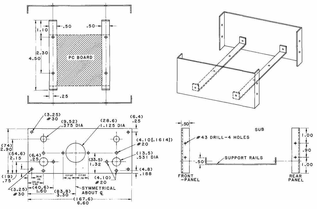
FIG. 31 (Prob. 10.) Orthographic and pictorial views of a subchassis
for an amateur-radio receiver.
10. FIG. 31 shows four views of a subchassis for an amateur-radio receiver. Not shown are a cover and an anodized outside front panel. The front view has dual English-metric dimensioning, whereas the top and side assembly views are dimensioned in inches. Draw to full scale three or four views of this chassis. Use metric, dual, or English system of dimensioning, as your instructor directs. Without dimensioning this will fit on 11 X 17 paper; with dimensioning, on a C-size (17 X 22) sheet, unless scaled down.
11. FIG. 32 shows a pictorial view and partial views of a bracket, plus a schedule for hole sizes. This bracket is part of the assembly shown in FIG. 24. Make a complete drawing for the construction of this part. The bracket is to be made of steel sheet, cold-rolled and commercial quality (CRCQ). The holes and ovals are to be punched out, and “C” holes countersunk for a 0.190—32 flat- head machine screw. The part is to be degreased per Spec. 51606 and zinc- plated for 289A finish. Tolerance is ± 0.016 in. Dimensions may be converted to the metric system. Use 11 X 17 or 12 X 18 paper.
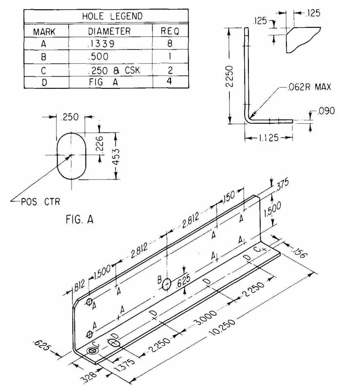
FIG. 32 (Prob. 11.) Bracket for a telecom relay chassis.
12. Make a three-view drawing of the chassis shown in FIG. 33. Flanges A and C are identical. The chassis is to be made of 20-gage (0.95-mm) CR steel and degreased. Finish is to be gray enamel, baked 525A, 0.025 mm thick. Dimension it according to one of the methods prescribed in this Section. One of the views may be a flat foldout, or development. This would permit dimensioning for N/C drilling of the chassis. Dimensioning may be done in the dual or metric system. Dimensions shown are in millimeters. Use 11 X 17 paper.
13. A chassis and cover are shown pictorially in FIG. 34, and the front face is dimensioned below in millimeters. Make a flat layout (development) of the chassis including fold lines (see FIG. 17). Put all dimensions on the figure. Dimension the holes with a table such as that shown in FIG. 21, lower part. Make a set of notes to include the following: material 20-gage 1020 steel; all dimensions in millimeters, tolerance 0.50; deburr all edges; degrease per Spec. 51606. Use 8 X 11 or 9 X 12 sheet if drawn full size. (Dimensions may be converted to inches and the chassis drawn in the English system if requested.) Other views of the chassis may be drawn if your instructor so directs. Diameters of holes are: A, 7 mm; B, 3 mm.
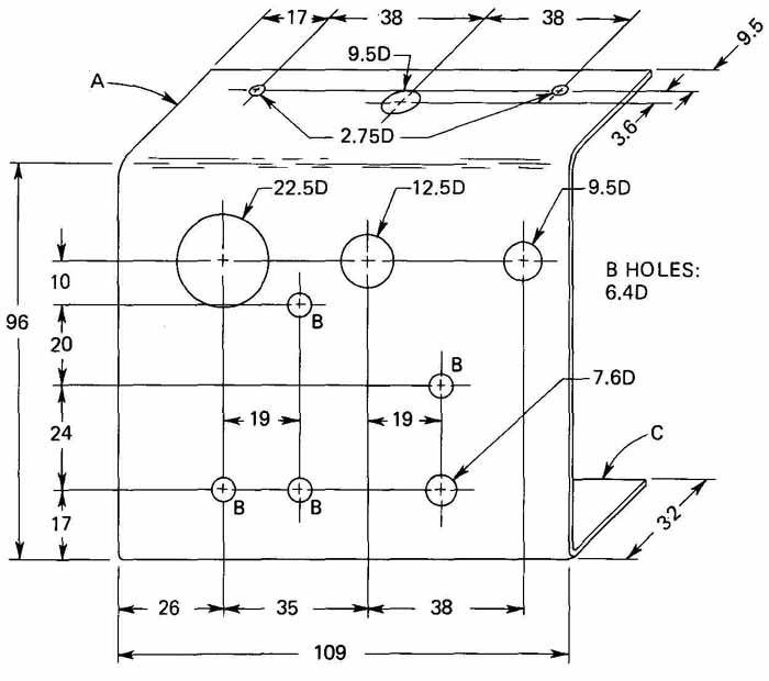
FIG. 33 (Prob. 12.) Pictorial view of a preamplifier.
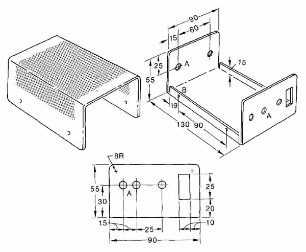
FIG. 34 (Prob. 13.) Above: pictorial view of chassis and cover. Below:
de tailed drawing of front face of chassis. Dimensions are in millimeters.
14. FIG. 35 shows a pictorial view and several other partial views of a chassis. The hole sizes are as given in the table below. Make a complete set of drawings for the construction of this chassis, which has one face labeled A, two panels on each side marked C (each having two holes), and one panel in front labeled B. There is no panel in the rear. Panel B is swung out in the pictorial view to show how C is folded. Panel B is actually vertical. Dimensions are in inches.
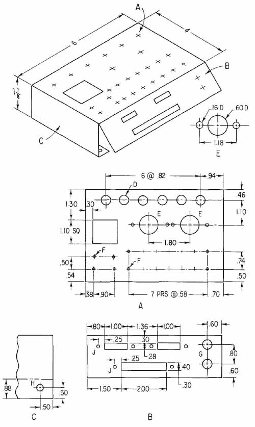
FIG. 35 (Prob. 14.) A chassis drawing problem.
The chassis may be drawn in two ways. Several orthographic views, with dimensions, of the chassis in its completed folded form would be satisfactory. Showing the single piece of metal laid out flat, with fold lines and a small pictorial view of the folded chassis, would also be satisfactory.
All burrs should be removed. The 20-gage steel should be degreased per Spec. 5160 and coated with clear varnish per Spec. 5160. Tolerance is ± 0.02 in. Dimensions may be converted to the metric system. Sheet size: 11 X 17, 12 X 18, or larger.