Here's how these basic building blocks of electronics work.
Almost everything in electronics is built of just a few basic building blocks; resistors, capacitors, coils, diodes and transistors. In this article we'll examine capacitors to see what they are and how they control the movement of electrons in electronic circuits and electronic devices. In the early days of radio, the word "condenser" was used, and it was exactly the same as "capacitor", but today we don't have condensers anymore, just capacitors.
A capacitor consists of just three parts (electrically), It is two plates (metal or other material which conducts electricity) separated by a space which is filled with an insulator, This insulator is called the dielectric. In figure 1-A you can see the symbol for capacitors used in schematic diagrams. It's two parallel lines (representing the two plates) separated by a space.
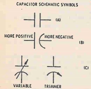
Figure 1. Basic capacitor symbol is (A) above. (B) Shows polarized
capacitor, with negative (curved) line connected to ground. (C)
Shows symbols for adjustable (variable) capacitors.
The editors of ELECTRONICS HANDBOOKS present here a condensed article on the functions of capacitors and their application in the construction of electronic projects.
Much of the material for this article was taken from the Howard W. Sams Co. title "BASIC ELECTRICITY AND AN INTRODUCTION TO ELECTRONICS" for which we extend our gratitude for granting us permission to reprint this material for our readers.
For those readers who are interested, the entire volume of "BASIC ELECTRICITY AND AN INTRODUCTION TO ELECTRONICS" (3rd Edition) may be purchased from Howard W. Sams Co., Inc., 4300 West 62nd Street, Indianapolis, IN 46268 or at most quality bookstores.
Figure 1-B shows the most commonly accepted symbol for a capacitor. Notice that the major difference between this and the previous symbol is that in this symbol one plate is curved while the other plate is symbolized with a straight line. Generally, the curved line indicates the plate that should be connected to a more negative voltage than the other plate. Figure 1-C shows some symbols you may see for variable capacitors or trimmer capacitors used in a variety of electronic applications.
Electrolytic Capacitors
One other important capacitor symbol is shown in Figure 2. This symbol has a "plus" sign next to the "flat" plate. This symbol is the most common one used to signify an electrolytic capacitor. Electrolytic capacitors should always have the plate marked with the "plus sign" connected to a more positive voltage than the other plate. Electrolytic capacitors are designed to be used in dc or pulsating dc applications only.
A variety of other symbols are in use for electrolytic capacitors, and some additional ones are shown in Figure 2. In any of them, however, the polarity of the plates is identified; one of the plates is either labeled positive, or its shape tells you that it is positive.
(Certain specially constructed electrolytic capacitors are available that can be used in ac applications, and the symbol used to indicate these "nonpolarized" electrolytic capacitors is also shown in Figure 2.) If this is your first opportunity to learn about the capacitor, you may be wondering just how the thing works in direct current (DC) circuits. There is no direct conduction path for current flow through the device, so what good is it? Just what does it do? These questions about capacitors will be answered.
First, however, a little discussion of the history of capacitors may be interesting. The fact is that the capacitor was discovered by accident in 1746 in Leyden, Holland by a physicist named Pieter Van Musschenbroek.
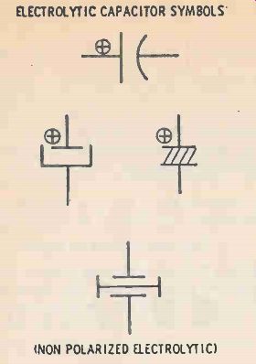
Figure 2. Electrolytic capacitor symbols. One at top is most common.
Tantalum capacitors are a special type of electrolytic.
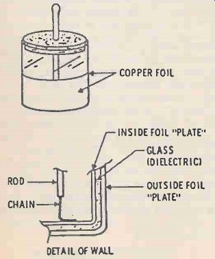
Figure 3. Earliest capacitor was the Leyden jar, consisting of a glass
jar with copper foil inside as well as on outside.
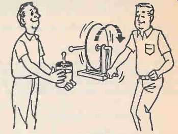
Figure 4. Leyden jar can be charged with electrons by an electrostatic
generator (or from any voltage source).
-------------
Capacitance is Measured in Farads.
So what's a Farad?
The units used to measure capacitance are called farads, named after the scientist Michael Faraday.
Following the equation C=Q/E, a capacitor has 1 farad of capacitance when it can store 1 coulomb of charge with a 1-volt potential difference placed across it.
In reality, 1 farad turns out to be an extremely large unit of capacitance , so most capacitor values are written either in microfarads or in picofarads.
Micro means one-millionth. Pico stands for one millionth of a millionth, or one trillionth! Microfarads are abbreviated as uF, or as uFD, or mF, or mFD. Picofarads are abbreviated as pF, or mmF. The Greek letter "X (which is pronounced "Mu") is commonly used to mean "micro."
-----------------
The Leyden Jar
Pieter was doing some experiments in an attempt to "electrify" water. The water electrification device consisted of a large jar lined inside and out with copper foil as shown in Figure 3. This Leyden jar as it is called, has all of the elements of a capacitor. As shown in the Figure, the rod sticking through the lid of the jar had a chain on the end that hung down and supplied connection to the inside layer of foil. This formed one plate of the capacitor, the glass wall of the jar served as the dielectric, and the outer foil served as the other plate. Van Musschenbroek connected the Leyden jar to a voltage source for a period of time (Figure 4), then the voltage source was disconnected, and the jar removed. At this point Van Musschenbroek's assistant is said to have held the jar with one hand while disconnecting the high-voltage lead with the other hand. The lab assistant received an unexpected shock of considerable intensity (Figure 5). Unfortunately, history didn't record the words spoken by the assistant.

Figure 5. If a Leyden jar (or any other capacitor) is charged to a
high voltage - more than, say 60 or 70 volts - it can give you a shocking
experience. Some capacitors can hold a charge for hours, or even days!
The shock received by the assistant points up a most important aspect of capacitors: They are devices that can store an electrical charge. Electrical energy can be stored or held in a capacitor and then released at a later time. Note that capacitors must be given the charge they store. A capacitor cannot produce electrical energy by itself, the way a battery does with chemical action.
Capacitor Action
How does a capacitor store an electric charge? It does this through the action of an electrostatic field.
To see just how this works, focus your attention on the sketch of capacitor plates shown in Figure 6.
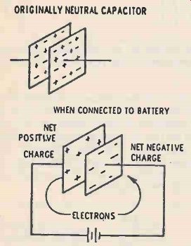
Figure 6. When a capacitor is uncharged it has the same number of
electrons (-) on each plate. When connected to a source of energy (voltage),
electrons collect on one plate until the voltage between plates equals
the voltage of the source (battery).
As you now know, a capacitor consists of two conductors separated from each other by a layer of insulating material called a dielectric. Normally, the two metal conducting plates will have equal amounts of net positive and negative charge. Objects that contain equal amounts of positive and negative net charges are said to be electrically neutral. What will happen to these two plates if a potential difference is applied to them, say with a battery? The negative terminal of the battery pushes electrons out onto the negative connected plate, while the positive battery terminal draws electrons from the positive connected plate. As one plate receives a negative charge due to excess electrons building up, the other plate receives a positive charge due to the lack of electrons created.
The net charges created on the capacitor's plates are equal and opposite. This is an important point. The battery takes electrons from one plate of the capacitor and essentially puts them on the other plate.
Electron Buildup on Plates
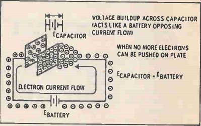
Figure 7. Current flows through connecting wire(s) when a source of
electrons is hooked up to a capacitor
Negative charges (electrons) cannot build up on the negative plate forever. As more and more electrons move toward the negative plate, they start getting pushed back or repelled by the electrons already there. After a while the battery cannot push any more electrons onto the negative plate. The same thing is true with the positive plate. After a while, so many electrons have been removed from the positive plate that the battery cannot pull any more off.
Consequently the capacitor develops a net positive charge on one plate and a net negative charge on the other plate. Because of this, a potential difference or voltage exists between the two plates. At the point where no more charge is flowing the voltage across the capacitor's plates equals the battery's voltage.
Notice in Figure 7 that the voltage across the capacitor opposes the battery's voltage. The capacitor's negative plate is pushing electrons back in opposition to the push of the negative battery terminal, and the capacitor's positive plate attracts electrons and thus prevents their further removal from the positive plate. At the point where the voltage on the capacitor equals the voltage of the battery, no more current flows, since these voltages are in opposing directions.
Capacitor Equivalent Circuit
As you can see in Figure 8, once the capacitor's plates have accumulated enough negative and positive charges, the capacitor acts like a battery wired to act against the original battery in this circuit.
Review in your mind for a moment the important points about a capacitor which have been discussed.
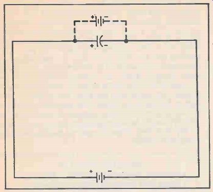
Figure 8. After the capacitor has been charged to the full voltage
of the battery or other voltage source, it (the capacitor) acts just
like a battery (or other source), opposing the further flow of current.
Thus no more current flows in the circuit.
When a capacitor originally having neutral plates is connected to a battery, charge flows as a current exists in the circuit. Electrons flow out of the battery's negative terminal and build up on the negative connected plate, while electrons are drawn from the positive connected plate. The charge created on each plate causes a potential difference or voltage, to build up on the capacitor. As the charge on the capacitor's plates increases, the voltage across the plates increases, until finally the potential difference of the capacitor equals that of the battery. Since these two voltages are in opposition, when they equal each other there can be no more electron current flow. So notice: Electrons flow in the circuit, but none flow through the capacitor because of the insulating gap between the two plates. Also, electron flow or current only goes on for the short time necessary for the voltage across the capacitor to become equal to the battery voltage.
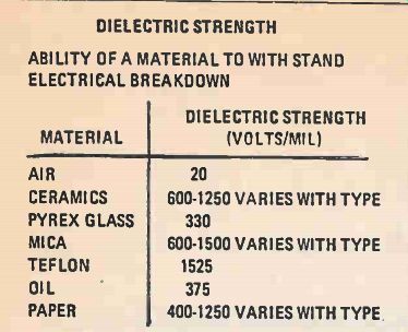
Figure 10. The dielectric strength of materials varies. Air has the
lowest dielectric strength (ability to withstand voltage before arcing
over). Glass can stand much higher voltages (for the same thickness)
and Teflon is able to prevent arcing at very high voltages.
Charged Capacitor
When a net charge exists on each of the capacitor's plates, a potential difference or voltage exists across the capacitor. Likewise, when a voltage is placed across a capacitor, "charge" gets stored inside. Here's an important definition for you to remember: whenever a potential difference or voltage exists between the plates of a capacitor, the capacitor is said to be charged. A primary function of capacitors is this ability to store a charge. Capacitors are rated or measured by how well they perform this function.
The three factors that affect a capacitor's ability to perform the function of charge storage are the size of its plates, the spacing between the plates, and the type of insulating material separating the plates.
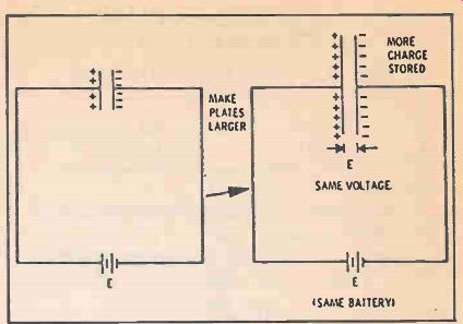
Figure 9. If the plates of a capacitor are made larger (more capacitance)
it will take more electrons (more current) to charge the capacitor
fully--up to the same voltage as the battery (or other source) That's
why larger capacitors store more current.
Plate Area and Capacitance
Each of these factors will be discussed in detail and you will see the first factor, plate size, is the most obvious thing about a capacitor that will affect its charge storage ability. As shown in Figure 9, if each of a capacitor's plates is made larger (that is, the plate area is increased), and then connected to a battery, more charge will be stored on the larger plates than on the smaller plates. More charge would have to flow until the potential difference across the capacitor equals that of the battery. When current flow stops, the capacitor would be storing more charge than a capacitor with smaller plates, even though both capacitors were charged to the same voltage.
Capacitance
Since charge storage is really one of the most basic capacitor functions, a quantity is needed to describe how well a capacitor does this. This quantity is called the capacitance of the capacitor. You have seen, in Figure 9, that the capacitance of a capacitor depends on the area of its plates, the bigger the plate area, the bigger the capacitance. As has been mentioned, there are two additional factors that affect capacitance.
One is the spacing between the capacitor's plates. It turns out that if the plates are pushed closer together, the capacitance will be increased. The third factor deals with the type of dielectric used. If different dielectric materials are placed between the plates, the capacitance will vary. Remember that the capacitance of a device depends on these three things: the spacing between plates, the area of the plates, and the dielectric material (specifically, the dielectric constant of the material.)
Dielectric Strength and Dielectric Constant
Notice that the dielectric in a capacitor is actually doing two things. First of all it is the insulating material that prevents charges from flowing form one plate to the other. Second, dielectric materials because of their makeup, actually act to help the capacitor store charge. As different dielectrics are placed between the plates of a capacitor, its capacitance will vary.
Two special quantities are used to describe how well a dielectric performs these two functions. One is dielectric strength. This describes how resistant to breakdown a dielectric is. In capacitors, dielectrics consisting of very thin sheets are often subjected to very high voltages. When the voltage applied across the dielectric becomes high enough the dielectric will "break down," and electrons will "punch their way through" the dielectric. This creates a conducting path from one plate to the other through the dielectric and the capacitor malfunctions. Dielectric strength is a measure of how resistant a dielectric is to this type of breakdown. The dielectric strength of a material is commonly measured in volts per mil (V/mil); and some common values are listed in Figure 10 (One mil-1/1000th of an inch). These values tell you how many volts a one-mil thickness of dielectric can withstand before breaking down.
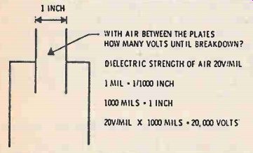
Figure 11. The voltage that a capacitor can withstand before it breaks
down (arcs over) depends both on the spacing between the plates and
on the dielectric strength (material) of the dielectric between the
plates.
For example, the dielectric strength of air is 20 volts/mil. How many volts would be required to break down 1 inch of air and jump a spark through it? As 1 mil is 0.001 inch; so 1 inch is 1000 mils. Air can withstand 20 volts for each mil of thickness so 20 volts/mil times 1000 mils equals 20,000 volts. In a capacitor with 1 inch of air between its plates, 20,000 volts applied would be enough to cause breakdown as shown in Figure 11.
Dielectric Constant
The other factor of importance that describes how well a dielectric functions in a capacitor is called its dielectric constant. This is a measure of how well a dielectric helps a capacitor store charge. Dielectric constants for some common materials are listed in Figure 12. Notice that the dielectric constant for air is listed as 1. The dielectric constant for any other material tells you how much more (or less) effective a material is (as compared to air) in helping a capacitor store charge. Glass, for example, has a dielectric constant of 8. If you had a capacitor with air originally between its plates, and replaced the air with a glass slab of the same thickness, the capacitor's ability to store charge would have increased 8 times. Just how dielectrics work to help capacitors store charge has to do with how they affect the electric field between the capacitor's' plates.
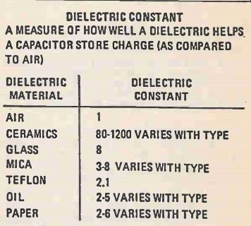
Figure 12. The material used between the plates (the dielectric
material) determines how much energy (current) can be stored by a
capacitor. An air-dielectric capacitor, such as is used in AM radios,
can store the least energy. Other materials store much more energy,
for the same area and the same spacing between plates. DIELECTRIC
CONSTANT A MEASURE OF HOWWELL A DIELECTRIC HELPS A CAPACITOR STORE
CHARGE (AS COMPARED TO AIR).
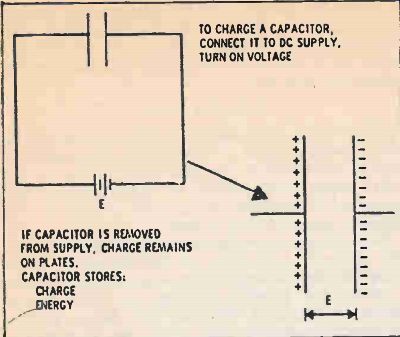
Figure 13. When the voltage (energy) source is removed or disconnected
from the capacitor, the energy (electrons) remain stored on the plates
of the capacitor until they are reconnected by a wire or other circuit
components, as in Figure 14.
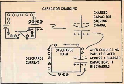
Figure 14. At the left, above, the capacitor is charging while connected
to an energy source (battery). At the top right it's been disconnected,
but is storing (holding) its charge. At the bottom right, connection
through a circuit has been made across the charged capacitor, and the
energy (electrons) rush back around through the circuit (wires or components)
to equalize the charge on the two plates of the capacitor.
Capacitor Charging
As you remember, from the story about the lab assistant who discharged the Leyden jar (Figure 5!), if you want to charge up a capacitor, you must connect it to a supply of DC (direct current) and apply a voltage. After a very short while, current stops flowing and the plates have a potential equal to the supply voltage.
An important point: if the capacitor is disconnected from the battery or supply while in its charged condition, the charge still remains on its plates. How does the capacitor hold this charge on its plates? The first law of electrostatics states that unlike charges attract each other. Look at Figure 13, and you can see that even with the battery disconnected, the positive charges on one plate will attract the negative charges on the other plate and hold them there.
Because of these unlike charges on the plates, an electric field exists in the dielectric region between them. This field is actually the mechanism that holds the charge on the plates, and also while acting to do that, actually stores energy. Since this electric field exists in the dielectric in the absence of current flow, it is called an electrostatic field.
Since the charges on the plates cannot move to reach each other because of the insulating dielectric between the plates, in its charged condition the capacitor can store charge and energy for long periods of time. This means that a charged capacitor can be used to provide a current or do some work for you at some later time.

Figure 15. This table shows all the common types of capacitors with
their widely different characteristics. Air, mica and ceramic types
are most often used in radio frequency circuits. The other types are
more often used in audio frequency and power circuits.
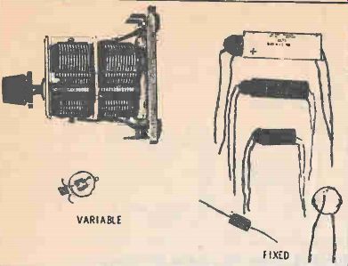
Figure 16. Two types of variable capacitors are shown here. The top
is a common tuning capacitor for AM radios. It's actually two (ganged)
separate capacitors using air dielectric. Below it is a trimmer capacitor,
often used to optimize car radio antennas.
Discharging a Capacitor
Remembering the Leyden jar and how it was discharged, the electrical energy (charge) which is stored in a capacitor may be recovered if a conducting path is provided between the plates. This procedure is called discharging the capacitor. The excess electrons on the negative plate will flow to the positive plate, until both plates have no net excess charge, or are neutral. In this condition, the capacitor is said to be discharged. The current that flows is called the discharge current and the path taken by the current is called the discharge path. A charged capacitor may be discharged by providing an appropriate conducing path between its plates as shown in Figure 14. An important observation for you to make should be emphasized at this point. Even though the power may be shut off to a circuit, every capacitor in the circuit may retain its charge for a long period of time. Therefore, before working on high voltage electronic circuitry, you should be sure to discharge all capacitors. The stored charge and energy in capacitors can discharge through you giving you a nasty shock. Ask Pieter Van Musschenbrock's lab assistant!
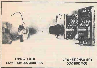
Figure 17. At left is a paper capacitor partly disassembled. At the
right a two-section air tuning capacitor is shown partly opened (to
less than full capacity).
Charge Formula
The amount of charge present on the capacitor's plates and the voltage across the plates are related.
To restate, the capacitance of a capacitor in farads equals the charge on the capacitor in coulombs divided by the voltage across it. or C- - - -Q/E This equation may now be rearranged to be shown as C2=CE, or the charge stored in a capacitor (in coulombs) equals its capacitance (in farads) times the voltage between its plates. Look at this new equation carefully. It states that the amount of charge stored in a capacitor is directly related to the voltage across the plates, the more charge on the plates, and vice versa. For a given voltage, the higher the capacitance, the more charge will be stored on the plates, and vice versa.
Capacitor Types
Now that you have seen a bit about how capacitors work, consider some of the actual components you may find available in the laboratory. Figure 15 is a chart listing various types of capacitors that are available. Capacitors are usually named by the dielectric material used in them.
Because of the many applications of capacitors and the different properties of the dielectric, each capacitor you encounter will probably be labeled with a WVDC or "Working Voltage dc." This is the maximum voltage the capacitor can tolerate without its dielectric breaking down. As you apply capacitors in circuits, the voltage across them must be kept well below this WVDC.
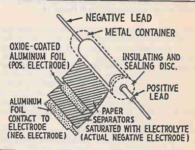
Figure 18. An electrolytic capacitor is shown in this diagram. Tantalum
capacitors are similar, with tantalum foil plates instead of aluminum
foil.
Fixed and Variable
Capacitors are available in both fixed and variable types as shown in Figure 16. Several different common types including paper, mica, and ceramic capacitors are shown in the figure. As mentioned, these are named for the dielectric material employed in manufacturing them, and are produced in a set of preferred values, with tolerances similar to those of resistors.
Construction
To keep the size of these devices as small as possible a series of foil plates is usually employed with thin sheets of dielectric rolled up in between them as shown in Figure 17. Also shown in the figure is a typical variable capacitor. Variable capacitors are most often constructed so that their effective plate area can be varied by rotating a shaft connected to one set of plates. These plates can be moved between a stationary set of plates changing the capacitance value of the device.
Electrolytics
Many electrolytic capacitors are manufactured from two aluminum sheets separated by a saturated paper layer (Figure 18). The paper is saturated with a special chemical called an electrolyte, and rolled together with the aluminum sheets and packaged in a compact roll. When the capacitor is manufactured, a dc voltage is applied to it causing a thin oxide layer to be formed on one sheet. This oxide is very thin and acts as the insulating dielectric between the two plates. One of the capacitor's plates is now the aluminum sheet with the oxide deposited on it (positive plate), and the other plate is actually the electrolyte, which is connected to external circuits by the second aluminum sheet. Since the oxide layer is extremely thin, very large capacitances are available in electrolytic form. Since the oxide is fairly fragile, only lower voltages can normally be used with electrolytics. But most important, because of the way electrolytic capacitors are constructed, they can never be used in ac applications. They are restricted to only dc or pulsating dc applications, and must always be wired into dc circuits in the correct polarity, positive terminal to more positive voltages, negative to more negative voltages. If wired in the opposite direction, the electrolytic behaves as a low-value resistor, and the capacitor may actually explode due to heat generated by large amounts of current flow through it.
A subgroup of electrolytic capacitors are called tantalum because they use tantalum instead of aluminum alloy for their plates.
Electrolytic vs Oil-Filled
Often in electronics, large amounts of capacitance may be needed in a small space. Most standard fixed capacitors are limited to values of about 1 microfarad or less due to cost and size considerations. There are capacitors available, however, that use a special chemical action to cram a large amount of capacitance into a small space. These are called electrolytic capacitors. An electrolytic capacitor having a capacitance of 42,000 microfarads may be about the same size as a 10 microfarad standard oil filled capacitor. A price is paid, however, because the maximum working voltage of electrolytic capacitors is usually much lower than oil-filled or other standard types. As mentioned, the maximum working voltage or WVDC of a capacitor is affected by its plate spacing and dielectric. If voltages on the capacitor's plates are higher than the WVDC, the dielectric will usually break down, allowing charge from one plate to pass through the dielectric to the other plate. When this happens, the capacitor is no longer properly functioning. With severe breakdown, the plates may actually short together, rendering the capacitor useless. A good rule of thumb is to choose capacitors that have a working voltage well above the highest voltage with which they will come in contact.
Also see:
More from EH magazine: Tandy's Radio Shack
Adapted from: Electronics Handbook--Spring 1987