The best way to become proficient at working with electronics is (you guessed it) to use electronic parts (components) in actual working circuits that have useful functions. Most of the projects in this "Workbench Projects" section are relatively simpler or have fewer parts than the other project sections of this magazine, so this is a good place for the beginners to start After you've successfully assembled one or two of our Workbench Projects, you are ready to go on to more complex projects, which you will find in the "IC Testbench" and the "Circuit Fragments" sections of this issue. You'll probably find several that you can apply to good advantage after putting them together and you'll have an opportunity to learn more about a rewarding hobby and a favorite subject of ours the ever-expanding world of electronics.
If you haven't had much experience building electronic projects, there are a few things that you should know and be sure to keep in mind during your construction. These are detailed earlier in this issue under the title "Getting Started With Electronic Projects". We urge you to read this carefully before you begin any actual assembly... .good luck and have fun.

-------------
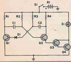
EMERGENCY FLASHER
PARTS LIST FOR EMERGENCY FLASHER
B1-6-volt lantern (heavy-duty) battery
C1, C2-1.0-uF 25-VDC non-polarized mylar capacitor
D1-1N4002 diode
L1-#82 lamp rated 6,5 VDC @ 1-amp
Q1, Q2, Q3-2N3904 NPN transistor
Q4-2N3724A NPN transistor
R1, R4-10,000-ohm, 1/2 -watt resistor, 5%
R2, R3-390,000-ohm, 1/2-watt resistor, 5%
S1--SPST toggle switch
For camping or highway emergencies, here is a solid-state light flasher that's compact and reliable.
Q1, Q2 and the associated resistors and capacitors comprise a conventional 2-transistor multivibrator.
Q2's emitter signal drives the Q3-Q4 Darlington pair, which turns on high-current lamp L1. The light flashes on for about 0.4-second, then darkens for about the same period of time before turning on again. Power for the circuit comes from a standard 6-volt lantern battery. You could probably build the entire flasher circuit inside the housing of your lantern and actuate it only when necessary. If longer battery life is desired, and decreased illumination is acceptable, you could substitute a less power-hungry 6-volt lamp for L1.
-------------------
Capacitor TESTER
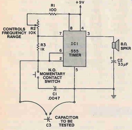
Capacitors in the .002 to .007 mf range are not large enough to produce an audible tone from the speaker.
But, when R2 is set to maximum and switch S1 is pressed, adding C1 in parallel to the value of the capacitor to be tested, the two combine to form a capacitance that is just large enough to produce a very high audio tone from the speaker.
Capacitors above 50mf tend to produce a clicking sound from the speaker when R2 is set to minimum. R1 is placed into the circuit as a safety feature to keep things from shorting out when R2 is set to minimum.
This tester does not show the values of the capacitors being tested. It simply shows if they are good or bad, which is all that is important when you are checking a board for bad components.
The tester is very simple to build. The layout is straightforward and placement is not critical. You can use circuit boards, or use point to point on perf boards.
The author used an old circuit board after removing the old components from it. The 9 volts D.C. can come from a battery, or power supply. Here, we have 9 volt battery eliminator that is clipped to the proper circuit board leads and plugged into the wall. No cabinet was used (wasted effort and expense). Over 200 capacitors in the .002 to several hundred mf range were tested. Of these 12 were thrown away because the tester has shown them to be bad.
For compact size and sturdiness, we have placed the variable resistor R2, the switch Si and the speaker (small 2 inch size) all on the same board as the 555 timer.
PARTS LIST
R1-100-ohm
R2--10+KO variable
R3-11")
IC1--555 Timer
C1--.0047 mf
C2--33 mf
C3-capacitor to be tested
S1--N.O. momentary contact
MISC. 8 ohm 2-3" speaker
Test leads probe tips or clips.
--------------
THIRD DEGREE TESTER
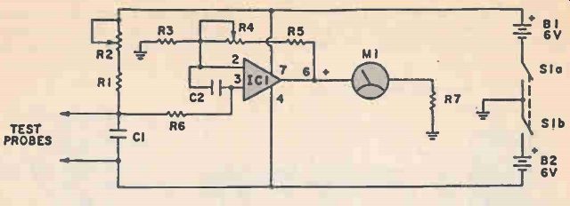
When a person is under mental stress one of the physiological changes includes a lowering of the body's skin resistance and one of the characteristics measured by the modern lie detector is skin resistance.
Our lie detector work the same way: it measures the body's skin resistance. In typical use you would connect one test probe, actually a length of non insulated wire taped to the skin, to each hand, arm, or wrist, adjust control R2 for a meter null (zero meter reading) and then ask your questions. If a question causes the subject mental stress you will usually see this stress indicated by an increase in the meter reading.
Potentiometer R4 serves as a sensitivity control.
To avoid pinning the meter start with R4 at about the mid position: increasing the resistance increases the gain, while decreasing the resistance reduces the gain and the meter reading.
To avoid taping the probes to the person under interrogation get a pair of the metal clips used to secure trousers cuffs by bicyclers. They're available at sporting good stores, department stores, if they sell bicycles and at bicycle shops, of course.
Solder the test probe wires to the clips (or wrap well with bare wire, if they're stainless). Then bend the clips to fit the arm(s). Wipe the skin with alcohol to make better skin contact.
If long test probes are used (More than 3-feet long) use shielded wire to cut down hum pickup.
Connect each shield to chassis ground (where switches S1a and S1 b meet) or use two-conductor shielded wire, then fan conductors out a foot or so at the probe end.
PARTS LIST FOR THIRD DEGREE TESTER
R1, R5-10,000-ohms
R2, R4-1 megohm potentiometer
R3, R6-1,000-ohms
R7- 560-ohms
C1, C2- 0.01-uF, 25 VDC or higher
IC1-Operational amplifier, type 741
S1 -Switch, DPST
B1, B2- 6V or 9V battery, Burgess Z4 or equiv.
M1- -Meter, 0-1mA DC
-------------------------
SLOT CAR REFEREE
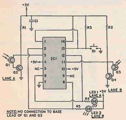
Build this opto-electric judge and end forever those quarrels over who really won the race. Install phototransistors Q1 and Q3 at the finish line, but in separate lanes of your slot-car track so that the light-sensitive face of each device is facing upwards. The best method would be to cut a small hole into the track for each phototransistor, and mount each unit flush with the track's surface.
Arrange for light to fall on both Q1 and Q3; a small desk lamp will work well, but ambient room light will usually suffice. Press S1 and both LEDs will go off. The first car to cross the finish line interrupts the light beam and the appropriate LED to light up.
PARTS LIST FOR SLOT CAR REFEREE
C1--0.1-uF capacitor, 35 VDC
IC1--7474 dual D-type flip-flop
LED1, LED2--light-emitting diode
Q1, Q3-- FFT-100 NPN phototransistor
Q2, Q4--2N3904 NPN transistor
R1, R2--18K-ohm resistor
R3--3900-ohm resistor, R5-330-ohm resistor
S1--normally open SPST pushbutton switch
--------------
CLOCK DIVIDER
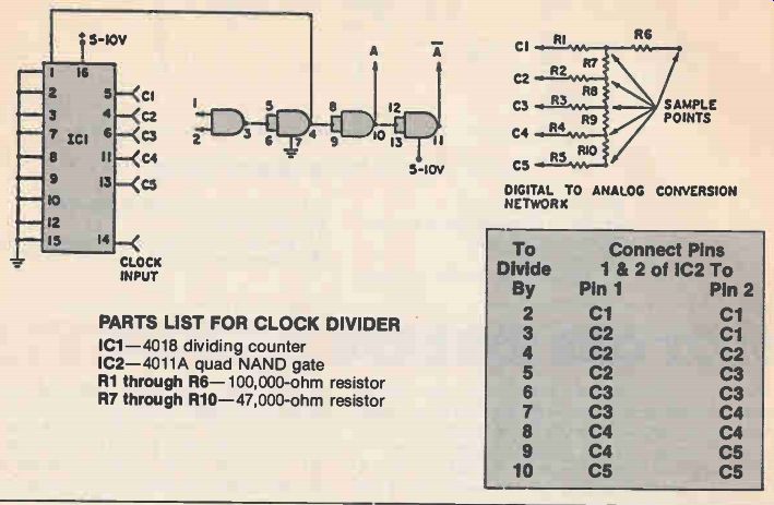
The type 4018 programmable counter is a useful digital tool, especially where a basic clock frequency must be divided down for various timing operations. With proper connections, divisors of from 2 through 10 may be configured. The table shown gives the connections. The odd divisors do not give symmetrical outputs, but close ratios, such as four-high, three-low for a divide by-seven setup. Digital-to-Analog Conversion may also be studied by connecting the outputs as shown.
Interesting waveforms may be obtained by trying out the various dividing connections, while tying an oscilloscope into the different resistor network junctions. With the circuit set for a divide-by-ten function, a digital sine wave may be discovered at certain points along the network. With clock frequencies above 1 KHz, this output may be heard on an audio amplifier. Computer Music, anyone?
PARTS LIST FOR CLOCK DIVIDER
IC1--4018 dividing counter
IC2--4011A quad NAND gate
R1 through R6--100,000-ohm resistor
R7 through R10--47,000-ohm resistor
------------------
BETTER THAN A BREATHALYZER
-------- PARTS LIST FOR BREATHALYZER
C1- 250-uF electrolytic capacitor, 35 VDC
C2- 50-uF electrolytic capacitor, 35 VDC
IC1-LM3914 LED display driver
LED1 through LED 10--light-emitting diode
R1 - 50K potentiometer
R2-5600-ohm resistor
R3-33K-ohm resistor
R4- 47- ohm resistor
R5-18000-ohm resistor
R6-1000-ohm resistor
S1- normally closed SPST pushbutton switch
S2- SPST toggle switch
S3- normally open SPST pushbutton switch
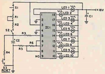
It's curious and unfortunate fact, but many people feel that a drink or two will improve their reflexes. Here's your chance to prove them wrong.
Imagine for the moment that S1 is depressed (open circuited) S2, is closed and C2 has been completely discharged. On command from someone acting as the tester, the person depressing Si must remove his hand from that switch and use the same hand to open toggle switch S2. When S1 is released, charging current begins to flow into capacitor C2 through R1 and R2. This current is interrupted, however, as soon as S2 has been opened. C2 will have accumulated a voltage directly proportional to the reaction time, which is the interval between S1's release and the opening of S2. Longer times create higher voltage and cause higher-numbered LEDs to light. For example, a sober person might react quickly enough to light LED 2 or LED 3, while someone truly sloshed will light up LED 10. To run another test, discharge 02 with S3, then press S1 and, finally close S2 once more. R1 should be adjusted so that a sober person lights one of the low numbered LEDs.
----------------------
LET'S PLAY DOCTOR
Ausculation is the medical term for the procedure. In simple language, it means having your ribs tickled with an icy cold stethoscope.
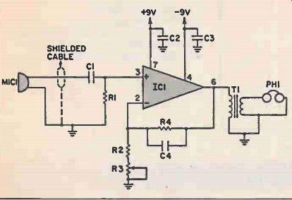
Should you ever get the urge to play doctor, we prescribe the simple electronic stethoscope diagrammed here. Best results will be obtained using hi-fi or communications-type low impedance headphones designed to isolate the listener from ambient sounds. Be sure to connect the micro phone cartridge to the rest of the circuit using shielded audio cable to keep noise pickup to a minimum. Potentiometer R3 adjusts the gain. Use a socket when mounting IC1 since it has delicate FET inputs.
PARTS LIST FOR LET'S PLAY DOCTOR
C1 -0.01-uF capacitor, 35 VDC
C2, C3--0.1-uF capacitor, 35 VDC
C4-10-pF capacitor, 35 VDC
Id -RCA CA3140 op amp
MIC1--ceramic mike cartridge or small ceramic mike
PH1 -low impedance (Hi-Fi) Headphones
R1, R4-1 Megohm. 1 / 2 -watt resistor, 10%
R2-1000 ohm, 1 / 2-watt resistor, 10%
R3 -10K linear-taper potentiometer
T1 -miniature audio output transformer (500 to 1000 ohms primary)
-------------------
MAGIC BLINKER
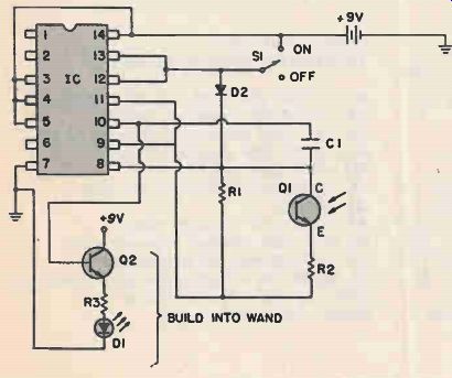
Imagine a small black box that you place on a table in front of your friends. Connected to the box with a thin wire is a wand with a small red light (LED) on the end. The light flashes about twice a second, but at your command, it flashes faster and faster. You hand it to your friends, but they cannot do it. The secret? In the box is a small hole with photo transistor Q1 showing through, As D1 gets closer to 01, it flashes faster and faster but it will take your friends a long while to catch on. It's especially effective when all the room lights are out. Have fun.
PARTS LIST FOR MAGIC BLINKER
C1--0.01-uF capacitor, 15 VDC
D1--small LED D2-1N4001 diode
IC1--4000 dual Nor gate w/inverter
Q1-FPT100 phototransistor
Q2-2N4401 transistor
R1--1 megohm resistor
R2--5 megohm resistor
S1--SPST switch
--------------------
REACTION TIME TESTER
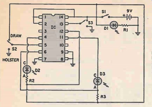
The object of this tester is to test your reaction time against your opponent's. A third person acts as referee and begins the duel by pressing Si, which lights LED D1. Upon seeing D1 lit, you try to outdraw your opponent by moving S2 (or S3) from "holster" to "draw" before he does. If you do, D2 ( or D3 if you use S3) will light first and will automatically prevent the other LED from lighting.
A clear winner every time!
PARTS LIST FOR REACTION TIME TESTER
D1, D2, D3,-large LEDs
IC1--4011 NAND gate
R1 -2,000-ohm resistor
R2, R3-1,000-ohm resistor
S1 -pushbutton (doorbell) SPST switch
S2--toggle-type SPST switch
S3-toggle-type SPST switch
-------------------------------------
TELEPHONE EAVESDROPPER
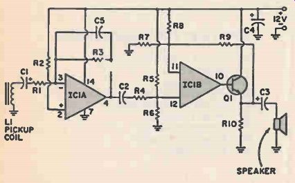
You can pick up and amplify the voice signals from your telephone by using this simple IC circuit and a small pickup coil. The circuit has sufficient output to drive a loudspeaker. One section of a quad op amp is used as a high-gain voltage amplifier. This increases the relatively low output of the pickup coil ( a few millivolts) to a sufficient level to drive the loudspeaker. The circuit draws about 60 milliamperes from a 12 volt power source.
You can purchase a ready made pickup coil or construct one yourself using about 200 turns of fine enamel wire wound around an iron core. Place the pickup coil near the telephone receiver for best results.
You can also record the phone calls by tapping off the output signals at C3 and feeding it to your tape recorder.
------- PARTS LIST FOR TELEPHONE EAVESDROPER
C1 -10-uF electrolytic capacitor, 25VDC
C2-.01-uF disc capacitor, 15 VDC
C3, C4--15-uF electrolytic capacitor 15 VDC
C5-.001uF disc capacitor,15 VDC
IC1 -3900 quad amplifier
L1--inductance pickup coil (see text)
Q1 -2N4401
R1--1,000-ohm, 1/2-watt resistor
R2, R4-1,000,000-ohm, 1/2-watt resistor
R3-470,000-ohm, 1/2-watt resistor
R5, R6, R8, R9-10,000,000-ohm, 1/2-watt resistor
R10-100-ohm, 1/2-watt resistor
SPKR -8-ohm PM speaker
---------------------
AUTOMATIC NITE-LITE

It's automatic! Let the face of Q1 get dark and L1 turns on. Phototransistor Q1 turns on buffer switch Q2-03, which activates Darlington switch pair Q4 and Q5 to turn on 11. 11 is current limited by R4 to deliver long life and reduce the circuit's overall current drain.
Don't make the mistake a brilliant engineering school made years ago. They installed a sophisticated system based on a circuit much like this. It was designed to turn their area lights on at dusk, off at sunrise, and had delays built in to keep the lamps from flickering when a cloud for example, temporarily blocked the sun. The mistake came when they placed the circuit at the bottom of the light poles. The first night the lights came on fine, but after a delay the circuit mistook them for sunlight and turned them off again. Which started the whole process over and had the campus blinking all night.
PARTS LIST FOR AUTOMATIC NITE-LITE
B1-9 VDC battery 11-Bulb, #47 – type
Q1--Photoelectric transistor, FPT 100
Q2, Q3--NPN transistor, 2N3904
Q4, Q5-PNP transistor, 2N3906
R1 - 10-Megohm resistor
R2-1000-ohm resistor
R3-100,000-ohm resistor
R4-27-ohm resistor
S1-SPST switch
---------------------
WHITE NOISE GENERATOR

PARTS LIST FOR GENERATOR
C1 - 0.005-uF capacitor, 15 VDC
C2, C3- 10uF electrolytic capacitor, 15 VDC
C4-75-uF electrolytic capacitor, 25 VDC
IC1-741 op-amp
Q1- 2N4401
R1-100,000-ohm linear taper potentiometer
R2, R6- 10,000-ohm
R3, R4-4,700-ohm
R5 - 1,000,000-ohm
SPKR-(3.2 to 8 ohm) speaker
T1--audio output transformer (500 to 1000 ohm primary)
Noise, more or less "pure white" from some source of uncertainty can be filtered and shaped for various purposes, ranging from radio alignment to music or the simulated sounds of rain on the roof. There are various naturally random impulse sources available to the experimenter, including the plasma from gaseous discharges occurring in neon lamps. On the semi-conductor level here are diodes and transistors purposely configured and biased into noisiness. But under certain conditions, many semiconductor junctions develop wide band RF noise. When amplified by a type 741 op amp, which has internal frequency roll-off elements, the result is a continuous hiss in the output speaker, simulating rain. The signal can also be used in the development of "electronic music" and the testing of hi-fi filters and systems.
Also see: IC Testbench
More from EH magazine: Circuit Fragments
Adapted from: Electronics Handbook--Spring 1987