AMAZON multi-meters discounts AMAZON oscilloscope discounts
After studying this Section, you will be able to:
- Identify components by symbol.
- Read the resistor color code.
- Correctly draw component symbols with a template.
- Correctly reference components.
- Correctly write component values.
Electronic circuits are normally made up of individual components. The drafter’s knowledge of these components, their symbols, and references is mandatory. You need to know these important facts so you can represent the components in a schematic. The engineer will design the circuit and analyze its feasibility.
After completing the engineering task, a sketch of the circuit will be submitted to drafting. Drafting will use the sketch to create a formal schematic drawing. The drafting department is responsible for making sure each component is correctly shown. To do this, you need to be familiar with the following standards:
1. Y32.2 ELECTRICAL AND ELECTRONICS DIAGRAMS, GRAPHIC SYMBOLS for.
2. Y32.14 LOGIC DIAGRAMS, GRAPHIC SYMBOLS for.
3. Y32.1 6 REFERENCE DESIGNATIONS for ELECTRICAL AND ELECTRONICS PARTS AND EQUIPMENT.
These standards will assure that your drawings are correct and have industry-wide acceptance.
RELATIONSHIP OF COMPONENTS AND SYMBOLS
In many cases the symbol very closely resembles the physical component. The switch is a good example. Note the relationship in FIG. 1. In studying this Section, look for other symbols which closely resemble their components.
COMPONENTS
There are many different components used in electronics. The scope of this guide will allow you to study only the basic ones. You will start with the resistor.
RESISTOR
The resistor is a component which introduces a specific RESISTANCE into the circuit. See FIG. 2. Resistance is the opposing of electron flow. The amount of opposition is regulated by changing the length, diameter, or material of the conductor. Resistors are normally made of carbon or nicrome wire. Both of these materials are poor conductors of electricity.
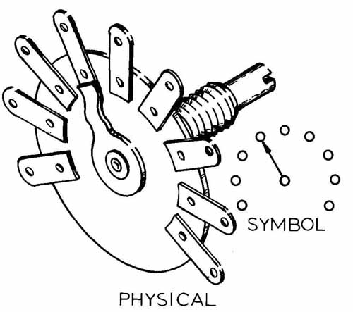
FIG. 1. A rotary switch and symbolic representation.
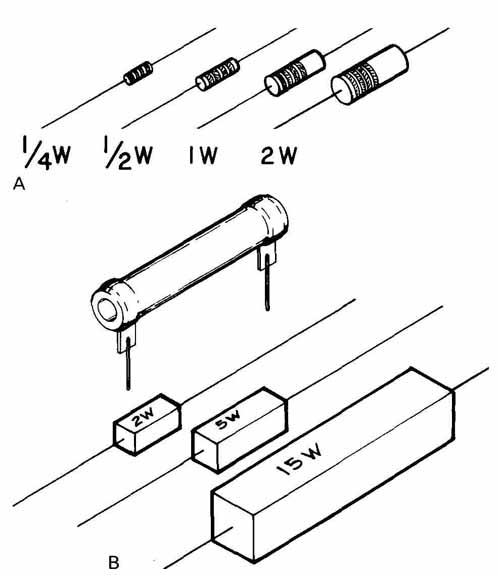
FIG. 2. Some typical resistor styles. A—Fixed carbon resistors sized
by wattage rating. B—Fixed, wirewound, high temperature resistors with
power ratings of 2 watts and above.
Resistors are referenced with the letter ‘ER.” Each component family will have a different letter to reference it, FIG. 3.
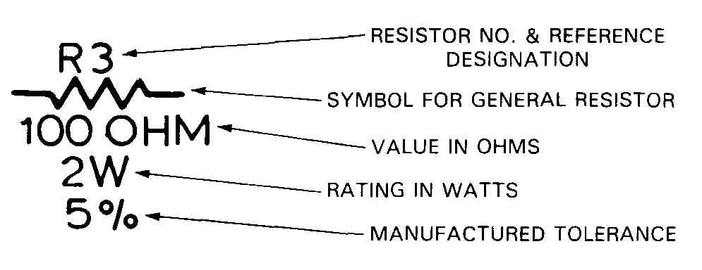
FIG. 3. A resistor symbol with complete information.
Resistors are valued in ohms. Their values can range from a fraction of an ohm to millions of ohms. Carbon resistors have a color code which is used to identify their values (see appendices for resistor color code).
Resistors are also rated in watts. The value in watts is the maximum power the resistor can safely handle. Carbon resistors normally range from 1/8 to 2 watts. Resistors above 2 watts are normally wirewound. The resistors will be larger as the voltage increases.
Resistors, like other components, cannot be made perfect. A tolerance must be given to allow for manufacturing errors. The tolerance will normally be a 1 to 10 percent variation from the stated value.
GENERAL RESISTOR
The general resistor is one in which there are no options. It serves the function of supplying a set and stated value. These resistors are called fixed resistors. Now let us look at some adjustable resistors.
RHEOSTAT
The rheostat is one of the variable resistors. It has two terminals. A typical use is to dim the light above your dining table. The symbol for a rheostat is shown in FIG. 4A. The moving arrow is called the wiper. The wiper moves across the resistor allowing you to adjust the amount of resistance in the circuit.
In FIG. 4B you see a dashed line between the two rheostat symbols. This line means ganged or mechanically coupled components. As the shaft adjustment of the component D moves, it adjusts both rheostats simultaneously. Note: In studying this new language, electronics, you will find other components with arrows. See if they are also variable.
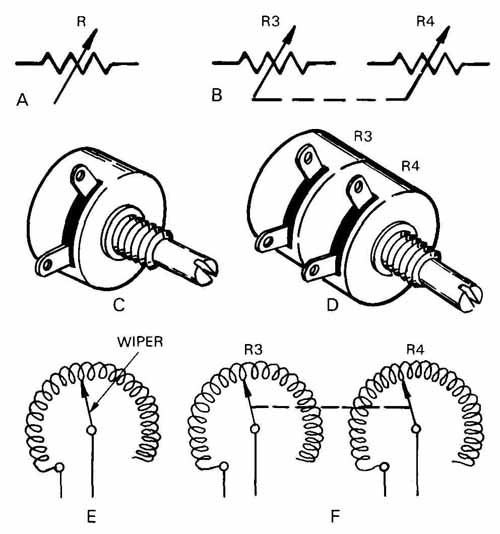
FIG. 4. A and B are two symbols used for rheostats. C and D are the physical
components. Sketches in E and F suggest how the resistance wire in a rheostat
is wound. Clockwise rotation of the wiper increases resistance.
POTENTIOMETER
The potentiometer is also a variable resistor. It is different from the rheostat in that it has three terminals. See FIG. 5. It may be used to balance a stereo speaker system.
The potentiometer may also be used as a rheostat. The wiper is tied to one end terminal thus making it a two terminal resistor like the rheostat, FIG. 6.
TAPPED RESISTOR
A tapped resistor is normally a wirewound type. See FIG. 7. It may have one or more terminals along its length. Tapped resistors are normally used for voltage divider applications.
RESISTOR PACKS
It is possible to purchase resistors packaged together in a single body. This package looks just like an integrated circuit chip, FIG. 8. The resistors in the package are normally of the same value.
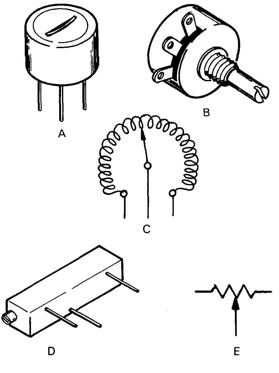
FIG. 5. Potentiometers have three terminals. Note the different physical
shapes of the components. This is based on how they will be used and
adjusted in the equipment. A— Rotary. B— Rotary. C — Symbol. D — Slide.
E— Schematic example.
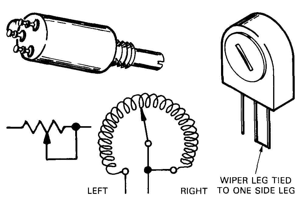
FIG. 6. Potentiometers with their wipers tied to one side perform as
rheostats.
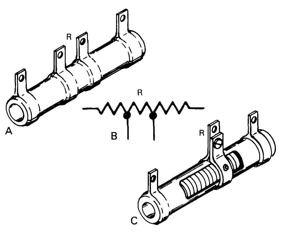
FIG. 7. A—A double-tapped resistor. B—The symbol for a double tapped
resistor. C—An adjustable tap resistor.
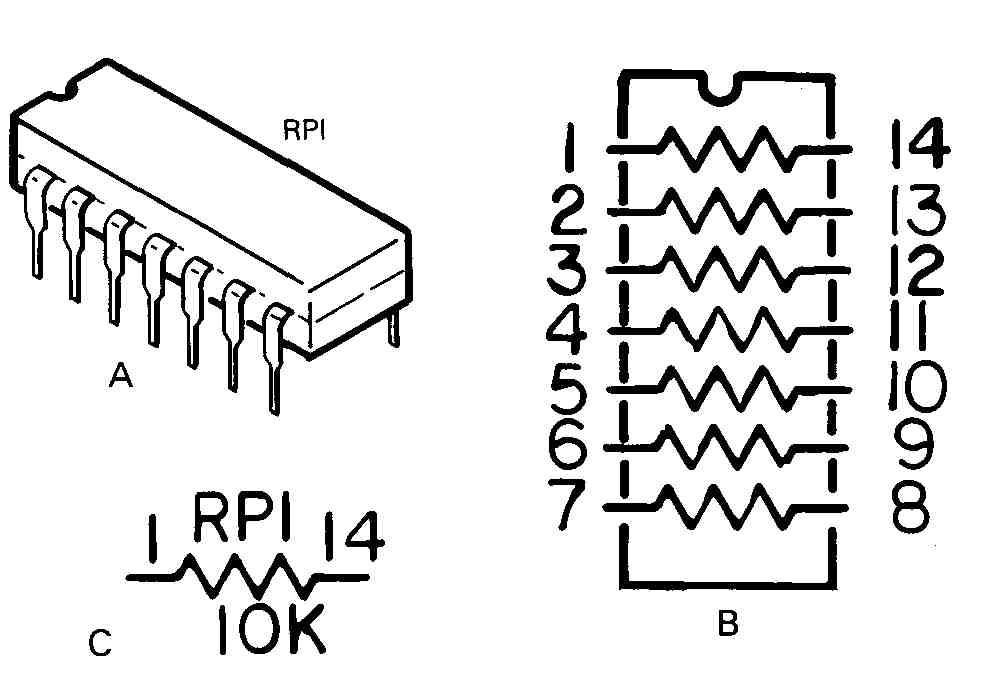
FIG. 8. A—One type of resistor package. B—A schematic of the package.
C—How to call out a resistor from resistor pack 1.
SEMICONDUCTORS
You will be studying a family of components called semiconductors. As components go, semiconductors are relatively new. These are the components that brought about the miniaturization of electronics components. Begin with the diode.
DIODE
The diode is a two-electrode semiconductor. It permits easy flow of electrons in only one direction. The flow is from the cathode to the anode, FIG. 9. It is necessary for the drafter to know the cathode and anode ends of the diode. This knowledge will help us show it correctly in the assembly of the circuit.
Note the 1N662 number shown in FIG. 9. This number is a catalog number. The engineer will call out this number to indicate the component wanted in the circuit.
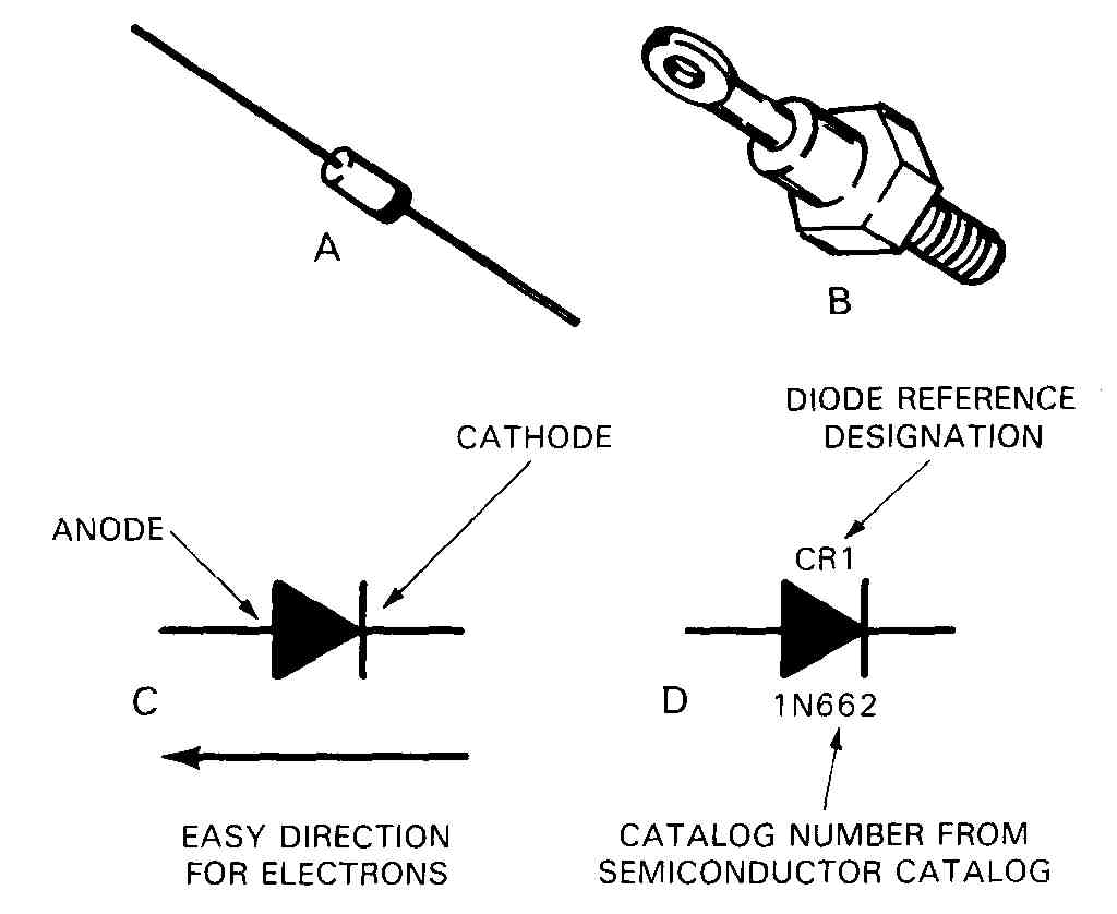
FIG. 9. General diode components end symbols. A and B—Typical component
shapes. C—Symbol with easy direction shown. D—A symbol with designation
(CR) and catalog number.
ZENER DIODE
The zener diode is a breakdown diode, FIG. 10. This means it draws more current as the rated voltage is reached. Zeners are used to regulate the voltage of a circuit. They may handle one to hundreds of volts. The zener diode symbol is different from that of a standard diode only in the way the cathode is shown.
BRIDGE RECTIFIER
The bridge rectifier is used to convert alternating current into direct
current, FIG. 11. Alternating current is electrical current that reverses
its direction of flow at regular intervals. Direct current is an electrical
current flowing in one direction only. A rectifier is used in our cars
to change the alternator output into direct current which is needed by
the battery and other electrical devices. The bridge rectifier may be
called a full-wave rectifier. it has four diodes that work together to
allow current in only one dir
ection.
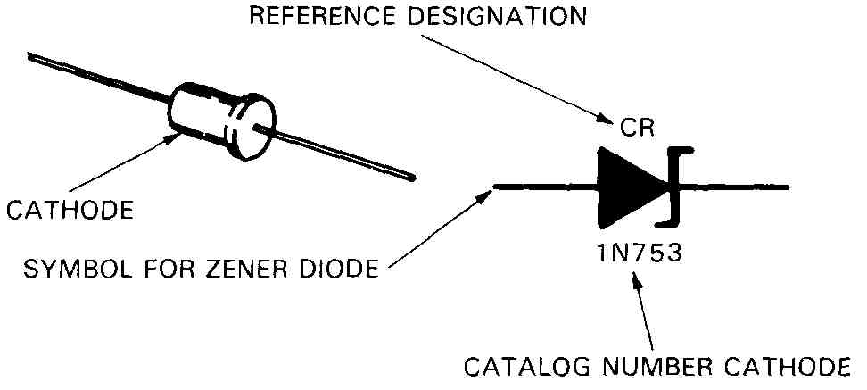
FIG. 10. A zener diode symbol.
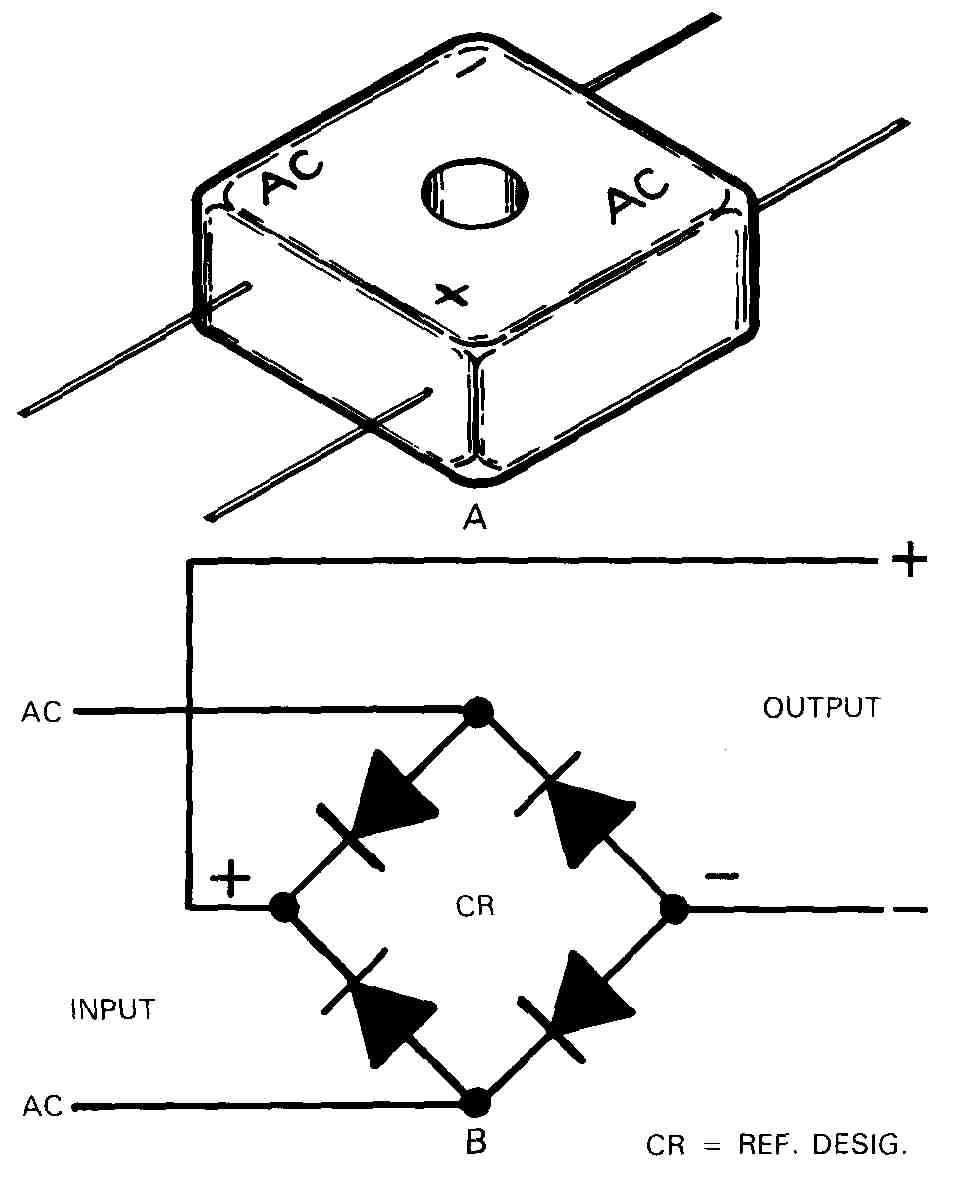
FIG. 11. A—A bridge rectifier. B—How the diode elements are linked
to perform the rectification.
TRANSISTOR
A transistor is an active semiconductor device used in solid state electronics, FIG. 12. This component along with the diode has all but eliminated the tube or vacuum tube. It normally has three electrodes: the emitter, base, and collector.
There are two basic types of transistors; the PNP and NPN type. In drawing the symbol the only noticeable difference is the direction of the arrow. The NPN arrow on the emitter points out of the envelope (the circle of the symbol), (A). The PNP has the arrow pointing into the base, (B). A way to remember the NPN type is: “NPN” reminds you that the arrow is “not pointing in.” There are other types of transistors, FIG. 1 3. These symbols are for units that perform specialized functions. The symbols will be used less often than for other transistors.
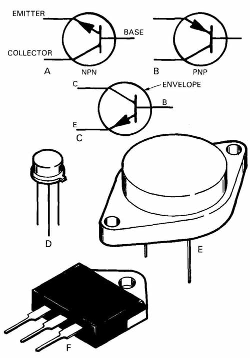
FIG. 12. A—An NPN transistor. B—A PNP transistor. C—A transistor symbol
with legs identified. D—A transistor case with the right leg identified
as the emitter leg. The little tongue is the indicator. E—A transistor
which has the body for a collector. E, F—Transistors are both made larger
so they can dissipate their heat. Sometimes they re mounted on other
metal shapes to help extract their heat.
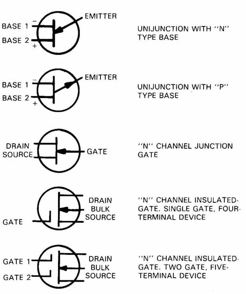
FIG. 13. The field effect transistors (FETs) shown in this example
have names by their symbols. This is just a guide explanation and is
not part of the symbol.
INTEGRATED CIRCUIT
An integrated circuit (IC) is an electronics device in which both active and passive components are contained in a single package, FIG. 14. These components are electrically interconnected during fabrication. The interconnected parts are then packaged in a protective coating. The package will have flat leads, A, C, or round leads, B, extending to the outside for electrical connections.
Passive components used in IC circuits are resistors, capacitors, and coils. These components are nonpowered and do not create or amplify energy. They rely on a signal to perform their function.
Active components used in IC circuits are transistors and diodes. These components are capable of controlling voltages or currents. They can produce energy or a switching action in the circuit. Their output is dependent on a source of power.
The miniaturization of circuits is one of the most important accomplishments in the field of electronics. The circuits are so small they must be constructed by technicians using microscopes. The circuits are made from very small pieces of silicon, commonly called chips.
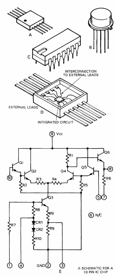
FIG. 14. A—A typical flat pack. B—A round metal can package. C—A dual
in-line package, the most commonly used style of integrated chip package.
D—A flat pack with the internal circuit exposed. E—An example of components
normally found inside the IC circuit.
HOW INTEGRATED CIRCUITS ARE MADE
Integrated circuits are created by masking, etching, and diffusion on a MONOLITHIC SUBSTRATE (large sheet foundation) of silicon. The mask is a set pattern used to control selective etching or impregnation of portions of a semiconductor material with impurity atoms. Etching is the removal, by chemicals, of unwanted material from a surface. Diffusion is the process of doping impurities into the silicon to form the desired junctions. From this complex explanation it is evident that a full study of the chip’s design and fabrication is beyond the scope of this text. However, we can take a simplified exploration of the chip to give you an appreciation of this device.
Integrated circuits are made on a thin slice of silicon with a diameter of one to two inches. A normal slice may contain 1 00 to 1000 circuits side by side. After processing, the circuits are separated to make an equal number of individual circuits called chips.
To create a chip, the typical processes are:
1. Get a wafer of P-type silicon as a substrate. The wafer will be thin slice of silicon doped or impregnated with positive impurities, FIG. 15.
2. Add a layer of N-type silicon about .20 microns thick. The layer is grown on the wafer. This N-type layer will become the collector for a transistor.
3. Add a thin coat of silicon dioxide. It is grown over the N-type material.
4. Mask the areas to be etched. The mask will establish the areas of acid resist. The wafer is then etched with an acid. The acid resist will cause the desired areas to be left, FIG. 1 6.
5. In the next step, the P-type material is diffused into all the areas not covered by silicon dioxide. Diffusion is the putting upon and into a base a P or N-type material, FIG. 1 7.
6. During the diffusion process, a new layer of silicon dioxide forms over the P-type areas and also on the top of the island.
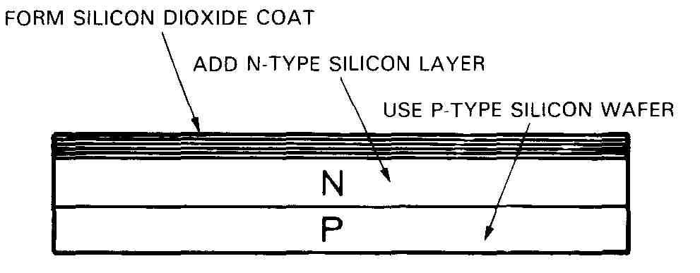
FIG. 15. The first three steps in IC construction.
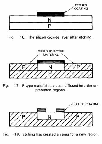
FIG. 16. The silicon dioxide layer after etching.
FIG. 17. P-type material has been diffused into the unprotected regions.
FIG. 18. Etching has created an area for a new region.
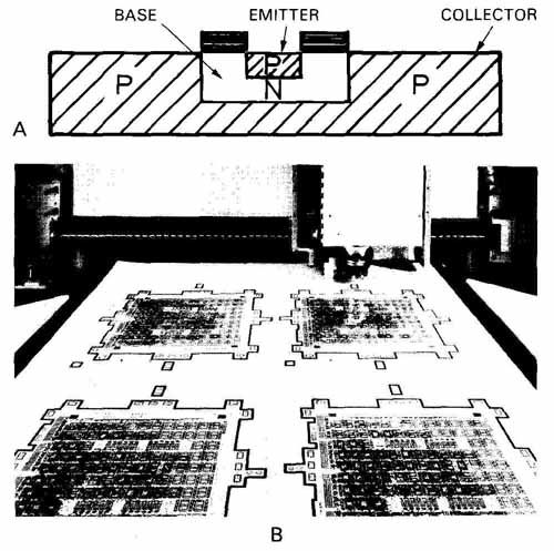
FIG. 19. A—The steps have shown how a transistor is created in an IC
circuit. Other components are created by these same techniques. B—A photo-plotter
creates integrated circuit artwork faster than by hand. (Gerber Scientific,
Inc.)
7. Using masking again we will control the etching away of the N-type island to create a new region, FIG. 18.
8. The wafer is exposed to another P-type diffusant and an area is created for the transistor’s emitter region, FIG. 19. Resistors, diodes, and capacitors may also be created between these regions.
9. After the circuit is completed, a thin coating of aluminum is vacuum-deposited over the en tire circuit. The aluminum is then etched to form patterns between the resistors, diodes, and transistors. The aluminum will also create pads for securing wires going to the external connections.
10. The wafer is then cut into separate circuits. This is a very simplified look at IC fabrication. There are also other methods and techniques for IC manufacturing. Scientists are now working on a chip created from grown protein. Advances are happening daily.
Advantages of IC circuits are their size, weight, cost, and reliability. The size of an IC is an advantage over the equivalent number of individual components. Size gives it a tremendous weight advantage. The cost of complete IC circuits are very often comparable to that of individual transistors. The IC has great reliability. It is 100 times more reliable than a single transistor. With all these advantages there are still some disadvantages.
Disadvantages are: It is difficult to create coils and capacitors in the IC package. They must work at low operating voltages and current ratings. The miniature diodes and transistors are delicate and cannot tolerate rough handling or excessive heat. The disadvantages are minor and insignificant compared to the advantages.
Some application for IC circuits are digital watches, pocket calculators, electronic games, stereo equipment, computers, and many other devices. The size and cost make IC circuits desirable for these applications.
CAPACITORS AND AC/DC COMPONENTS
A capacitor is a device consisting essentially of two conducting surfaces separated by an insulating material. The insulating material can be paper, mica, glass, plastic films, oil, or air. A capacitor stores energy, blocks the flow of direct current, and allows. the flow of alternating current.
GENERAL CAPACITOR
Like the general resistor, the general capacitor has one fixed and set value. This value is established by the spacing, FIG. 20, and/or the size of the plates.
VARIABLE CAPACITOR
Variable capacitors can be adjusted by changing the useful area of the plates or the distance between them, FIG. 21.
POLARIZED CAPACITOR
Polarized capacitors can be put in the circuit in only one direction. The symbol should be placed to the plus polarity. The plus side will be the straight side of the symbol, FIG. 22.
Information for the capacitor should be written as shown in FIG. 23.
SPACING WITH AN INSULATING MATERIAL OR AIR
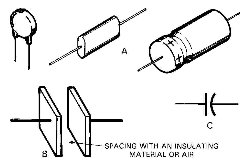
FIG. 20. A—Three of the many styles for common capacitors. B—The basic
structure of a capacitor. C—A general capacitor symbol. Note now the
symbol depicts the basic function.
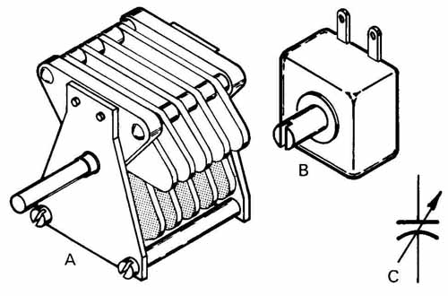
FIG. 21. A, B—Two types of variable capacitors. C— The symbol for a
variable capacitor. Note the arrow for variable.
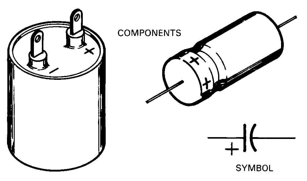
FIG. 22. A polarized (electrolytic) capacitor with its symbol. The
plus end is indicated on the physical component. In order to buy a general
capacitor you must tell the vendor three things: the value in farads,
the voltage rating, and the tolerance.
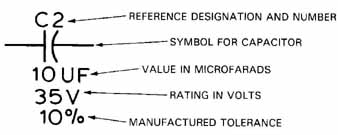
FIG. 23. A capacitor symbol with complete information.
COIL, CHOKE, OR INDUCTOR
The coil, choke, or inductor is a device made up of a coil of insulated wire around an iron, ceramic, or air core. See FIG. 24. It resists the changing of alternating current and its passage, but gives little opposition to the flow of direct current.
Coils are valued in henries, a unit of inductance. Resistance in ohms, and current-carrying capacity in amperes may also be listed, FIG. 25.
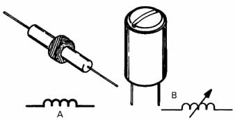
FIG. 24. A—A general coil and symbol. B—A variable coil and symbol.
SOLENOID
A solenoid is an electromagnetic device having an energizable coil and a magnetic core, FIG. 26. This core will move when the coil is energized. It performs mechanical functions. On our cars, it is used to engage the starter bendix gear when it is energized by turning the key to start the car.
Solenoids can be shown symbolically three ways, FIG. 27.
RELAY
A relay is an electromechanical device used to open and/or close contacts or switches as they are sometimes called. See FIG. 28. The part to operate the contacts is an electromagnet. It is a coil of wire around a soft iron core. The electromagnet moves a lever that opens or closes the contacts. Relays are used to start and stop many mechanical devices.
Relay symbols are shown differently from one company to another. They all describe the same device with some symbol variations, FIG. 29.
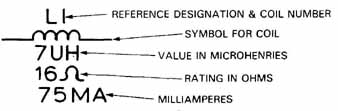
FIG. 25. A coil symbol with information.
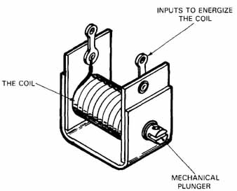
FIG. 26. A general solenoid. Solenoids use the same reference letter
as the coil: “L.”
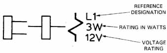
FIG. 27. Symbols commonly used for the solenoid.
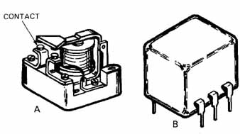
FIG. 28. A—An open relay showing contacts. B—An en capsulated relay
used on printed circuit boards.
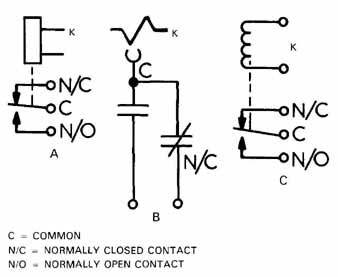
FIG. 29. The different ways to show a relay coil and contacts.
TRANSFORMER
The transformer is another electromagnetic device, FIG. 30. By induction, it changes primary voltage and current values to different values on the secondary. The frequency remains the same.
A transformer has two coils or a tapped coil. One coil will be the primary section, the other the secondary. They can step voltage up or down.
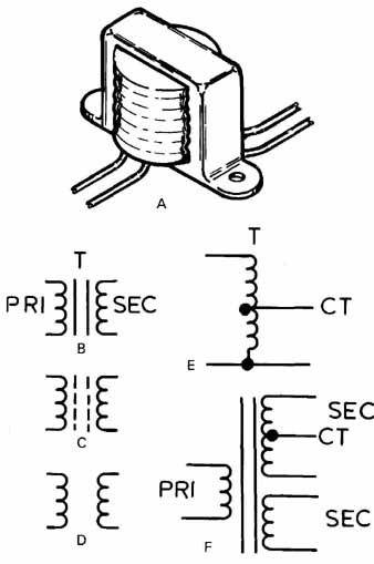
FIG. 30. A—A typical transformer. B—An iron core transformer symbol.
C—A ceramic core symbol. D—An air core symbol. E—An auto transformer
(single winding with a tap). F—A two secondary transformer with one being
center tapped.
The transformers we see on the utility poles in older neighborhoods are the stepdown type. They step the voltage down to a level we can use in our homes. Most transformers used in electronics are also the stepdown type. They take the incoming 1 20 volts down to levels used by the electronics equipment.
SWITCH
The switch a is mechanical or electrical device that opens or closes a circuit. Switching may also be called making or breaking the circuit. There are many different types of switches. FIG. 31 shows a rotary switch. Other switch types are toggle, sliding, rocker, and precision, FIG. 32.
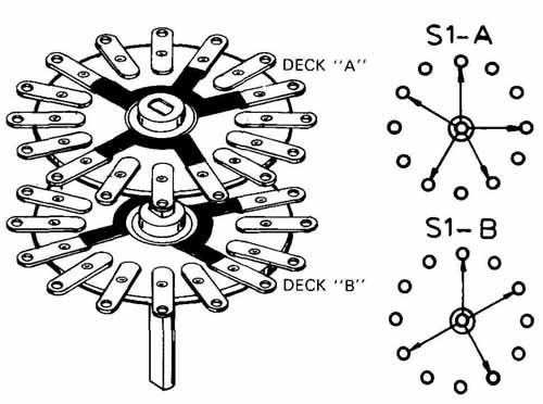
FIG. 31. A rotary switch with two decks. Each deck has multiple wipers
which are ganged or mechanically coupled to the rotating shaft.
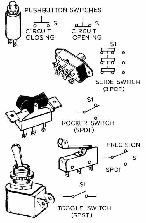
FIG. 32. The above switches show the major types used in industry and
their symbols.
The closing of a switch is called making the circuit. The opening of a switch is called breaking the circuit. Terms such as single pole, double throw, break before make, are used in switching. Fig. 33 shows some of these symbol forms.
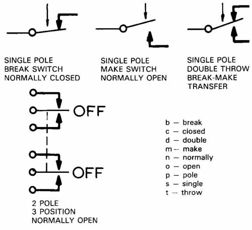
FIG. 33. Common switch terms.
Switches are referenced with the letter “s.” In order to purchase a switch we must indicate switch type, voltage, and amps. The switch information is presented in FIG. 34. The switch symbol should be drawn with the switch in its normal position. In the example, FIG. 34, the switch is a normally open type.
BATTERY
A battery is a direct current source made up of one or more cells. Refer to FIG. 35. These cells will convert chemical energy into electrical energy. The batteries contain the power supply for much of our portable electronics equipment. Calculators, transistor radios, and flashlights are some of the battery-operated devices you have used. Batteries are rated in volts and amps.
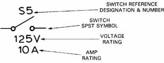
FIG. 34. A switch symbol with necessary information.
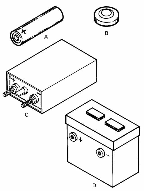
FIG. 35. A, B, C—Single cell batteries. D—A multicell battery.
Battery symbols are completed with the information shown in FIG. 36. The long line on the symbol indicates the positive side but the “+“ will normally be added for further clarification.
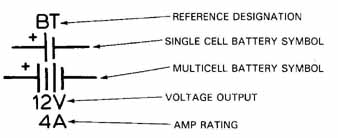
FIG. 36. Battery symbol with reference information.
ANTENNA
Antennas may also be referred to as aerials. Antennas are used to receive or transmit radiating waves. There are various types of antennas, so you will use different symbols to indicate the use of each, FIG. 37.
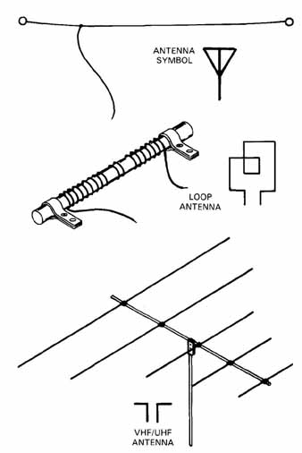
FIG. 37. Antenna types and associated symbols.
FUSE
Protective devices are used to safeguard electronics equipment. Some of these are fuses. A fuse usually consists of a short piece of wire or metal which separates when the current exceeds its pre set limits, FIG. 38. Fuses are rated in amps. Enough current causes the heat in the circuit that will burn out or melt the fuse wire. People commonly call this a blown fuse. If it were not for the fuses in a circuit, electronics equipment would be damaged and cause a far greater repair cost than replacing a fuse.
CIRCUIT BREAKER
A circuit breaker is another component used to protect electrical equipment, FIG. 39. Unlike the fuse, a circuit breaker will open an overloaded circuit without damaging itself. The circuit heat will cause it to open. Then as soon as the temperature is back to a normal operating range the circuit may be reclosed. Circuit breakers protect our homes. Most circuit breakers work by being thermally overloaded, but some use magnetic overload.
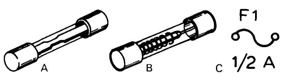
FIG. 38. A—General type fuse. B—Slow blow fuse. C—A fuse symbol representing
a 1/2 amp fuse.
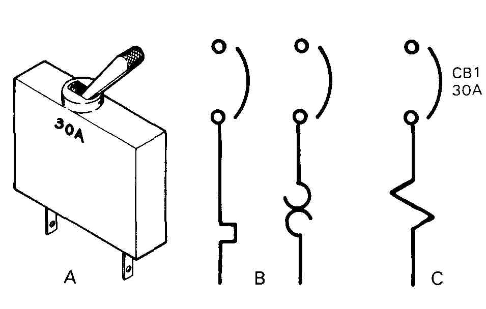
FIG. 39. A—Typical manually-operated circuit breaker. B—Thermal-overload
symbol for circuit breaker. C— Magnetic-overload symbol with reference
designation and amp rating.
CRYSTAL
A crystal is a thin slab of quartz, FIG. 40. It is built with a preset thickness so it will vibrate at a specific frequency when energized. It is used as a frequency control element in radio frequency oscillators. The channels of a citizens band radio are controlled by crystals.
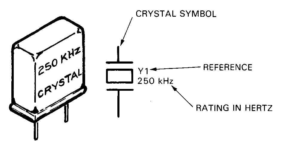
FIG. 40. A crystal and symbol with designation. This is a 250 kilohertz
crystal. Hertz (Hz) means frequency or cycles per second. This crystal
cycles 250,000 times per second.
OSCILLATOR
Oscillators generate alternating current. In radio frequencies, the alternating current may range from thousands to millions of cycles per second. An oscillator is the starting point for radio transmission. One style of oscillator is shown in FIG. 41.
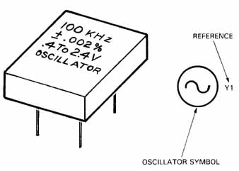
FIG. 41. An oscillator and symbol.
FILTER
A filter is a component designed to separate wanted signals from unwanted signals or frequencies. The filters are used to suppress certain bands of frequencies while passing others easily. Three categories of filters are: high-pass, low-pass, and band-pass. High-pass will allow only high frequency passage. Low-pass will allow low frequencies passage. Band-pass will allow a range of frequencies, cutting out those in the high and low ends.
Filters come in many body types. See one body type in FIG. 42.
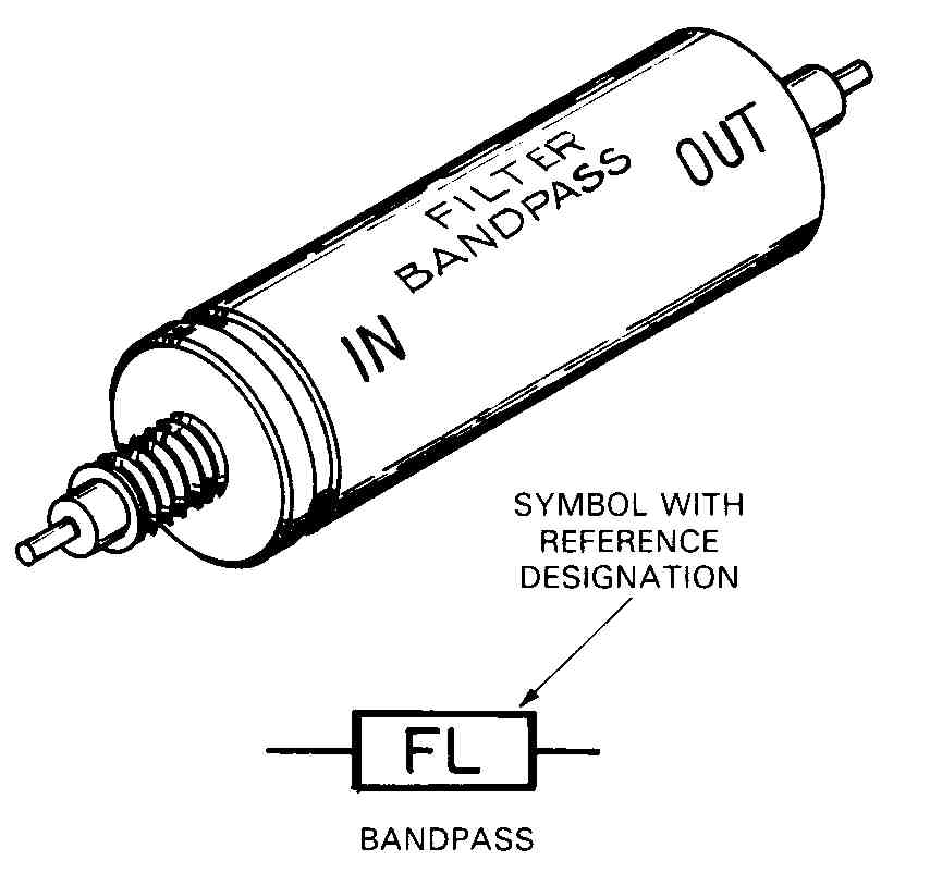
FIG. 42. A filter and symbol.
TUBE
Although tubes are being replaced by semiconductors, some are still in use. Tubes control electron flow much the way diodes and transistors do. They can amplify as transistors do and rectify as a diode does. FIG. 43 shows elements of tube symbols. Using these elements, you can create complete device symbols, FIG. 44. Tubes are much larger than their semiconductor counterparts.
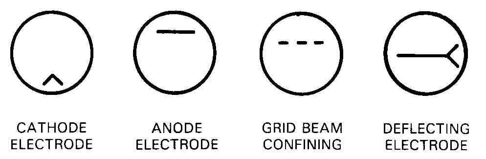
FIG. 43. Electron tube parts in symbolic representation.
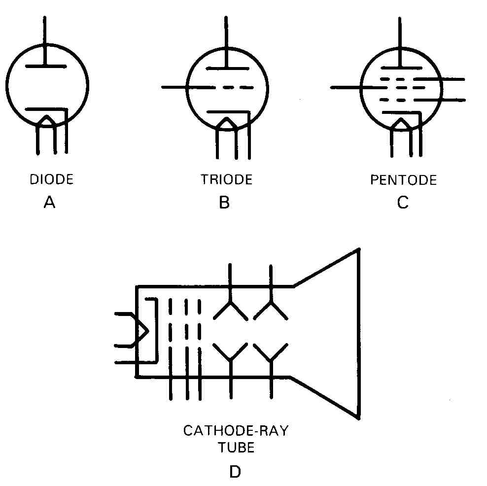
FIG. 44. A—The simplest type tube is a rectifier. B—Triode with heated
cathode. C—A five element tube with three grids. D—A cathode-ray tube
symbolically shown.
They create more heat during operation. This temperature requires a larger component so the heat can be dissipated. Most tubes are connected into the circuit by plugging into tube sockets, FIG. 45. This allows them to be replaced and checked easily.
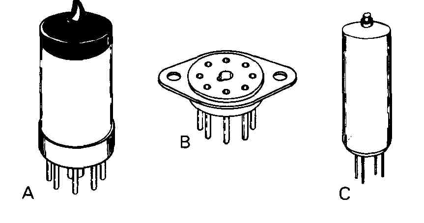
FIG. 45. A—A telephone tube. B—A keyed socket. Note: The center guide
pin will allow the symmetrical connection to fit in only one position.
C—Rectifier.
CONNECTOR
A connector is any device on the end of a wire or cable to allow equipment to be connected to or disconnected from other equipment.
There are many types of connectors, but we use only a few symbols. See FIG. 46.
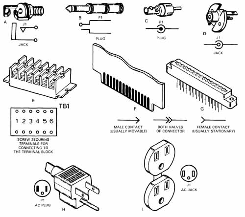
FIG. 46. A, B—Switchboard connector. C, D—Phono connector. E—A terminal
block. F, G—Printed circuit board connector. H, I—Power supply connectors.
CABLE, CONDUCTOR, OR WIRE
Cable may be referred to as conductor or wire. It comes in different styles for specific purposes. Types of cables and their symbols are shown in FIG. 47.
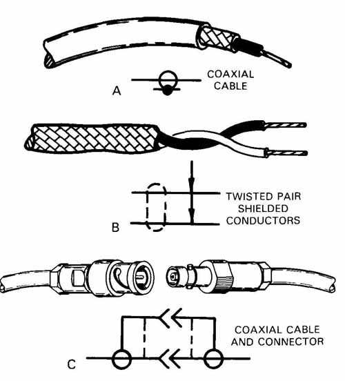
FIG. 47. A—A coaxial cable with symbol. B—A twisted pair with a shield.
C—Coaxial plugs and cable.
INPUT AND OUTPUT DEVICES
Electronics systems require an input and an output in order to complete a function. The inputs may be microphones or recording heads. Outputs may be speakers or headphones, FIG. 48. Each component is shown with symbol and reference designation.
A microphone is an electroacoustic transducer, which responds to sound waves and delivers essentially equivalent electric waves to the amplifier. The speaker radiates acoustic power into the air with essentially the same waveform as that of the electrical input.
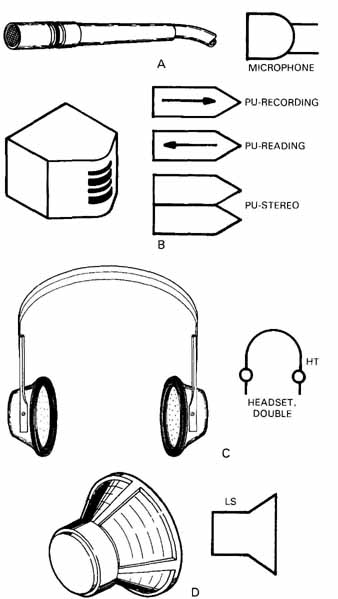
FIG. 48. A—A general microphone. B—Read, record, and stereo magnetic
tape heads. C—Headphones. D—A speaker or loudspeaker. Each component
is shown with symbol and reference designation.
INDICATING, PILOT, AND SIGNALING LIGHTS
Lights perform different functions in electronics. They can be used as indicating lights. See FIG. 49. These lights will normally indicate such things as “power is on,” “temperature is too high,” or there is some information needing to be indicated.
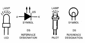
FIG. 49. Indicating lamps and accompanying symbols. Note LED lamp.
ILLUMINATING LIGHT
Area lights are lights which are used to light our homes and yards, FIG. 50. Lights which light up control panels so that meters and gages can be read are called illuminating lights. They are the same as area lights but normally smaller in wattage.
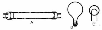
FIG. 50. Typical lamps. A—A fluorescent. B—An in candescent. C—The appropriate
symbol. “DS” is the reference letter.
METER
Meters are used to show levels of current, frequency, speed, temperature, time, and other information. Examples of meters and their symbols are shown in FIG. 51.
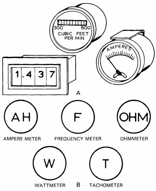
FIG. 51. A —Three types of meter faces. B— Symbols for standard meters.
ROTATING MACHINERY
Many of our electronics drawings will involve motors, generators, and their controlling circuits.
MOTOR
A motor is a machine that converts electrical energy into mechanical energy. It normally creates rotating power by turning a power shaft. Motors are used to drive sound equipment: phonographs, magnetic tape players, cooling fans, and many other applications, FIG. 52.
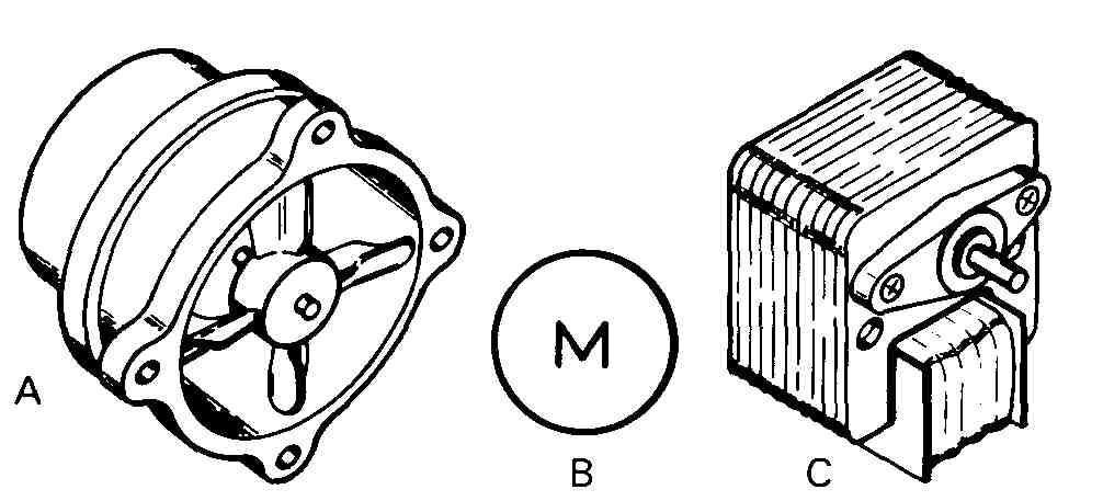
FIG. 52. A—Electric motor. B—Electric motor symbol and reference letter.
C—Motor which can work as a combination motor-generator.
GENERATOR
A generator is a rotating machine which converts mechanical energy into electrical energy, FIG. 53. It can be used also to convert direct current voltage into alternating current of the desired frequency and amplitude.
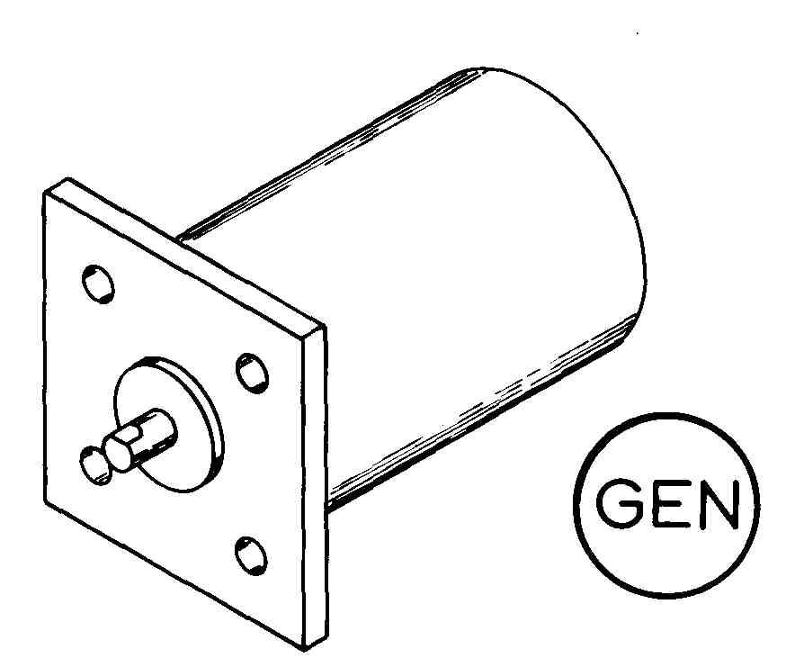
FIG. 53. A generator and symbol with reference designation.
CIRCUIT RETURNS
There are three symbols used for circuit returns. They are earth ground, chassis ground, and common ground symbols. Earth ground, FIG. 54A, is used to return the circuit directly to earth. AC circuits will use the earth ground symbol. Chassis grounds, FIG. 54B, are used to indicate circuits which return to the equipment’s frame or chassis. The auto is a good example of a chassis ground unit. Common ground, FIG. 54C and D are used to show returns which have the same potential. This potential does not have to be zero. A common ground is sometimes called an airline.
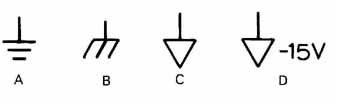
FIG. 54. A—Earth ground symbol. B—Chassis ground symbol. C—Common ground
symbol. D—Common ground symbol with a modifier, which will make it common
to other — 1 5V sources of the drawing.
COMPONENT VALUES
There are preferred ways to write quantities in units such as ohms, volts, or henries. The values should be short and readable. Component values are expressed as shown in FIG. 55.
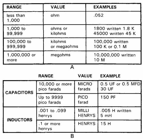
FIG. 55. A—How to write resistor values. Symbol K will be hand-lettered
in capitals. B—How to write capacitor and inductor values.
STANDARDS
All of the symbols and reference designations in this Section comply with a standard. The two major standards are:
USAS Y32.16 Reference Designations for Electrical and Electronic parts and equipment.
USAS Y32.2 Graphic Symbols for Electronics and Electrical Diagrams.
Military standards are considered when military or government contracts are involved.
SYMBOL MODIFIERS
There are many things we can do to a basic symbol to change its meaning. Modifiers are used to change a component’s meaning. You have seen some of the modifiers used earlier in this Section. Note some additional modifiers and their uses in FIG. 56.
Polarity. Used to indicate which direction a device is installed in the circuit.
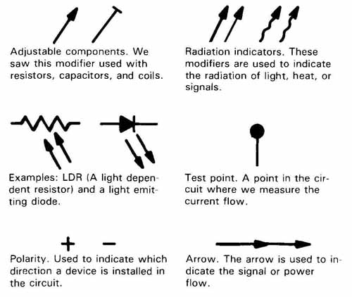
FIG. 56. Modifiers used to add meaning to basic symbols.
REVIEW QUESTIONS
1. What function does a resistor perform?
2. What regulates the amount of resistance?
3. What phrase reminds you of the NPN type of transistor?
4. Using the resistor color code, (appendix), state the value for the following resistors.
a. brown black brown silver
b. orange green orange gold
c. brown green orange silver
d. orange black green gold
5. Provide the colors for the following:
a. 270 ± 5%
b. 2400 ± 10%
c. 4.7K ± 10%
d. 5.6K ± 5%
e. .18M ± 5%
f. 1.1M ± 5%
6. Explain how a rheostat works.
7. A capacitor blocks _________ (AC, DC).
8. What information must be given when purchasing a capacitor?
9. What does a coil do?
10. How many symbols are used to show solenoids?
11. What are the two sections of the transformer?
12. Relays perform what functions?
13. What does mean when placed between two adjustable symbols?
14. What type of current source does a battery provide?
15. What is the main difference between a fuse and a circuit breaker?
16. What are two ends of a diode?
17. How are zener diodes used?
18. Tubes have been replaced by what components?
19. What does it mean to you when it is stated— a connector is Keyed?
20. What does it mean to correctly reference a resistor? List about three ideas.
PROBLEMS
PROB. 1. Draw a resistor symbol and provide all identifying information.
PROB. 2. Practice drawing a transformer symbol. Add a center tap symbol. Provide all needed information.
PROB. 3. Using your symbol template, create the following components: Label each with the appropriate reference designation.
1. Transistor (PNP).
2. Loop antenna.
3. Diode (Zener).
4. Potentiometer used as rheostat.
5. Transformer (iron core)
6. Tapped resistor.
7. Transistor unijunction.
8. Fuse.
9. Chassis ground.
10. Coaxial cable.
11. Battery multi-cell.
12. Circuit Breaker.
13. Inductor.
14. Capacitor (Variable).
15. Switch (mechanically coupled) (rotary).
16. Speaker.
17. Microphone.
18. Pickup head.
19. Motor.
20. Transistor (NPN).