AMAZON multi-meters discounts AMAZON oscilloscope discounts
After studying this Section you will be able to:
- Select wiring methods.
- Create a wire list.
- Draft a Point-to-Point diagram.
- Draft a pictorial Point-to-Point diagram.
- Draw a highway diagram.
- Draw an interconnection diagram.
- Draw a cable assembly.
- Make harness assembly drawings.
- Select wire termination methods.
The majority of electronic equipment needs some kind of wiring interconnections. Understanding how to document this wiring is important knowledge for the drafter. This Section will cover the basic methods used by the major companies.
WIRING METHODS
There are many ways to show factory workers, service personnel, and others in the engineering family how to wire electronics equipment. Normally the decision to choose one method over another is based on three different things:
1. Knowledge of the technician.
2. Quantity to be built.
3. Complexity of the equipment to be manufactured. Here are some of the ways drafters document wiring.
SCHEMATIC
The simplest method to get a wiring project built is to give a top qualified technician a schematic. The schematic will only supply the “from” and “to” in formation. This information will describe where the wire will be hooked (the from position) and where it is going (the to position), FIG. 1.
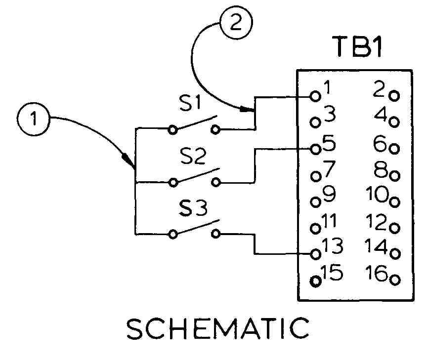
FIG. 1. A schematic being used to wire between components. Note 1: Technician
runs a wire connecting all switches. Note 2: Wire is run from S1 to TB1-1
(the terminal block).
From a schematic, a drafter can create a wire list or other wiring documents. The wiring list will save the technician time in reading the schematic.
The wire list is another elementary document. It will include the information from the schematic plus some additional information such as:
1. Color of wire.
2. Gage of wire.
3. Length of wire.
4. Entry in parts list.
5. Condition at terminals.
FIG. 2 shows how the wire list information is presented. To understand the wire list information, you need to be familiar with wires and their terminations.
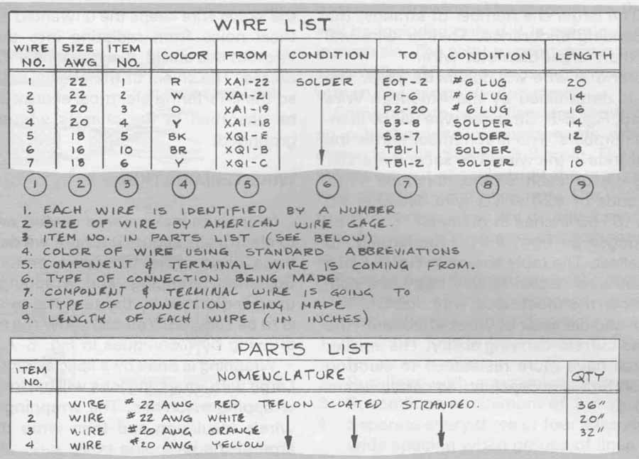
FIG. 2. Wire list and accompanying parts list. Note: Parts list numbers
are used in column 3 of the wire list.
WIRES OR CONDUCTORS
Conductors used in wiring electronics equipment are of three different types: solid, stranded, and flat ribbon, FIG. 3. Solid conductors have traditionally been used where they will not experience bending. They are less expensive than stranded wires, but have a more limited use. In electronics, solid wiring is used mainly for jumpers (bus wiring) and for a process of wire wrapping.
Stranded wire has superior handling and flexing qualities. This makes it the most universally used wire. Refer to FIG. 4. The endurance of the stranded wire is judged by the number of strands it contains. The larger the number of strands, the greater its bending endurance. Thinner wire will bend better than larger diameter wire.
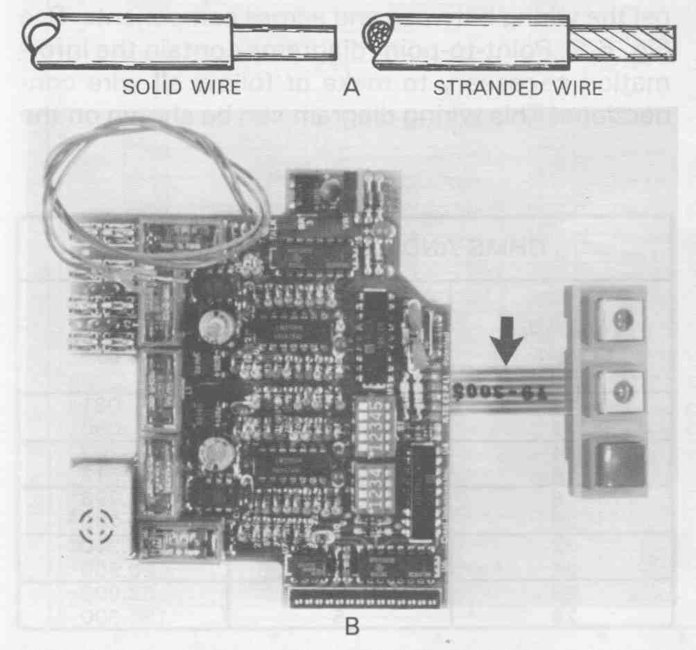
FIG. 3. A—An example of stranded and solid conductors. B—Stranded round
wire and flat ribbon cable. (See arrow.)
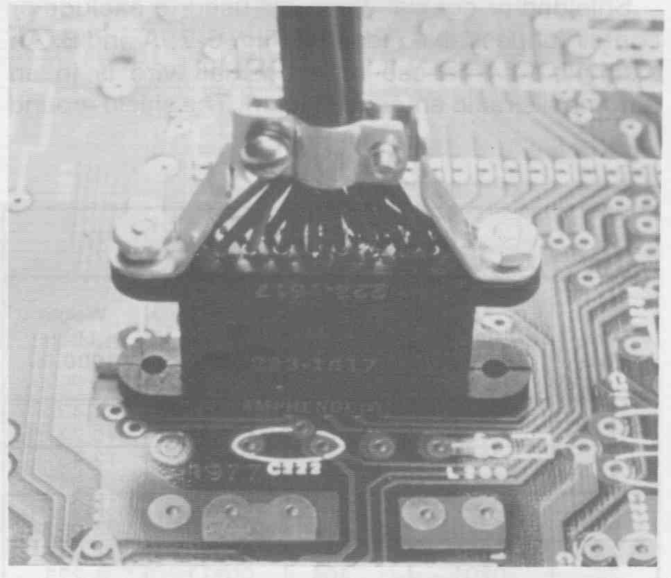
FIG. 4. A cable termination on a circuit board saves space on the board
edge. A flexible mounting and stranded wire help reduce stress on board
and on connector. (Amphenol Products)
The diameter of a wire will decide its gage. The wire’s gage is determined by the American Wire Gage Standard, FIG. 5. Stranded wire will be identified by two numbers. The first number states the number of strands in the wire. The second number states the gage of each strand. Example 7/26 means 7 strands of #26 AWG wire. Number 26 gage wire is .0159 inches in diameter, FIG. 5.
The wire gages go from #4/0—the largest, to #44, the smallest. The table shown in FIG. 5 has only given the even sizes. It also has been condensed to show the most used wire sizes.
Wire length and diameter of wires affect both the resistance and current-carrying ability. The smaller diameter wires have more resistance to electron flow, and therefore less capability to carry current loads, FIG. 6.
FIG. 6. Current ratings for wires. Military standards allow only 60% of these current values. (not shown)
BUS WIRE
Bus wire is bare wire (without insulation) normally used to make short terminal-to-terminal connections. It is solid wire, so it will be used where bending does not take place after installation. Where the bus wire requires insulation, a tube type insulation is slid over it. This tube insulation is called SPAGHETTI. The reason for using spaghetti is to avoid having to strip both ends of a short wire.
FIG. 5. The American Wire Gage table. (not shown)
SHIELDED AND COAXIAL CABLES
Shielded or coaxial wires are used to exclude or contain undesirable radiation, FIG. 7, A and B. An example for the use of a coaxial wire is in an automobile radio antenna system. The shield around the signal wire keeps the unwanted engine and electrical noise from radiating into the signal wire. Without this shield, we would hear many interfering noises. The shield of the coaxial cable is grounded so the interfering electrical energy or radiation will be absorbed in the chassis where the shield is grounded.
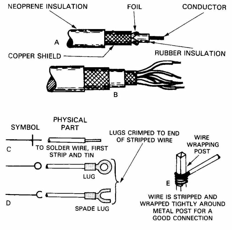
FIG. 7. A—Coaxial cable. B—Multi-conductor shielded cable. C, D, E—The
three ways wires are terminated. Letter E shows wire wrapping post and
wrapped wire.
WIRE TERMINATION
In order to make a wire useful, we must be able to electrically secure it where we desire. There are three basic ways to secure or terminate wires:
Soldering, crimping, and wrapping. The method used is dictated by the terminal to which the wire is to be secured. You can show the method on your drawing by techniques in FIG. 7, C, D, and E.
Wrapping is done by a special wire-wrapping tool. Large wire-wrapping jobs will be done by automatic wrapping machines. The wrapping tools strip the wire’s insulation and then wrap the wire tightly around the wrapping post.
Wire-wrapping has an economical advantage over soldering and crimp terminations. Wrapping can be set up much easier for automated machines.
Wire used for wrapping terminations is solid wire. The gages for this wiring method range from #20 AWG to #32 AWG.
POINT-TO-POINT WIRING DIAGRAMS
The purpose of a point-to-point diagram is to show the engineering, manufacturing, and service personnel the wiring between and across components. See FIG. 8. Point-to-point diagrams contain the information necessary to make or follow all wire connections. This wiring diagram can be shown on the assembly drawing. The diagram on the assembly will be included only if it is practical, and if room is available. The point-to-point drawing will not have a parts list. All the necessary items will be called out on the assembly document.
Some point-to-point diagrams show wiring paths on a background of components which are not drawn to scale. See FIG. 8 again. The components are drawn out of scale to fit the requirements of a very complex wiring diagram. The wiring is easier to follow when wires are on equal spacing. A second drawing often shows the components drawn to the true scale.
Point-to-point diagrams show the general physical arrangement of the component parts, FIG. 9. General rules for wiring diagrams are:
1. Minimize jogs in lines. Refer to FIG. 9 again for an example.
2. Run lines with a minimum of crosses.
3. Space lines a minimum of 3/8 in. apart.
4. Separate every three or four lines with an extra wide spacing when groups of lines run parallel to each other. This helps the reader’s eye follow the individual lines.
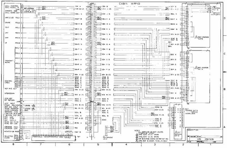
FIG. 8. A complex industrial point-to-point drawing shows assembly
specifications.
5. Label components on the right side. This will help the reader when searching over a large drawing to find a specific component.
6. Letter the components with larger bold letters. Use smaller lettering for internal terminals.
7. Number components from the upper left hand corner. Make the diagram read as a book with the highest component number being in the bottom right corner.
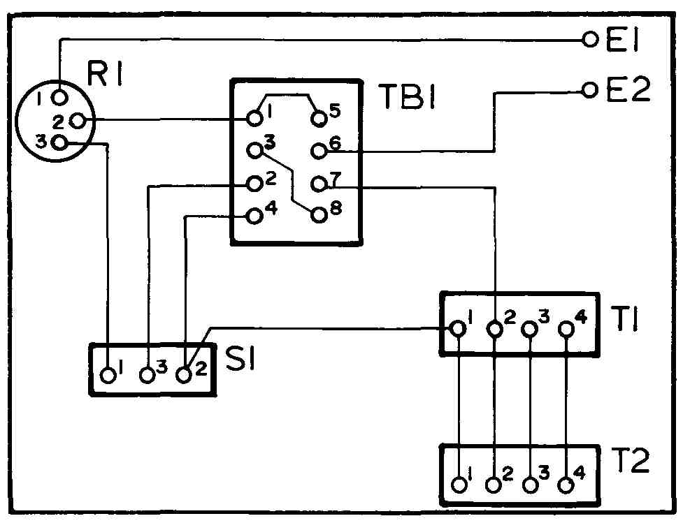
FIG. 9. A correctly drawn point-to-point wiring diagram. Note the mis-numbering
of TB1 and S1 to keep from crossing and jogging. This is a good practice.
PICTORIAL POINT-TO-POINT DRAWING
Occasionally when there is a simple point-to-point drawing to be made, it can often be drawn as a pictorial. FIG. 10 is a good example of a pictorial point-to-point drawing. However, pictorials should only be attempted when there are only a small number of wires and simple chassis layouts.
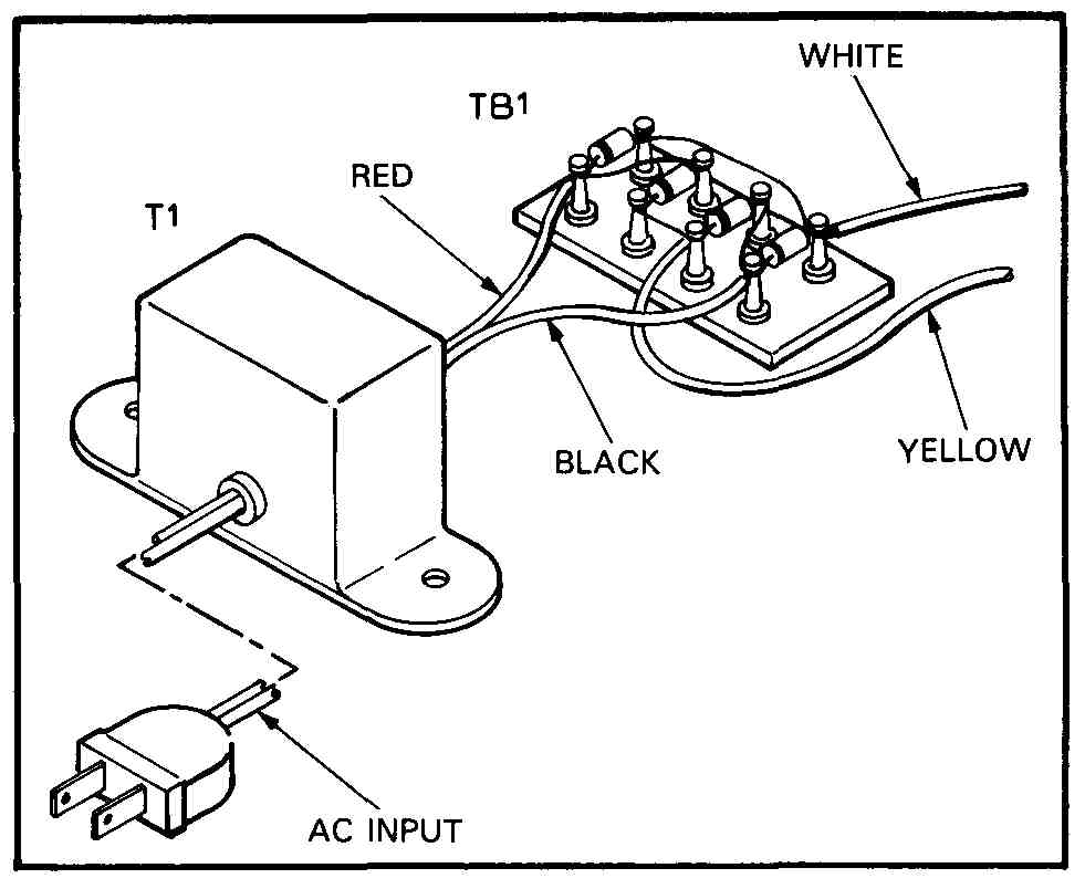
FIG. 10. A typical pictorial point-to-point.
HIGHWAY WIRING DIAGRAMS
The highway wiring diagram groups the wires together into major paths called highways, FIG. 11. The technique allows you to put many wires on a drawing because this organized method saves room. The drawing shows the physical arrangement of the component parts as we did in the point-to- point. It will be possible to tell each wire’s destinations, color, and gage by looking at either of its ends.
In FIG. 11 D we see a second method for showing highways. Note that some companies apply a number to each wire and then create a separate table. The wire number in the table will supply destination, color, and gage.
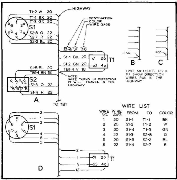
FIG. 11. A—Typical highway diagram. This method can handle many wires
in an organized manner. B, C—Two methods for routing individual wires
into the highway. They both show direction of travel. D—An alternate
method for highway diagrams. It uses a table to show the wiring information.
The table may be typed on the drawing, reducing drafting time. But it
is slower to read than in Part A because the reader goes between the
table and drawing.
BASELINE DIAGRAMS
Baseline diagrams are like highway diagrams in two ways. They both can handle many wires in an organized manner, and they bundle the wires together in one main line, FIG. 12. They also have a couple of differences. One is the placement of components. The highway diagram is very concerned with physical placement of the components. The baseline diagram just lines them up in a straight line.
Another difference is in the way the wires enter the main bundle. The highway diagrams shows which way the wire will be running in a bundle. The baseline just goes into the wire bundle at 90 degrees.
The method for drawing baseline diagrams is to:
1. Construct a light line across the middle of the paper.
2. Line up the component on either side of the line.
3. Take short lines from each component and run them into the center line at 90°.
4. Identify the wire destination and color.
5. Make the center line a dark bold line, FIG. 12.
Baseline drawings are used mostly for service manuals and maintenance books. They are especially good for this kind of information because they can neatly show many lines on a book size sheet of paper. These drawings will not normally be used for assembly work because the information is too limited.
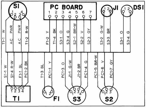
FIG. 12. A baseline diagram showing another method of controlling many
wires in an organized manner.
INTERCONNECTION DIAGRAMS
Interconnection diagrams show the wiring be tween different electronics units and between sub- assemblies, FIG. 13. This document is similar to the point-to-point wiring diagram. Each cable assembly and electronic unit will be called out and assigned a title and drawing number. Note the subassemblies are shown in phantom lines. Internal connections of electronic units are not shown.
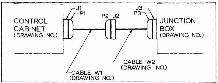
FIG. 13. A typical interconnection diagram. This is an assembly drawing
and will require a parts list. Subassemblies on an interconnection diagram
are shown in phantom lines.
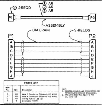
FIG. 14. A cable assembly and a schematic of its wires.
CABLE ASSEMBLY DRAWINGS
Cable drawings are assembly drawings, FIG. 14. They contain all necessary information to manufacture a finished cable. The drawing will include the following information:
1. A complete parts list.
2. A drawing showing all components.
3. Reference designations for each component.
4. A wiring diagram most often is part of the drawing. It will show the internal wires in the cable.
5. A general note section which will guide the assembler through the assembly.
WIRE (CABLE) HARNESS ASSEMBLY DRAWING
The wiring harness is the only wiring drawing drawn to exact scale, FIG. 15. It is drawn to scale because it is not just a drawing, but it is also a tool.
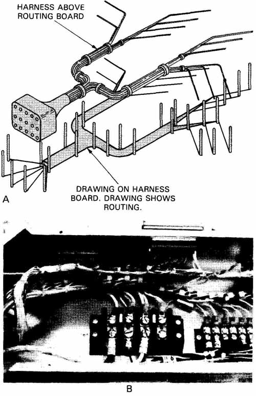
FIG. 15. A—Harness being removed from the harness routing board. B—Picture
of harness installed in equipment.
This tool will be used in manufacturing so that many identical parts can be created. Harness drawings will be supported by a wiring list and parts list. It is an assembly so it will need to be supplemented with all information needed by the assembler. The benefits of this drawing are:
1. It will support high volume manufacturing.
2. It will not require high priced technicians.
3. Quality control of the wiring is easier.
4. The assembly is less expensive to produce than many separate wires.
Before we can begin a harness drawing, we must know the exact placement of all the electrical components to be hooked up. The layout of the drawing and the routing of the harness will be decided by studying this arrangement, FIG. 16. Once we know where the harness will run, we can plan the layout on the drawing.
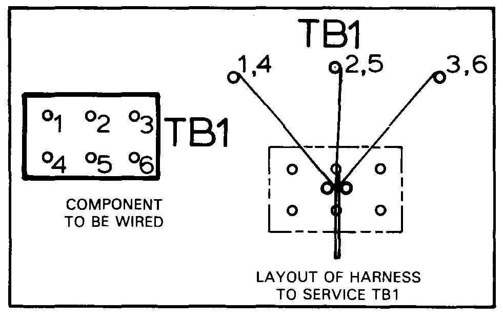
FIG. 16. Terminal block one needs to be wired. The right view shows
how the wiring will be routed to service TB1. Note: The wires
go beyond the position of TB1. This is to provide a service loop so the
wires can be easily hooked and unhooked.
Routing of the wires in a harness is accomplished by retaining them between HARNESS POSTS, FIG. 17. Harness posts will be driven into a routing board as the drawing directs. Harness posts will also be used as securing posts for each end of the wire. The wire will be wrapped around the starting post. Once secured, it will be run through the routing posts as described by the wire list. After routing, it will be secured around an ending post.
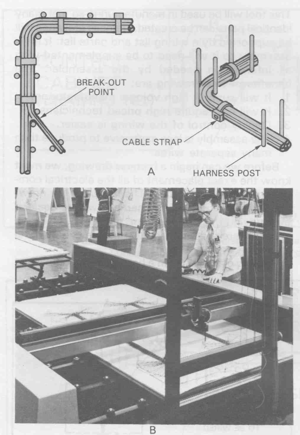
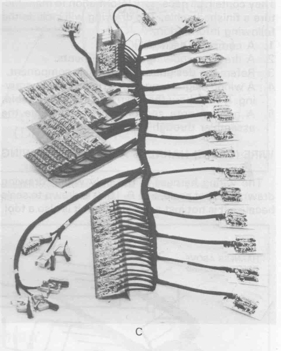
FIG. 17. A—Wiring being routed through harness posts. B—Picture of a
wiring harness being automatically routed. C—Example of a completed wiring
harness. (Amphenol North America Division, Bunker Ramo Corp.)
LACING or strapping of the harness will be done after all the wires are routed. See FIG. 18. Lacing or strapping is the bundling of the wires into a permanent unit. Once the wires have been permanently bundled, they can then be lifted up off the routing board. After a harness has been removed, another duplicate harness may be started.

FIG. 18. An example of lacing being applied around a wire bundle. See
FIG. 17 for an example of cable straps. Lacing and cable straps are applied
to keep the wire bundle in the desired shape.
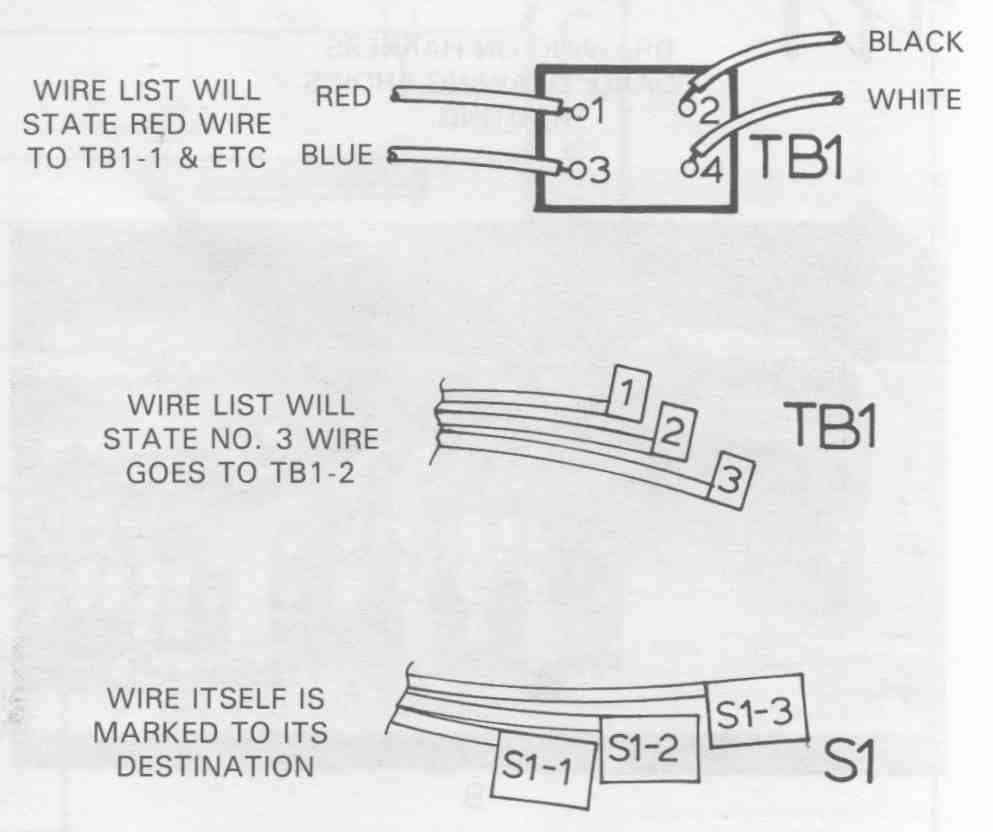
FIG. 19. Three ways to identify wires to aid in the harness installation.
After the harness has been manufactured, it will go to a higher assembly
level where it will be in stalled. In order to make the installation
easier, we identify each wire in the bundle. There are three methods
of identifying wires, FIG. 19. The three methods are: Color, number,
or destination. When using colors, each wire carrying a different electronic
signal will have a different color. Numbered wires will be numbered on
both ends with the same number tag. A wire identified by destination,
will have the exact place where it is to be terminated tagged right on
its ends. The destination method will eliminate the need for a wire list
during installation. Numbered and colored wires must have a wire list
with the harness in order to complete installation.
TYPICAL NOTES USED ON WIRING DIAGRAMS
Here are often-used notes for wiring diagrams:
1. This drawing used with— Assembly drawing
Schematic drawing
Wiring diagram
2. Wire lengths determined by prototype
3. Wire color coding per MIL-STD-681
4. Wiring must conform to ____________
5. Soldering will conform to ___________
6. Unless otherwise specified, all wires are ____
7. Lace harness at each breakout point and every ________ inch in between
8. Apply cable straps at each breakout point and every _____ inch in between
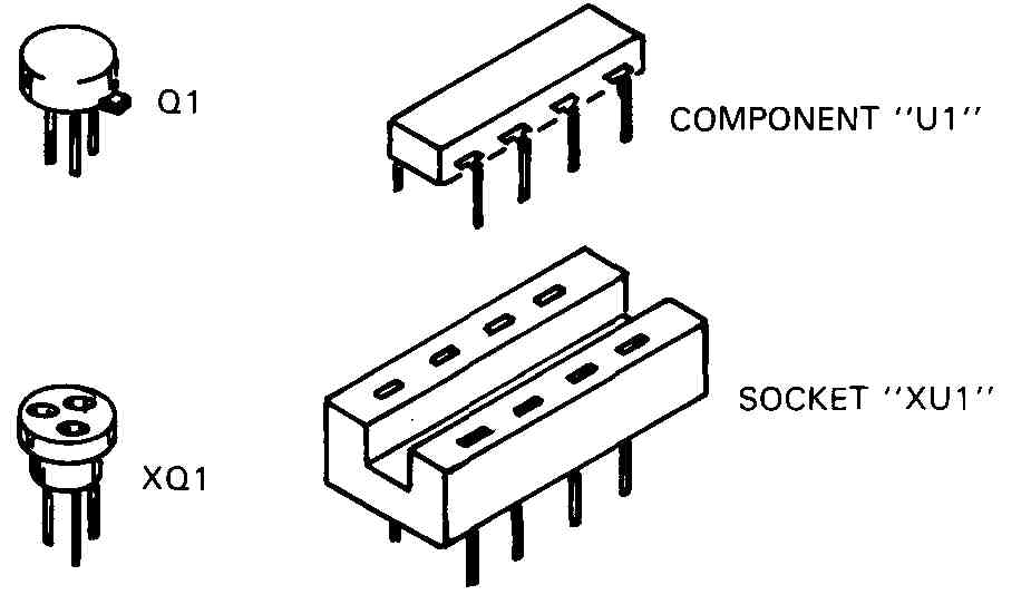
FIG. 20. Components and sockets and their reference designations.
REFERENCE DESIGNATIONS
Reference designations shall be identical to those on the schematic except for component sockets which are prefixed “X”. See FIG. 20.
COMPONENT REPRESENTATION
Component representation shall be just a physical outline suggestive of the component’s features, FIG. 21 . This is meant to be a simplified view as seen from the wiring side.
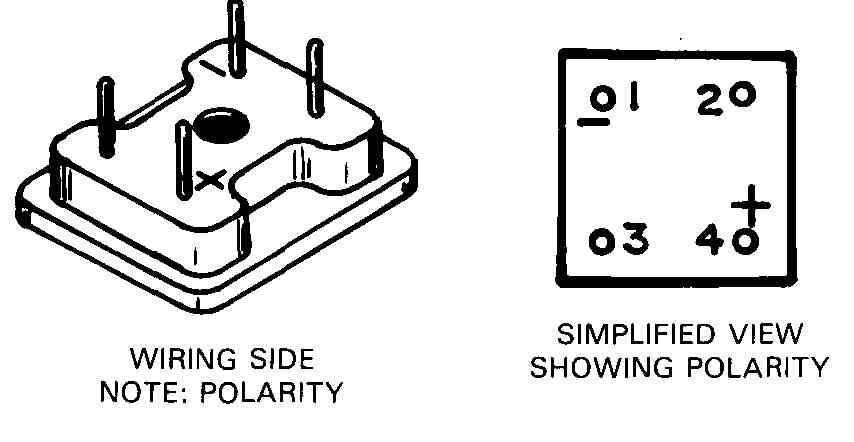
FIG. 21. The actual component, left, and its representation on the right.
Note: Pins have been assigned numbers. This helps the technician during
wire installation.
TERMINAL IDENTIFICATION
Each terminal must be identified. Most components and connectors are marked adequately, but if not: sufficient details must be supplied with a wiring diagram. Leads of components, such as transistors, diodes, electrolytic capacitors, batteries, and other devices shall have their terminals identified or polarity marked, as in FIG. 22.
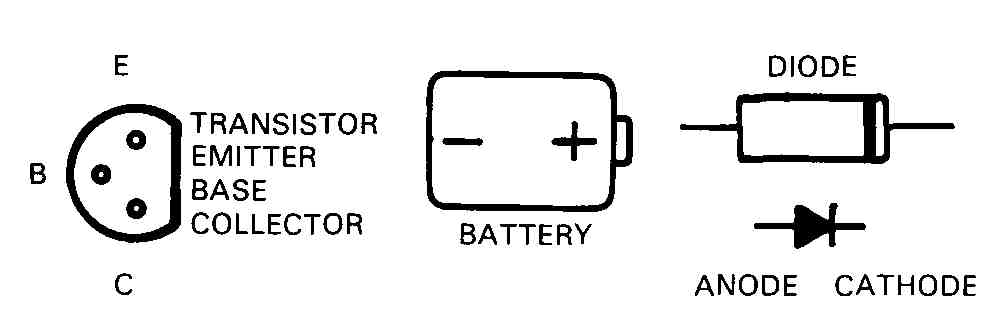
FIG. 22. Polarized components with their leads identified.
REVIEW QUESTIONS
1. What three things are considered when we choose a wiring method?
2. What information is normally included in the wiring list?
3. Name two types of wires.
4. What is the advantage of stranded wiring?
5. What does 7/26 mean when we relate it to wiring?
a. 7 strands wrapped around 26.
b. 7 gage wire wrapped by 26 gage wire.
c. 7 strands of 26 gage wire.
d. 7 strands that total 26 circular mills.
6. Gage of wire is determined by the _____ ______ _____ Standard.
7. What is affected by wire length and diameter?
8. How do we use bus wire?
9. Shielded or __________ cable reduces interfering radiation.
10. A point-to-point diagram shows the physical arrangement of the components. What other information does it convey?
11. When would we use pictorial point-to-point diagrams?
12. What is the advantage of a highway diagram?
13. Cable assembly drawings will contain what information?
14. Why is the cable harness assembly drawn to scale?
15. What are the advantages of cable harnesses?
16. How are harness posts used?
17. Cable straps or lacing serve what function?
18. What determines the type of termination a wire will make?
19. The most economical termination method with automation is (soldering, crimping, wrapping).
20. Subassemblies on diagrams are shown in phantom lines.
PROBLEMS
PROB. 1. Using the test simulator schematic, FIG. 23, create a wiring list and parts list. Wiring between the printed circuit connectors, switches, test points, and connector needs to be listed. See FIG. 2 for wire list format. Wiring shorting out the switches has been accomplished in a subassembly so do not list.
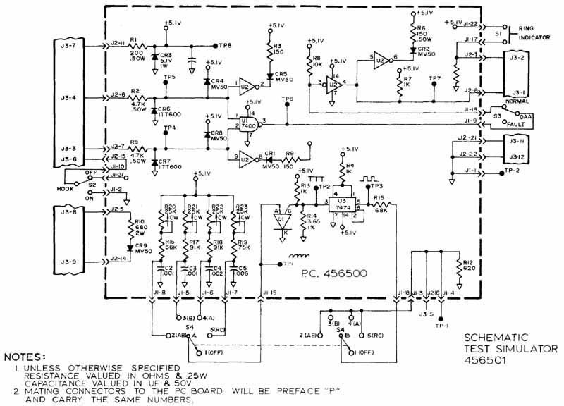
FIG. 23. A printed circuit board, enclosed in dashed lines, and the connecting
lines to switch, test points, and an external connector, J3. Create a wiring
list and parts list.
PROB. 2. Draft a point-to-point wiring diagram for FIG. 24, the test simulator. Check FIG. 25 for component numbering and sizes. FIG. 26 will show panel mounting positions. Use the wiring list generated in Problem 1 to aid in this problem. If the wiring list was not completed use the information indicated in Problem 1. Start by “undoing” the assembly in FIG. 11A. AU wire lengths determined at assembly. Note: Wiring is installed with panel turned up side down. See FIG. 27.
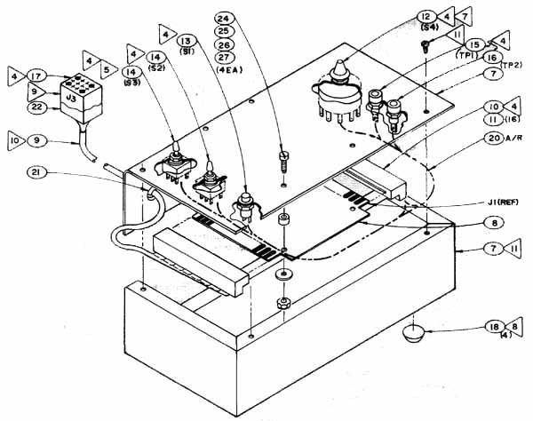
FIG. 24. An exploded view of a test simulator package. This is the
final assembly drawing. Draft a point-to-point diagram.
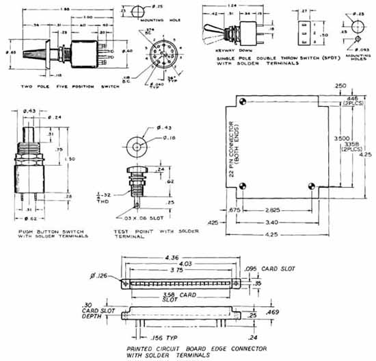
FIG. 25. These components used in the test simulator project are important
for planning the case mounting hardware. The Section problems refer several
times to this Figure.
PROB. 3. Create a highway diagram using information described in Problem 1 and 2. FIG. 27 shows the layout paths for the highway. Use as much information as you can from above problems.
PROB. 4. Using all the accumulated information from above problems, create a wire harness drawing. Note: This drawing is drafted to a 1/1 scale. It will be a tool for manufacturing. Check FIGs. 23, 6-24, 6-25, and 6-26.
PROB. 5. Draft a baseline diagram of the test simulator. Use example in FIG. 1 2, for example. Assign a color to each wire.
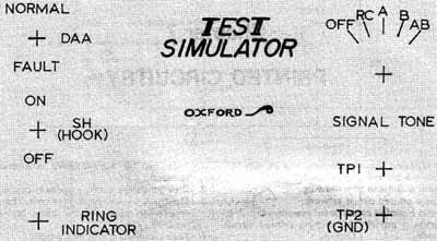
FIG. 26. The front panel of a test simulator. The switch and test point
positions are shown full scale. This is a silk- screen artwork for the
panel. Some of the information is needed in several Section problems.
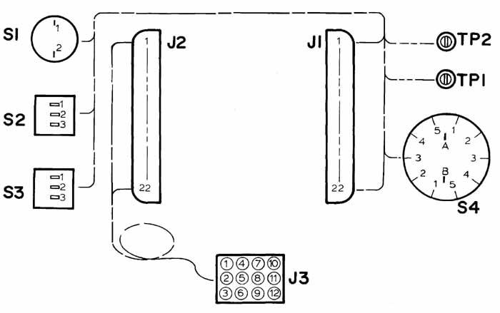
FIG. 27. This is the basic layout of the highway diagram for the test
simulator. Complete this highway diagram using wire destinations given
on the schematic.