AMAZON multi-meters discounts AMAZON oscilloscope discounts
PART 2
Goals
1. Demonstrate an understanding of analog and digital meters
2. Demonstrate an understanding of oscilloscopes and their uses
3. Demonstrate an understanding of test and measurement instruments for components and signals
4. Demonstrate an understanding of the role of the PC in test and measurements
5. Demonstrate an understanding of equipment reliability and surface mount repair
6. Demonstrate an understanding of safety testing and electromagnetic compatibility.
Meters and data
Since the servicing of all electronic circuits calls for the use of measuring instruments, it is necessary to be able to make effective use of these and of the readings obtained from them. The two most important types of circuit measurements are d.c. voltage and current readings, using a multirange meter (multimeter), and signal waveform measurements that are best made using a oscilloscope. One preliminary point of importance is that, whatever the type of measurement made in an electrical or electronic unit, the very act of connecting the instrument into the circuit will have some influence on it and so affect the reading obtained.
Apart from the ease of reading an instrument and its ability to produce consistent readings, the most important features of any test instrument are its accuracy, resolution and linearity.
The accuracy of any meter is quoted in percentage of error relative to some particular standard value. If a meter has a declared accuracy of 5% (say 5 mV in 100 mV), there is little point in trying to interpret a reading to an accuracy of 1 mV. As a useful guide, read only to the nearest half division on the indicated scale. A high-grade analog meter usually has a mirror-backed scale plate so that the pointer can be accurately read by avoiding parallax errors. The operator's head is moved from side to side so the reflection just disappears behind the pointer (FIG. 1b). A digital multimeter often has a better accuracy than an analog one that uses a moving coil unit. For general-purpose instruments, an analog multimeter may have a declared accuracy of 0.5%, while the corresponding digital instrument may produce a figure of 0.025%. However, the least significant digit often varies while taking a reading, so that the accuracy would typically be declared as 0.x% 2 counts.
Resolution refers to the smallest distinction between readings that can be obtained. For the analog instrument this is typically the nearest half division mentioned above. For the digital device it is the value represented by the least significant digit.
Linearity represents a scaling that varies by equal deflections per unit of measured quantity. For an analog instrument with poor linearity this is usually obvious by the cramping of scale readings towards one end. The linearity of a digital multimeter is not similarly obvious from the reading of the display, but can still exist as an unwanted feature of the measurement system.
Periodically, the accuracy of all instruments should be checked against some standard voltage cell or an instrument that has been similarly calibrated and can be used as a transfer standard. Since this property is often temperature dependent it is usual to make any readjustment at 20ºC. The calibration against a transfer standard meter can easily be affected by connecting the meters to be compared either in parallel (voltage) or in series (current) when coupled to the same source.
Unlike multirange instruments used for service purposes, panel meters FIG. 1(c) are often built into control systems monitors. While these meters may well be scaled in volts, amps or ohms, they may equally well be scaled in degrees Celsius, kilograms or any other parameter such as liters of liquid flow per second. They may also contain a limited number of shunts and multipliers so that the single meter can be switched to indicate a small number of different parameters. Otherwise, analog panel meters are simply basic instruments used for a very specific purpose. In most cases modern panel meters are microprocessor-based systems which can include features such as event recording and replay, peak hold and alarm outputs or even network connections.
===
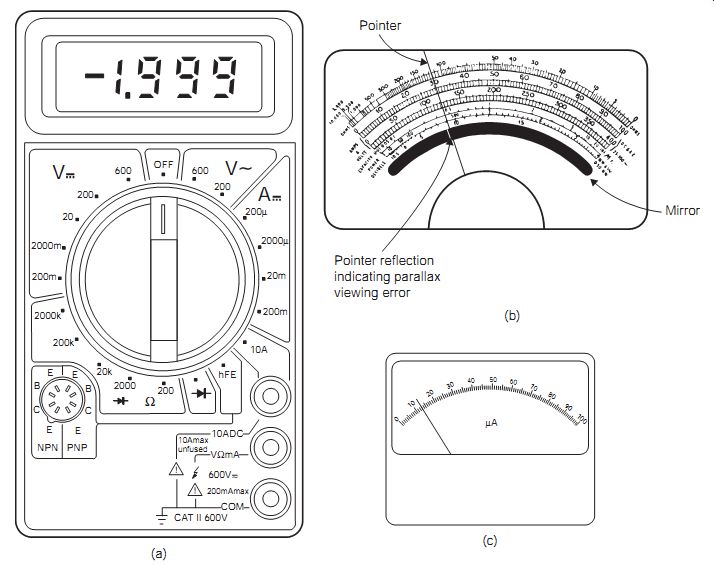
FIG. 1 (a) Typical low-cost digital multimeter, (b) mirrored scale analog multimeter scale, and (c) 100 µA moving coil panel meter
===
Multimeters are instruments capable of measuring several ranges and parameters, often d.c. voltage and current, resistance and a.c. voltage. Some multimeters include a.c. current scales, usually more expensive types, because such readings have an acceptable accuracy only if the meter includes an expensive current transformer, or 'true r.m.s.' analog or digital signal processing circuitry.
Both analog and digital multimeters (FIG. 1a) are in general use.
Analog multimeters use a moving-coil movement which, because of its resistance, draws some current from the circuit under test. Digital multimeters, in contrast, contain no moving parts; the reading appears as a figure displayed on a readout similar to that of a calculator. A separate power sup ply, usually a battery, is used, so that practically no current is drawn from the circuit under test. Either type of meter will have a measurable input impedance whose value will affect the readings. Analog meters referred to as field-effect transistor input volt ohm amp (FET VOM) combine the input amplifier circuitry of the digital multimeter with a precision moving coil meter. These instruments are usually found in specialist laboratory applications.
====
Connect the circuits shown in FIG. 2 and use first an analog and then a digital multimeter, each set for a 10 V range, to measure the voltage V. Note the results, and check by calculation that the value of V ought to be 4.5 V when the meter is not connected. Are the meter readings significantly different for (a) the low-resistance circuit, and (b) the high-resistance circuit? Analog meters are described as having a input resistance of so many ohms per volt; compare this rating with the circuit measurements you have made.
EXPERIMENT 1
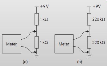
FIG. 2 Circuit for comparing meters: (a) low resistance, and (b)
high resistance.
====
As the results of the practical show, the lower resistance of the analog meter can cause the readings taken to be unreliable. These voltage readings will always be in doubt when the resistance of the meter itself is not high compared with the resistance across which the meter is connected. For reliable readings, the resistance of the multimeter must be high compared with the value of resistance at the point where the measurement is taken. At least 10 times higher is the minimum, and even at this level, you can expect to find some difference between the true voltage (when no meter is present) and the measured value. The digital meter, with its high resistance, is definitely superior to an analog type in this situation.
Range extension using multipliers and shunts
The basic meter resistance is that of the moving coil, which is both temperature dependent and subject to significant manufacturing tolerance. To reduce the effects of these variations on accuracy the meter is usually connected in series with a much larger resistance to swamp the variations in coil resistance.
If a basic meter with 50 µA full-scale deflection (FSD) and 1 kO resistance is to be used to measure voltage, then the largest voltage that can be measured is 1 kO x 50 µA = 50 mV. In order to measure a higher voltage, say 10 V, a series multiplier resistor needs to be connected in series with the meter (FIG. 3a). The multiplier needs to drop 10 V-50 mV when 50 µA flows through it, so its value is 199 kO. This gives a total resistance of 200 kO for the 10 V meter. The meter is then said to have an input resistance of 20 kO/V.
Extending the current range of a meter can be done in a similar way, using a parallel shunt resistor FIG. 3(b). Taking the same 50 µA meter movement with 1 kO resistance as the previous example, we can use it to measure a current of 2 A by selecting a shunt which drops 50 mV when 2 A flows through it and the 1 kO meter resistance in parallel, that is 50 mV/2 A = 25 mO. The total resistance is thus 25 mO, composed of 1 kO in parallel with a 25.000625 mO shunt, which would be a short thick piece of cop per wire. If you look inside a multimeter this is exactly what you will find between the A input and the common terminal. Note in this case that the difference in meter and shunt resistance is so great that the effect of the meter resistance is negligible and a 25 mO shunt would be used.
==
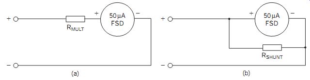
FIG. 3 (a) Using series 'range multiplier' resistor to extend the
voltage range of a moving coil meter, and (b) current shunt to extend the
current range
===
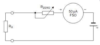
FIG. 4 Adding a resistance range to a meter
===
Resistance measurement
The basic analog meter can be adapted to add a resistance range to the multimeter circuit. The battery, shown in FIG. 4 as 1.5 V, is used to drive a series current through the meter and the resistance under test. The variable resistor R1 is used to set the meter to FSD with a short-circuit across the test terminals which represents the point of 0 ohms. The open circuit condition should produce a meter deflection of zero and this represents infinite resistance ( ). The meter now measures in the reverse direction.
The range of such an instrument can be modified simply by increasing the battery voltage to, say, 3 V. Meters of this type normally have a positive potential on the common terminal black test lead and vice versa. It is thus important to recognize this point, particularly when measuring non linear devices such as diodes and transistors. A similar system can be used to provide a resistance range on digital multimeters, with the advantage that much higher resistance values can be measured.
The simple circuit known as the Wheatstone bridge can provide accurate measurements over a very wide range of values. As shown in FIG. 5, it consists simply of three resistors, one of which is variable, a centre zero moving coil d.c. meter and terminals across which the unknown resistor is connected. The bridge is energized by a low d.c. voltage (usually a 1.5 V cell). The resistors R1 and R2 are referred to as the ratio arms, which can be switched in or out of circuit as necessary to provide resistance ratios of R1:R2 of, typically, 10:1, 100:1 and 1:100, 1:10. The unknown component is connected to provide Rx and the bridge circuit is balanced when there is zero current through the meter (at centre scale). The balance condition occurs when R1Rx = R2R3, or when Rx = R2R3/R1.
===
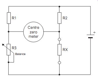
FIG. 5 Basic Wheatstone bridge circuit
===
The ratio arm values are known and the value of R3 is found from the scale surrounding the control knob. This allows a simple calculation to be made which provides the value of the unknown to a very high degree of accuracy. The bridge type of circuit is used extensively for measurement and is also the basis of the full-wave rectifier circuit.
By connecting a d.c. moving coil meter to a bridge rectifier circuit, a.c. voltages are converted into d.c. (FIG. 6). The d.c. meter itself can be fitted with shunt and multipliers so that its basic range can be extended. When used in this way, the meter reads the average value of the sine wave input, equal to 63.7% of the peak value. By modifying the scaling of the meter, this can be redrawn to indicate the r.m.s. value instead. Since the r.m.s. value is 70.7% of the peak a.c. value, this scaling or form factor for a sine wave is equal to 0.707/0.637 = 1.11.
Different form factors are needed for other waveforms. It should be noted that the bridge rectifier introduces a voltage drop of 1.4 V or so into the circuit, so this circuit is inaccurate for a.c. voltages much below 20 V.
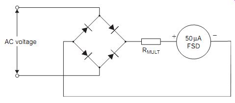
FIG. 6 Measuring a.c. voltage with a bridge rectifier
===
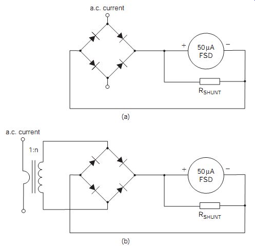
FIG. 7 Measuring a.c. current: (a) low current, and (b) high
current measurements using a current transformer
===
When shunts similar to those used for modifying the ranges of a d.c. meter are used for a.c. measurements, their impedance, which varies with changes in the magnitude of the current, would require the use of separate scales for each range. This is the chief reason why a.c. shunts are only found in very low-cost instruments. To overcome this problem, a current transformer (FIG. 7b) with a tapped secondary winding is used instead. This has a low-impedance primary winding and a high-impedance secondary, so that the secondary voltage is proportional to the primary current.
For example, If the basic 50 µA FSD meter were to be used to measure 5 mA a.c., then the transformer would need to have a 1:100 turns ratio. In this case, the conversion between average and r.m.s. scaling can be accomplished within the current transformer by multiplying the turns ratio by the standard form factor of 1.11. Thus, the required turns ratio becomes 1/100 x 1.11 = 1:90. The a.c. output voltage is finally rectified using a standard bridge circuit as shown in FIG. 7.
In theory, the shunts and multipliers used to extend the ranges of basic analog instruments could be chosen from separate, high-stability, high-accuracy standard components. However, if these separate resistors are switch selected while the meter is left connected to a circuit under test, there is a very high chance that the full test voltage or current can be momentarily applied across the meter, with disastrous results. To avoid this situation, shunts and multi pliers are generally wound in a series configuration and tapped at the appropriate points. By using such universal shunts or multipliers, the problem mentioned above can be nearly completely avoided.
Digital multimeters (DMMs) generally have much less effect on the circuit being measured. Most of them have a constant input resistance of 10 M or more, and few circuits will be greatly affected by having such a meter connected into them. The operating principle is that the input voltage is applied to a high-stability, high-resistance potential divider which is usually connected to an operational amplifier (opamp) to provide further isolation. The output of the opamp then provides the input to an analog to-digital converter stage (FIG. 8). Typically, a microprocessor circuit drives the display, provides functions such as peak hold, and can also out put data to an RS232 serial link or other data communication device. The range switch selects the part of the potential divider to be used, and the position of the decimal point on the display.
A point to note is that although a digital meter may indicate a voltage reading to several places of decimals, this is not necessarily more precise than the reading on an analog meter.
===
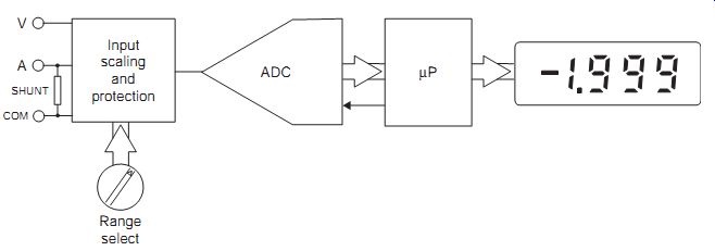
FIG. 8 Simplified block diagram of a digital multimeter
===
DMM devices are often specified by the number of digits in the display.
However, there is an extension to this technique to allow for over-range readings. An extra leading digit is either displayed as a 1 or it is not displayed. Such a DMM would be described as having a 3½ digit display. A further addition provides for a minus sign (-) to be displayed when reverse polarity is encountered. This adds an extra ¼ digit. Therefore, a basic three digit display with these features would be described as a 3¾ digit meter.
Meter features
Frequency response becomes important for a.c. measurements. While most multimeters are built to monitor power frequencies, they can provide a reasonably accurate assessment of voltages or current, up to about 20 kHz for an analog instrument and perhaps 100 kHz for a digital multimeter.
Autoranging allows a multimeter to select automatically the correct range of values, when the specific function has been preselected by the user. The feature cannot easily be built into an analog instrument, but can readily be included in the facilities of a DMM, particularly those instruments that are software controlled. Basically, if the reading on a particular selected scale has been overdriven, the meter automatically shifts the scaling up to the next highest level. However, overload can still occur if the meter tries to exceed the maximum permitted level.
Capture of readings applies chiefly to the DMM and represents the time taken for a reading to reach equilibrium. For the analog instrument the pointer settles in a time controlled by the damping created by the back electromotive force (emf) due to the pointer movement. In the DMM, this feature can be affected by the dither in the least significant digit (1 or 2 counts).
Peak readings: analog meters measure the average value of the input quantity, which in the case of d.c. is also the peak value. However, for a.c. quantities, the scaling is modified by the form or scaling factor. Digital meters can be designed to measure true r.m.s. values for any waveform.
Clamp-on current measurements: when attempting to measure the current flow through, say, a large power cable, it is not convenient to break the cable to insert a meter. For these applications there is a device which is effectively the secondary of a current transformer wound on a split core that can be opened to encompass the cable and then read off the current flow directly. Such an instrument can include within the split core clamp a Hall effect device that responds to the magnetic effect of d.c. current flow so that the meter interprets the strength of this field in terms of the d.c. current that created it, and this allows both a.c. and d.c. current measurements to be made. It is important to ensure that only one wire, e.g. the supply (or live for a.c. mains) wire or the return (or neutral) wire, but not both, passes through the clamp, otherwise the currents in the two wires will cancel each other out.
Transistor and diode tests: digital multimeters often have facilities for testing transistor hfe and diode forward voltage drop. These can be useful for matching devices, but are not usually very accurate. The transistor hfe measurement usually operates by applying a small fixed current, e.g. 100 µA, to the transistor base emitter junction and measuring the current flowing in the collector circuit. Similarly, diode forward drop operates by trying to force 5 mA through the diode and measuring the voltage required to do so.
Overload protection: there is a number of steps that the user can take to avoid damaging a meter through overloading:
• Take note of the manufacturer's stated safe working levels for both a.c. and d.c.
• Avoid measuring voltages or currents that exceed the maker's recommendations on any particular range.
• Avoid trying to measure volts or current with the meter switched to the resistance range.
• Observe the stated safe environmental working temperature.
Apart from the obvious use of a fuse in the test lead circuit, particularly for current ranges, back-to-back silicon diodes (antiparallel diodes) are often included in parallel with the meter movement. These develop a low resistance on overload and thus place a short-circuit across the meter movement.
Analog meters may have a ballistic mechanical system that physically trips a pair of contacts to remove it from the circuit if the pointer approaches the end stop too quickly. Moving coil meters should always be stored or trans ported with a short-circuit across their terminals. This damps the movement due to the back-emf created by physical movement. Electronic driven digital or analog meters can be protected by using the crowbar effect of a pair of thyristors wired across the input.
Because of the flexibility of the DMM, its operation can easily be extended to provide measurements of capacitance, frequency, sound level, temperature, humidity and other parameters, as well as allowing for simple diode and transistor testing.
===
EXPERIMENT 2
Connect two meters, one digital and one analog, to the centre-tap of the potentiometer, illustrated left. Switch the meters to their 10 V ranges and switch on the 9 V supply. Observe the readings as the potentiometer shaft is rotated to and fro. Which meter more closely follows the changes in the output? Check also how quickly you can read each meter when the voltage is steady. Which meter is easier to read?
===
Making measurements
• Start with the meter switched to its highest voltage range.
• Connect the meter with the circuits switched off.
• For voltage measurements, always use the highest range that gives a readable output.
• For current measurements, always try the highest current range first.
• Never leave the meter switched to any current range when you have temporarily stopped using it.
• Make sure you know which scale on the dial to read before you try to take a reading.
• Never leave a meter switched to ohms range when taking voltage or current readings.
In most circuits, the use of a multimeter for current readings has much less effect on the circuit than when it is used for voltage readings. To make a current reading, however, the circuit has to be broken, and this is seldom easy on modern circuit boards.
A few audio and television circuits make provision for checking currents by having a low resistance permanently connected to the current path.
By measuring the voltage across this resistor, the current can be calculated using Ohm's law, I = V/R. Because the resistance so placed in the circuit is very small, the effect of connecting the meter into the circuit is negligible.
Voltage readings are used to check the d.c. conditions in a circuit. These readings are usually made when no signal is present. Readings that are taken when a pulse signal is present will always give misleading results because of the effect of the pulse signal itself on the meter. For this reason, voltage readings shown on a circuit diagram are usually specified as 'no-signal' voltage levels, or are shown only at points in the circuit where the signal is decoupled so that only d.c. is present.
When voltage readings are shown on a circuit diagram, they are always average readings which may vary from one example of a circuit to another because of component tolerances. In addition, the actual readings taken in a circuit may be different from these values, either because of tolerances or because of the use of a meter with a different input resistance, even if the circuit is working quite normally. Some experience is needed to decide whether a voltage reading which is higher or lower than the stated average value represents a fault, or whether it is simply due to tolerances or meter resistance. In general, a voltage varying from the norm by up to 10% is usually due to tolerances, but a voltage variation that shows a transistor to be nearly bottomed or cut-off in a linear stage always betrays a fault condition.
Root mean square values
When d.c. flows through a circuit it dissipates heat due to the power being generated, I^2 R=W. Similarly, when a.c. flows through a circuit power is again dissipated, but how is this to be compared and measured? For a sine wave, the average voltage or current flowing will be zero, because each positive excursion is matched by an equal but opposite polarity negative swing. But we know that even a resistor passing a.c. gets hot, so how can we measure this effect? The root mean square (r.m.s.) value is described as that value of a sine wave that produces the same power or heating effect as an equivalent d.c. value. For a sine wave, this can be calculated first by squaring the waveform and then taking the average value of this, either V2 or I^2 . Now, by taking the square root of this value, either VI 22 or , we return to a particular value of V or I, which is termed the r.m.s. The process is shown.
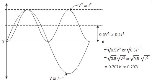
FIG. 9 Derivation of r.m.s. value for a sine wave
Since the power dissipated or the heating effect is only truly applicable to the sine wave a.c. drive, any other wave shape would produce different results. For example, it can easily be shown using the technique explained above that the average, peak and r.m.s. values for a square wave are all identical. A method that can be adopted for calibrating a non-sinusoidal alternating waveform relies on the basic definition. By using the power of an unknown wave shape to drive an incandescent lamp and a controllable true sinusoid (or d.c.) to power an identical lamp, increase the drive to and monitor the sine wave drive r.m.s. level. When the two lamps glow with equal brightness as measured by a light meter or temperature sensor, the r.m.s. value of the arbitrary wave shape is equal to that of the sinusoid or d.c. drive power.
Networked instruments
The concept of automated test equipment (ATE) has been progressively introduced into the servicing environment, and this involves simple local area networks (LANs). Not only can the networked system now provide service information to many test and repair stations, such systems can also be used to monitor and log data from various test points for future analysis.
Furthermore, the computer monitor can be converted into a range of test instruments, all under software control.
RS232 is probably the oldest interconnection standard for linking a computer to an item of ancillary equipment. During its more than 25-year existence, the standard has undergone more than six major changes and is still valid today. The original RS232 standard was designed to provide two transmit/receive channels for simultaneous full duplex communications using bipolar signals of 15 V level. The positive and negative excursions represented logic 1 and 0, respectively. Using a multicore cable and 25-pin D-type connectors, a maximum signaling rate of 20 kbits/s could be achieved over a distance of 20 m. Later versions of RS232 (such as RS423) have used both 15-pin and nine-pin D-type connectors with multicore cable and bipolar signals at both 3 and 5 V levels in a single simplex transmit/receive mode.
In all the RS232 versions, the system transmits in the bit serial mode in both directions and the system standard provides for data, timing and control signals. The system is designed to connect a data terminal equipment (DTE), usually a computer, a data communication equipment (DCE) or a peripheral device. The primary channel is normally used for data, while the secondary path carries the control and timing signals. However, both channels may be configured for both half-duplex and full-duplex transmission modes.
FIG. 10 shows the standard pinning arrangement for the RS232 DTE connector, and FIG. 10(c) shows the full implementation of the pin allocation. Few applications now make use of all of these pins.
===
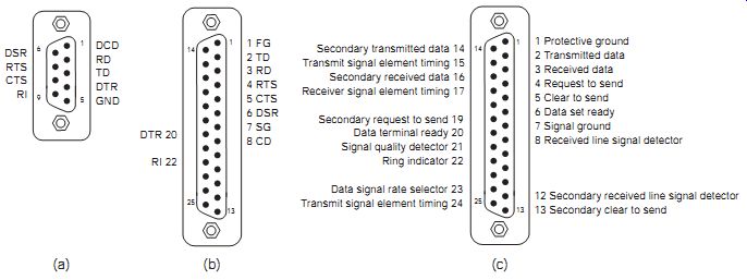
FIG. 10 RS232 pin connections: (a) nine-pin DTE, (b) 25-pin DTE,
and (c) full 25-pin DTE
===
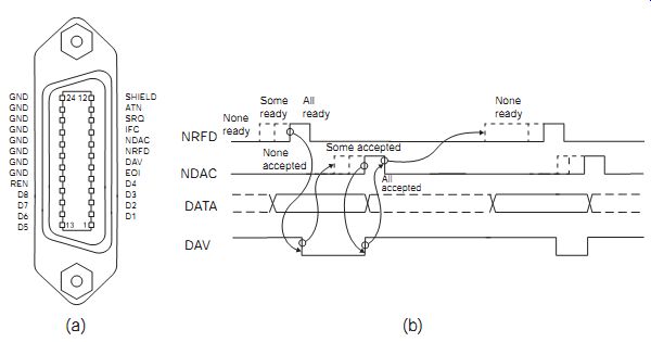
FIG. 11 IEEE-488 connector: (a) pin out, and (b) timing of a talker-
listener IEEE-488 exchange. Where more than one listener exists, DAV is
not asserted until all listeners are ready.
==
For a modem cable using the full 25-pin implementation, the two connectors are configured pin for pin, but for the null or non-modem operation, pins 2 and 3 (RXD and TXD) and pins 5 and 20 (DTR and CTS) are cross-connected. This type of cable is used, for example, when the cable is connecting two computers together so that they can pass data in either direction. The changes for the nine-pin cable are pin to pin for a modem cable, and for the null-modem, pins 2 and 3 (RXD and TXD) and pins 4 and 8 (DTR and CTS) are cross-connected.
The IEEE488 data cabling system is also known as general-purpose interface bus (GPIB) and Hewlett-Packard instrumentation bus (HPIB) and is a standard interface bus designed specifically for instrumentation purposes. It consists of eight data lines: three control lines and five lines for interface control. It is based on a standard male/female back-to-back 24-pin connector and cable system, which provides for 8-bit parallel data transfer rates of 1 Mbyte/s. The transmission system uses unipolar negative logic signaling (high = 0, low = 1). Fifteen devices with different data rates may be connected to the bus at any one time, but the total transmission line length is restricted to 20 m maximum.
In the latest version, IEEE488.2, the parameters have been upgraded.
Three types of device may be connected and these are described as talkers, listeners or controllers. For example, a meter, keyboard or sensor may be described as a talker, a printer or a recorder as a listener and a computer as a talker-listener. By comparison, a DMM that needs to be programmed in situ and then be able to transmit results is also a talker-listener. Although the network may contain more than one computer, one is designated as a master or controller and allocates the bus to individual devices in turn.
Each device on the bus has its own unique address carried in a specific byte. The five least significant bits (LSBs) represent the address, bits 6 and 7 set the talk/listen function, with 01 = listen and 10 = talk. The most significant bit (MSB) can generally be ignored.
• ATN (attention) is the main controller signal. When this is low, the controller is sending commands or addresses to the interface connected devices. When it is set high, it signifies to the talkers and listeners that the bus is ready to transfer data.
• IFC (interface clear): by driving this signal low for a short period (100 µs) the controller resets the interfaces of all the devices on the bus.
• REN (remote enable): this line is held permanently low when the inter face is working.
• SRQ (service request): devices use this line to request service from the controller. For example, an instrument can signal that it is ready to read after taking a measurement.
• EOI (end or identify): this line is driven low by an active talker while it is transmitting its last byte as a form of end of data string. It can also be used by the controller.
• DAV (data valid).
• NDAC (not data accepted).
• NFRD (not ready for data).
When ATN is low (1), all devices must listen for interface messages, then if a device is addressed, it must be ready for a data transfer as soon as ATN goes high (0). Every byte is transmitted under the control of three handshake lines, DAV, NRFD and NDAC.
An active talker with data to transmit monitors the NRFD line and if this is low (1), the listeners are not ready to receive data. When NFRD goes high (0) and the listeners maintain NDAC low (1), the data is not being accepted.
When the listeners set NDAC high (0) and NFRD low (1), the data can be transferred.
At the end of each transmitted byte DAV goes low (1) to validate the data transfer.
QUIZ:
Q-1. Given an equal specification, what advantage makes digital meters easier to use than analog meters?
(a) larger display
(b) no parallax errors
(c) does not load the circuit
(d) does not require a battery.
Q-2. Using the 2 V range of a 20 000 O/V analog meter, a voltage of 0.4 V is measured across a 100 kO resistor in circuit. What is the real resistance in circuit?
(a) 20 kO
(b) 29.6 kO
(c) 71.4 kO
(d) 100 kO.
Q-3. Using a 1 mA FSD meter with an internal resistance of 1 kO, what shunt resistor would be required to measure 4 A d.c. at full scale?
(a) 4 O
(b) 1 O
(c) 0.25 O
(d) 0.025 O.
Q-4. A current transformer is used to measure the current in a circuit. What turns ratio should be used to measure 2 A r.m.s. on a 1 mA FSD 1 kO meter?
(a) 1:1400
(b) 1:1800
(c) 1:2000
(d) 1:2200.
Q-5. Which of the following features is not found on an analog meter?
(a) auto ranging
(b) 10 MO input resistance
(c) true r.m.s. current measurement
(d) transistor hfe tester.