AMAZON multi-meters discounts AMAZON oscilloscope discounts
IN SECTION 2 we saw that each electronic component had its own schematic symbol. We will now look at some of these symbols as they are used in a circuit and see how to put the circuit together.
The schematic diagram is the heart of any electronic project. If you can read and understand it, you can built the whole project with little or no written instructions.
Pictorial diagrams that show a picture of the parts and the wires that connect them are frequently given along with the schematic diagram. These pictorials are suitable for the beginner or for a simple project. But, as projects become more complicated, the pictorial diagram becomes useless. One of the big problems with pictorials is the fact that the man drawing the diagram has little choice as to where he places the parts. This results in a tangle of wires as the drawing gets more complicated.
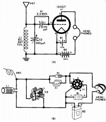
Fig. 55-Schematic far a simple radio.
A schematic diagram, if it is drawn right, will have few crossing wires. There are certain standard ways of drawing these diagrams that make them easy to follow. All stages of a circuit are laid out in a straight line, with the input on the left and output on the right. Auxiliary circuits, such as oscillators, are drawn below the tube they affect. High-voltage wiring, such as the B+ wires, is usually drawn above the tube; low-voltage wiring (filaments or grounds) is drawn below the tube.
Power-supply wiring is usually off to one side, at the bottom of the drawing.
It would be impossible to follow these conventions in a pictorial diagram. Therefore, each pictorial is a one-shot affair as far as learning is concerned. But, every schematic understood is a step toward better understanding of electronics.
Placement of the symbols on the schematic diagram has no relationship to the actual placement on the assembled chassis. The schematic only shows the connections of the parts. Where the parts go on this chassis is up to you or to the man who designed the equipment.
In a schematic, connections between wires are shown by a dot.
If the wires cross, but do not connect electrically, no dot is used. A schematic for a simple receiver is shown in Fig. 55A. If we mentally substitute the parts indicated by symbols it would look something like Fig. 55B.
The first step in building the receiver is to lay out the chassis and mount the parts that are to be screwed to the chassis. These include the tube socket, variable capacitor, and antenna coil. Because the set is battery operated, mount a screw-terminal strip to which the batteries can be connected. A set of binding posts can be used to connect the headphones. With all the mechanical work done, we can proceed with the wiring using the schematic as a guide.
The left side of the diagram shows that the antenna, one side of the coil, and one side of the tuning capacitor should be connected together. Two pieces of wire will take care of this. Next, the battery ground terminal, the other side of the coil, and the other side of the tuning capacitor are all connected together.
(The terminal on the tuning capacitor attached to the frame is always the ground side.) The schematic also shows that the mica capacitor C1 and the resistor R1 should be connected directly together (in parallel). One end of the combination goes to pin 5 of the tube socket; the other end goes to the end of the tuning capacitor that is connected to the antenna.
Number 3 terminal goes directly to one side of the headphones.
The other side of the phones goes to the + terminal of the battery.
Hook this wire to the terminal of the battery terminal board that was mounted on the chassis.
There are two remaining connections to the tube socket. Socket pin No. 2, the "A-," the "B-," and ground are all connected together.
In the AM broadcast band, where this set will operate, it is not important where the wires join, but they must all be connected together.
A wire from socket No. 2 should go to the frame (ground) side of the tuning capacitor. A wire from the frame should go to the A- and B lugs on the terminal strip.
The wiring is finished, except for pin No. 7. That goes to the + side of the A battery. Connect a wire to that lug on the terminal strip.
Label the connections on the terminal strip with a pencil so that the batteries will be hooked up properly.
Clip a wire from a water pipe or bedspring or something onto the "ground" terminal, drape 10 feet of wire over the window frame for an antenna, connect the phones, and, presto, the job is completed. You should have an operating radio. That's all there is to using a schematic diagram!
Troubleshooting
Schematics are also useful after you have finished building a project. If the circuit doesn't work on first try or if something should go wrong with one of the components at a later date, the schematic will be useful in tracking down the cause of the trouble. It is a good idea to keep a file of schematics for all projects so that you can refer to them easily if trouble occurs.
When a circuit does not work after the wiring is completed, there are three main reasons-poorly soldered joints, wiring errors, and defective components. The fastest way to locate the trouble is to make a systematic check of the wiring and soldering. First inspect each terminal for signs of poor soldering technique. This can be found by looking for a joint that has a granulated rough surface instead of the smooth shiny surface of a good joint. When you find a cold solder joint, touch it with a hot soldering iron until the solder begins to flow.
The next step is to make a quick check of the wiring. A fast way to do this on simple projects is to look at the schematic and count the number of wires connecting to each major terminal, such as tube socket pins and terminal strip. Then look at that terminal in the wired circuit and check to see that the numbers match. The best way to check wiring, although the most time consuming, is to check each wire on the schematic and then locate it in the circuit. Check to see that it is connected between the proper points and then cross it out on the schematic with a colored pencil. Start at the left of the schematic and work across to the right, marking out the wires as you go. This method should show up any wiring errors. The procedure used for the circuit in Fig. 55 was as follows: Antenna goes to one end of coil (check wiring). From the same terminal, lead goes to pin 5 of tube through a capacitor and resistor in parallel (check wiring). The variable capacitor is connected across coil terminals and second terminal of coil goes to ground (check wiring). This procedure is followed until all the wires on the diagram have been accounted for.
If you have a voltmeter and ohmmeter handy, they are very useful in locating the source of trouble in a circuit. (Some circuits for building your own meter are given in Section 8.) By using a meter, you can narrow down the trouble from the whole circuit to one individual spot. For example, one of the first things to check is the B+ voltage throughout the circuit. Start at the source of this voltage, the power transformer. Using the voltmeter, check to see if there is voltage present at the output of the transformer. (This is a.c., so use the proper meter setting.) If there is voltage at this point, move to the output of the rectifier (switch your meter for d.c. reading). If everything is all right there, move your meter to the plate terminal of each tube. If you find a place where there is no B+ voltage, you know that the trouble is between there and the rectifier. This is where the schematic diagram can be useful. Trace the circuit on the schematic from the rectifier to the point where there is no voltage. Then work back from the plate of that tube, making voltage measurements on each side of the components. When you find a part that has no voltage on the plate side and does have voltage on the rectifier side, you have found the defective component.
Another check point is the filament circuit of the tubes. First check with the voltmeter to make sure that there is filament voltage being supplied by the transformer (a.c. again). Then connect the meter across the two tube socket pins that are connected to the tube filaments. The voltage reading here should be about the same as the first two digits in the tube number (for a 6SN7 -6.3 volts, for a 12AU6 12.6 volts, for a 50L6 -50 volts). If all of these voltages are O.K., you can be sure that the filament wiring is all right; but you still have to check the condition of the filaments inside the tube. To do this, use an ohmmeter. Remove the tube from the socket and set the ohmmeter to its lowest scale. With the test leads of the meter connected across the filament terminals of the tube, there will be a low reading on the scale if the tube is all right. If the filament wire is broken inside the tube, there will be no movement of the meter pointer.