AMAZON multi-meters discounts AMAZON oscilloscope discounts
LEARNING OBJECTIVES:
Upon completion of this Section on photographic processing, the student should be able to:
1. Become familiar with the operation of a typical copy camera for photo graphically reducing printed circuit artworks into phototools.
2. Expose and process photographic film.
3. Use the 21-step exposure table in developing film.
4. Use the technique of contact printing to generate positives from reduced negatives.
0. INTRODUCTION
After the taped conductor pattern artwork masters and the solder and marking mask artworks have been completed, they are photographically processed into working tools that will be used to fabricate the finished printed circuit boards. These resulting positive or negative photographic films are commonly known as phototools.
This Section begins with a discussion of the setup, use, and adjustments of a typical copy camera for photographically reducing artworks into photo tools. This is followed by a presentation of films, chemicals, and bath preparations as well as film processing. Also included is the technique of 1 : 1 scale contact printing to obtain image reversals.
The accuracy and quality of the phototools described in this Section will determine the quality of the resulting printed circuit board. For this reason, this Section is sufficiently detailed so as to emphasize careful attention to each of the processes described. Properly prepared phototools can avoid pc board fabrication problems.
1. PHOTOGRAPHIC REDUCTION OF THE ARTWORK MASTERS
Commercial photocopy cameras are capable of accepting artwork masters in excess of 48 by 60 inches. These masters may be reduced into positives or negatives by a factor of 5 : 1, 4: 1, or 2: 1. This reduction is dependent upon the type of lens available on the camera. One-to-one reversals of the master can also be made with the copy camera, but contact printing is a preferred process for this requirement. Contact printing is discussed in Sec. 3.
Artwork reductions made on a copy camera can be produced to a tolerance of ± 0.002 inch, although ±0.005 inch is the tolerance typically specified. The results of artwork exposure with a copy camera have high-quality line resolution, high contrast between light and dark areas, and negligible imperfections such as pinholes (voids) in the opaque areas of the processed film.
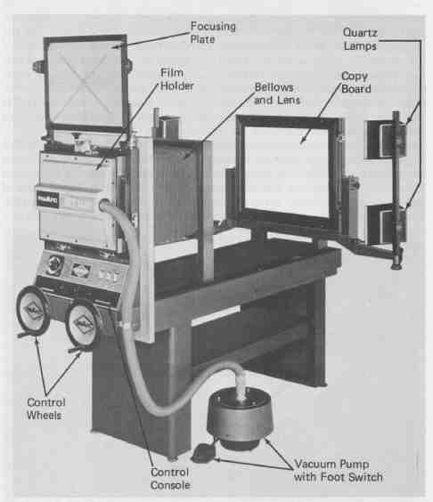
FIG. 1 Horizontal copy camera. nuArc Copy Camera Model SST1418
A typical commercial copy camera used for artwork reduction in the printed circuit board industry is shown in FIG. 1. This is a nuArc Copy Camera Model SST1418, which is capable of handling a film image size of up to 14 by 18 inches and artworks as large as 21 by 25 inches if front-lighted and 15 by 19 inches for back-lighted work. When used with the appropriate film, this cam era will provide excellent-quality exposures that are ideally suited for small- to medium-size pc boards.
The nuArc Model SST1418 copy camera will be described here to illustrate photographic procedures and typical camera operation. Other cameras used for printed circuit photography will involve similar operating procedures but may have distinctive differences so as to require the operator to consult the manufacturer’s instructions for any operating variations. The nuArc camera has eight basic components. These are (1) transparent glass copyboard with cover glass and translucent rear panel for backlighting; (2) four 800-watt quartz iodine lamps; (3) lens with diaphragm control, electric shutter, and cover; (4) bellows; (5) vacuum-frame film holder with vacuum pump and foot switch; (6) focusing plate; (7) two scale-adjustment control wheels; and (8) control console with focus, scale illumination, and master switches and lamp timer.
To operate this camera for reducing artwork masters, the procedure is as follows. First, the lens cover is removed. The copyboard is then rotated to the horizontal position for artwork loading. This is done by pulling out the frame release handle and gently lowering the frame. The cover glass is then unlatched and raised until the internal lock in the cover support arm engages to hold the cover open. The artwork to be processed is placed onto the transparent base of the copyboard and centered (see FIG. 2). To aid in obtaining consistent uniformly developed exposures, a transparent-to-opaque photographic step expo sure table is placed over a clear area of the artwork but outside the corner brackets so that is does not become a part of the resultant phototool. This is also shown in FIG. 2. (A detailed discussion of the use of a step table is given in Sec. 2, on processing film.)
With the artwork, together with the step table, positioned on the copyboard, the cover glass is lowered and locked into place. Raising the copyboard to its locked vertical position will establish the correct orientation for exposure. To result in maximum contrast between light arid dark areas of the artwork, backlighting is the preferred method. This is shown in FIG. 3. Note that the lamps are directed at approximately 45-degree angles to the rear translucent light-diffusing panel of the copyboard. With this arrangement, the artwork is uniformly and brilliantly illuminated without hot spots or reflections during film exposure.
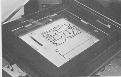
FIG. 2 Loading pad master and step table onto camera’s copyboard.
All adjustments for photoreduction are done at the rear of the camera. Power to the control console is first applied by depressing the tops of the master power rocker switch and the scale tape light switch. The scale reduction set tings are then made. Also located at the rear of the camera are two control wheels for adjusting both the reduction scale and the focus of the artwork image. One control wheel is labeled lens board and the other is labeled cop y board. Scale adjustment using these control wheels is made in conjunction with scale markings on two stainless steel calibration tapes that are viewed through 2 x magnifying lenses located at the center of the control console above the wheels. To adjust for a 2: 1 scale reduction, the copyboard control wheel is rotated until the accompanying calibration tape reads 50. Clockwise rotation of this wheel moves the copyboard away from the lens while a counterclockwise rotation moves it toward the lens. The lens board control wheel is then adjusted so that its calibration tape also reads 50. Clockwise rotation of this wheel moves the lens toward the copyboard and counterclockwise rotation moves it away from the copyboard. With both calibration tapes set at 50, the camera is set for a 2 : 1 artwork reduction. These controls used for setting the camera to the desired reduction scale are shown in FIG. 4.
To check the accuracy of the tape setting as well as the focus, the vacuum frame film holder is first opened by releasing the latch. The frame is then lowered to the horizontal position. The ground-glass focusing plate, which is stored above the film holder, is next unlatched and swung downward until it locks into the viewing position. See FIG. 5. Under safe light conditions, a visual check of the image may now be made. By depressing the top of the timer/focus rocker switch, the camera lights will turn on and the artwork image will be seen on the focusing plate, which has horizontal as well as vertical scale markings for making general measurements. However, best results can be achieved in checking the accuracy of the setting on the reduction scales by using a precision transparent polyester scale, such as the Bishop Graphics Accuscale, placed flat on the focusing glass in line with the reduction marks. Any fine adjustment required is then made only with the lens board wheel, rotating it slightly clock wise or counter clockwise until exact alignment of the projected artwork scale reduction marks and the precision scale markings results on the focusing glass.
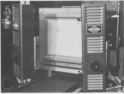
FIG. 3 Correct position of quartz lamps for back-lighting of copy-
board. Courtesy of nuArc Company, Incorporated.
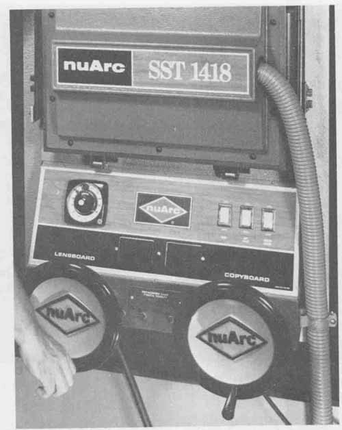
FIG. 4 Detail of the control console and adjustment control wheels.
(Courtesy of nuArc Company, Incorporated
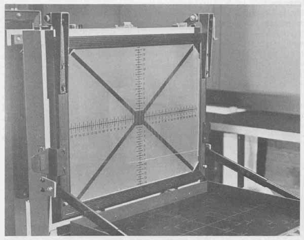
FIG. 5 Focusing plate positioned to inspect artwork image.
After the accuracy of the artwork reduction image has been verified, the focusing glass may be raised and locked into its vertical storage position above the film holder. The timer/focus switch should then be positioned to timer and the tape switch moved to off by depressing the bottoms of these rocker switches. In this mode, the exposure lamps will be off as well as the scale illumination lamps.
Proper film exposure is a function of the amount of light that strikes the film and the length of exposure time. The amount of light is set by the aperture opening within the lens system, the size of which is designated by f/stops. The maximum amount of light is transmitted through the lens using the widest aperture opening (lowest f/stop number.) The nuArc Model SST1418 camera has an f/stop range of f/10to f/22. It has been determined empirically that an aperture setting of f/16 will result in high-quality artwork phototools. This opening is set with the pointer using the upper scale shown in FIG. 6.
Exposure time is controlled by an electrical timer that is synchronized with the shutter mechanism of the lens. Refer again to FIG. 4. The timer pointer is set to the desired number of seconds of exposure and is activated by depressing the center button (see FIG. 7). Immediately, the lights are illuminated and the lens shutter is opened. The film is exposed for the preset time, at the end of which the timer activates the switching that turns off the lamps and closes the shutter. After each exposure, the timer will recycle to the preset position in preparation for another time exposure. With the optimum aperture opening of f/16, a timer setting of 10 seconds results in high-quality negatives ideally suited to pc artwork processing. A flow chart of the photographic reduction procedures using the nuArc SST1418 copy camera is shown in FIG. 8.
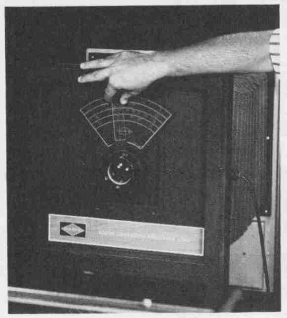
FIG. 6 Lens with diaphragm percentage control. (Courtesy of nuArc Company,
Incorporated.)
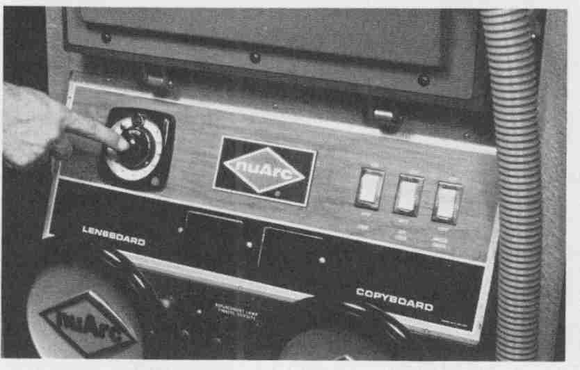
FIG. 7 Time of film exposure controlled with an electrical timer. (Courtesy
of nuArc Company, Incorporated.)
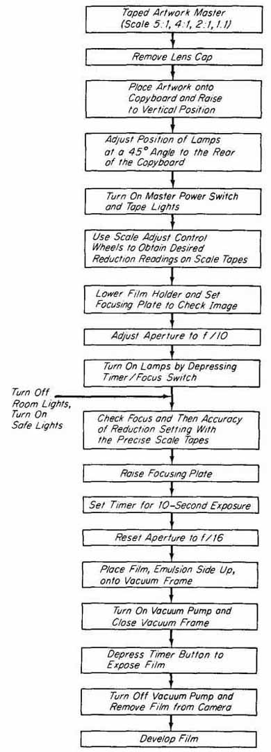
FIG. 8 Flow diagram for photographic reduction of artwork master.
2. EXPOSING AND PROCESSING PHOTOGRAPHIC FILM
The nuArc SST1418 copy camera or other similar unit used for reduction of artwork masters requires the use of suitable film. This film must possess high line contrast, reasonably fast processing time, and excellent dimensional stability. Several manufacturers have produced sheet film with these qualities, among them Kodak Kodalith Ortho Type 3 and Dupont Cronalith film. For purposes of illustration, the Kodak Ortho 3 film and its associated chemicals will be discussed. If other film is used, the specific manufacturer’s literature on film processing must be consulted.
The Kodak negative film is processed in the following sequence: exposure, develop, stop, fix, wash, and dry. Each of these steps will be described in detail.
To load the camera, a sheet of Kodak negative film is first removed from its light-tight box under safe-light conditions (Wratten 1-A or equivalent). Under normal lighting, this film would appear pale red but appears as light gray under the safe lamp. The emulsion side of the film (as opposed to the 0.004- inch-thick triacetate support backing side) is discernible by its lighter color. (If extremely high dimensional stability and durability are required, 0.007-inch film is available at slightly higher cost.) The film is centered onto the vacuum frame film holder so that its emulsion side is facing upward toward the opera tor. This is shown in FIG. 9. The vacuum pump is then turned on by a foot switch. With the vacuum holding the film firmly in place, the film holder is raised to its vertical position and latched. The artwork to be reduced is positioned on the copyboard so that it is centered over the translucent backing. An exposure step-table having 21 transparent-to-opaque sequential blocks is taped onto the artwork outside the corner brackets. With the setup in place, the glass cover is secured and the copyboard is raised to its vertical position. Before making the exposure, the operator should check the f/stop setting, timer setting, and reduction scale tapes as well as the position of the lamps.
The film is exposed by depressing the timer start button shown in FIG. 7. After exposure, the film is removed from the vacuum frame and is ready to be developed.
Kodak film is developed by the use of two concentrated chemicals:
Kodalith Liquid Developer Solution A, and Kodalith Liquid Developer Solution B. Since these chemicals are in liquid form, they require no special mixing equipment. For best results, they should be mixed with water which is at a temperature of between 65 and 70°F (18 to 21°C). (This water temperature is recommended for mixing all film baths.) The following five steps outline the preparation of the developer.
1. Determine the volume of developer required.
2. Divide this total in half to determine the amount of diluted developer A and diluted developer B required.
3. Divide this figure by 4 to find the amounts of both concentrates A and B needed.
4. Add three equal parts of water to concentrate A as determined in step 3; repeat for concentrate B.
5. Mix diluted A to diluted B to yield the total volume as determined in step 1.
The concentrates A and B are never added together. They must first be diluted before mixing.
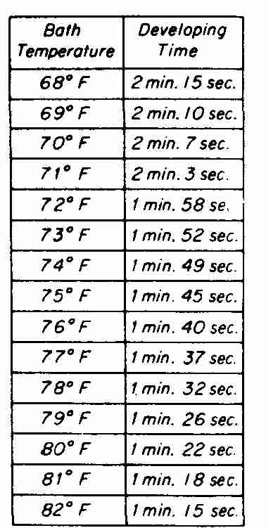
FIG. 10 Table of developing time as a function of bath temperature.
An example for the preparation of the developer will aid in understanding the various steps. In this example, it is required that 1 quart of Kodalith Developer be prepared. Following are the five steps just presented:
1. Total volume required—-1 quart (32 ounces).
2. Sub-volume—32/2 = 16 ounces of diluted A and 16 ounces of diluted B.
3. 16A/4 = 4 ounces of A concentrate; 16B/4 = 4 ounces of B concentrate.
4. Four times 3 = 12 ounces of water. Four ounces of A plus 12 ounces of water = 16 ounces of diluted A solution; 4 ounces of B plus 12 ounces of water = 16 ounces of diluted B solution.
5. Sixteen ounces of A diluted solution added to 16 ounces of B diluted solution yields 32 ounces (1 quart) of working developer.
The prepared solution is placed in a plastic developing tray. Under safe- light conditions, the exposed film with the emulsion side up is placed in the tray and constantly agitated until the film is developed completely. At a developing solution temperature of 68°F (20°C), the development time is between 2 and 2 minutes, the time decreasing as the temperature increases. At 74°F (23°C), the developing time is 1 to 2 minutes and at 80°F (27°C) reduces to 1 to 1 minutes.
A chart showing approximate developing time in minutes for specific bath temperatures is shown in FIG. 10. Proper developing time is critical. Depending upon how long the film is allowed to remain in the developing bath, it can result in it being under- or overdeveloped. An explanation of the developing process will aid in understanding the reason for paying close attention to the required time. When the film is initially exposed in the camera, certain portions remain under-exposed because the black conductor pattern on the copyboard absorbs light whereas the surrounding white area reflects light. As a result, the underexposed film portions form a latent image of the conductor pattern. When the film is developed, it yields a white conductor pattern image on a black background. During the developing process, the total emulsion surface is softened and feels oily to the touch. For this reason, extreme care needs to be exercised to avoid scratching this surface. Tithe film is allowed to remain in the developer for an excessive amount of time, the entire emulsion surface will become totally black. The film negative should be agitated in the developer solution long enough for a clear-cut image to appear with the desired contrast. Optimum contrast can be gauged by continual visual inspection of the device outline configuration. Attention should be focused on the smallest lead holes to be developed. When they appear as distinct sharp black dots, the developing process should be terminated immediately by quickly placing the film into a stop bath. TI lead holes are not present, continual comparison of the depth of color in the black areas of the developing film between both sides is made. As soon as both sides appear to have equal degrees of blackness, the film is ready to be placed into the stop bath.
Determining proper developing time by the methods just described is appropriate for experienced technicians. For the beginner, however, a more exacting method may be used. This method takes into account the light source and exposure time, lens setting and reduction scale, developing solution bath temperature, and time in the developing bath. It compensates automatically for any variations in these details to result in a correctly developed film. A Stouffer chart, is placed outside the corner brackets of the art work on the copyboard of the camera. As the developing process progresses, the blocks in the step table will begin to blacken, starting with the transparent block, step 1. By monitoring the step chart, the film is removed from the developing solution and placed into the bath at the point where the fourth step of the table has completely blackened with the fifth, and perhaps the sixth and seventh steps, partially blackened. This method of film developing assures consistent results regardless of any variations in the exposure setting. The appearance of a properly developed step table is shown in FIG. 11.
Whichever technique of film developing is employed, care should be exercised to avoid the possibility of under- or overdeveloping. Immediately after the film is properly developed, it is quickly placed into a stop bath. This stop bath is made up of 1 part of glacial acetic acid to 32 parts of water. To serve as an example of this mixture, to prepare 330 milliliters of stop bath, 10 milliliters of glacial acetic acid is mixed with 320 milliliters of water.
The developer is completely neutralized in the stop bath when the oily characteristics of the film emulsion no longer exist. This neutralization process will take approximately 1 minute. There is no visible change in the image. The negative is gently agitated in this stop bath for approximately 1 minute and then is placed in a tray containing Kodak Rapid Fixer (Solution A) with a hardener (Kodak Solution B bath for fixer) at 68°F (20°C) for approximately 1 to 2 minutes. The black areas of the film are insoluble in the fixer but the white emulsion of the conducting pattern image will dissolve in the solution. The negative must be agitated in the fixer solution for a sufficient period of time for all the emulsion in the conducting pattern area to be dissolved, exposing the underlying transparent backing. A black tray should be used because it permits the complete dissolving of the white emulsion to be more easily detected. The visual impression is a totally black film. The hardener is included in the fixer solution to stabilize the remaining emulsion.
To prepare 1 gallon of fixer bath, 1 quart of solution A is added to 2 quarts of water at 65 to 70°F (18 to 21°C). Three and one-half fluid ounces of solution B (hardener) are stirred into the solution. Finally, sufficient water is added to make the total solution equal to 1 gallon. The negative film of the tone control circuit being removed from the fixer solution is shown in FIG. 12.

FIG. 11 Properly developed 21-step table for Kodalith Ortho Type 3
film (settings: f/i 6, 10 seconds, 2:1 reduction).
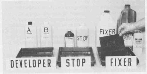
FIG. 12 Developing sequence for reduced negative.
After the fixing process, the film negative is washed in a spray of water at approximately 70°F (21 °C) for several minutes to remove all traces of the fixing solution ( FIG. 13). Once the film has been washed, it can be allowed to dry by simply suspending it with a clamp attached to an overhead line. This method is not recommended, however, since the surfaces of the negative tend to waterspot. To prevent this spotting a squeegee or photographic sponge may first be used to remove the excess water and then the negative should be al lowed to dry. The film is now completely processed into a negative of the printed circuit pattern. The negative should be handled carefully because it will scratch easily. Because of the involved nature of the photographic process, a flow diagram is provided in FIG. 14 to guide the technician through the individual steps. The completely processed negatives for the stereo system’s pre amplifier artwork master, solder mask, and marking mask are shown in FIG. 15.
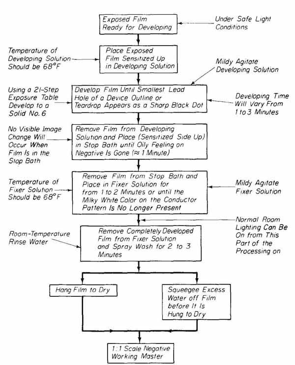
FIG. 14 Flow chart for developing negative film.
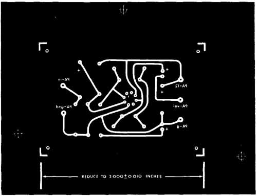
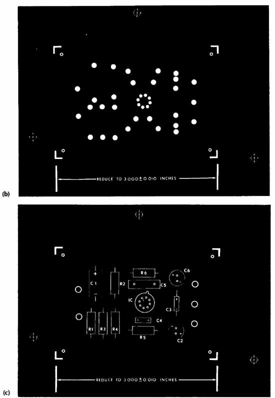
FIG. 15 Processed preamplifier negatives: (a) conductor pattern; (b)
solder mask; (c) marking mask.
3. CONTACT PRINTING
When the artwork masters have been photographically reduced into negative transparencies, the required 1 1 scale positives of the marking mask negatives can now be processed. If the film used in the initial reduction process yields a negative transparency, one more operation will generate the positive transparencies. To produce a positive from a reduced artwork negative is to in fact ob tam a positive transparency of the original artwork master that is reduced to the proper 1: 1 size scale for processing a pc board marking mask. (The process of converting a positive transparency of a marking mask into a silk screen.)
The processing of a 1: 1 scale positive from the same-size negative is best accomplished by contact printing using the same Kodak Kodalith Ortho Type 3 film used for the reduction of the original artworks. An arrangement showing the tone control circuit marking mask being contact-printed is shown in FIG. 16a. This system consists of a vacuum frame, pump, lamp and adjustable intensity, and exposure timer controls.
For contact printing, a sheet of Ortho 3 film is removed from its light- tight box under safe-light conditions. It is placed, emulsion side up, onto the black nonreflective mat in the vacuum frame. The reduced negative is then placed on top of the film and the glass cover of the vacuum frame is lowered and locked into place. The vacuum pump is switched on to maintain pressure of the negative against the film. Good contact is achieved when 25 in. Hg or greater is registered on the vacuum gauge. The contact printer lamp is positioned approximately 3 feet directly above the film to be exposed. For exposure, the intensity control of the light source is switched to intensity level 2 and the timer is set at 10 seconds. The start button is then depressed to activate the light and the timer.
After exposure, the vacuum pump is switched off and the film is removed from the frame. Still under safe-light conditions, the film is processed through the same developer, stop bath, fixer, and water rinse procedures as described in the preceding section. The flow diagram of FIG. 14 used to process negative film is also applicable for contact print processing. The negative used to make the contact print and the resulting developed positive are shown in FIG. 1 6b. With the completion of the photographic processes, the next phase in pc board fabrication will be to process the board into a functional circuit.
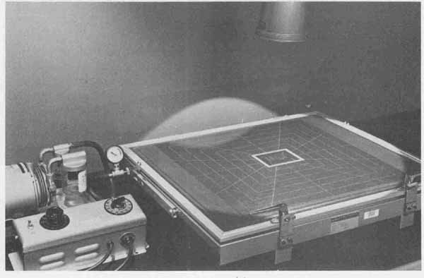
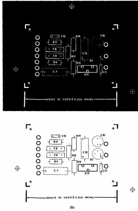
FIG. 16 Contact printing: (a) tone control negative and film being
exposed with contact printer; (b) negative and resulting positive tone
control marking mask films.
FIG. 16 (Cont.)
EXERCISES
A. Questions
1 What type of camera is recommended for photo-reducing artworks for printed circuits?
2 How should the step table be positioned on the copyboard with the art work?
3 Which of the following f/stops will allow the transmission of the least amount of light: 1/5.6,1/11, ff16, or ff22?
4 (a) What is the recommended temperature of the developing solution? (b) If the developing solution temperature is 78°F, what is the estimated time for developing exposed film?
5 Explain the term latent image.
6 Briefly describe the three methods for determining proper developing time.
7 What is the purpose of the stop bath in the developing process?
8 What areas of the developed film dissolve in the fixer solution?
9 How does the developed film, after contact printing, compare to the art work through which it was exposed?
10 Define the term phototool.
11 How are hot spots or reflections eliminated during film exposure?
12 What are the six processing steps for Kodak negative film?
13 What determines when the film should be removed from the fixer tray?
B. True or False
Circle T if the statement is true, or F if any part of the statement is false.
1 When producing a phototool, a 1: 1 scale image reversal occurs. T F
2 To obtain properly developed exposures, the step exposure table is placed over a clear area of the artwork inside the corner brackets. T F
3 Maximum contrast between light and dark areas of the art work results when back-lighting is used on the camera. T F
4 Under safe-light conditions, the emulsion side of Kodalith film appears lighter than the triacetate backing side. T F
5 Using an f/stop setting of 16, Kodalith film is exposed for 2 to 2 minutes. T F
6 The emulsion around the conductor pattern dissolves when the film is placed into the fixer bath. T F
7 A stop bath is used before the fixer bath to prevent overdeveloping. T F
8 When contact printing, the film to be exposed is placed in the vacuum frame with the emulsion side facing up. T F
9 Reversal of the image does not result when contact printing with Kodalith film as it does when photo-reducing on a camera. T F
C. Multiple Choice
Circle the correct answer for each statement.
1 Using a copy camera for artwork master reduction, a phototool can be produced to a tolerance of ( ±0.01, ± 0.002) inch.
2 Maximum contrast between light and dark areas of the artwork results with (front-, back-) lighting on the copy camera.
3 The recommended exposure setting for a copy camera is (1/16 at 10 seconds, f/8 at 30 seconds).
4 The emulsion side of film is placed facing (up, down) in the developing tray.
5 Developing time (is, is not) a function of developing solution tempera ture.
6 Neutralizing time in the stop bath is approximately (1 second 1 minute).
7 The exposed film becomes a transparency in the (fixer, stop) bath.
8 Contact printing is used to obtain 1:1 scale (negatives, positives) of the marking mask.
D. Matching Columns
Match each item in column A to the most appropriate item in column B.
COLUMN A 1. Fixer solution 2. Contact printing 3. Developing process 4. ff16 5. Emulsion side of film 6. Support backing of film 7. Stop bath |
COLUMN B a. Aperture opening b. 2 to 2 c. Glacial acetic acid d. 1 : 1 scale reversal e. Transparent film f. Lighter color g. Darker color |