AMAZON multi-meters discounts AMAZON oscilloscope discounts
5. FLASH PLATING: GENERAL INFORMATION
In the preceding section it was described how drilled pc boards were completely metalized with a thin ( 25 u-inches) deposit of electroless copper over all surfaces and the walls of each hole. These processed boards are allowed to remain in the 3% sulfuric acid solution in preparation of a copper flash plating which will build up the copper thickness to approximately 0.000125 inch (125 j This plating is required to prevent the electroless copper deposited on the hole walls from oxidizing which would result in voids, or nonconducting areas, after subsequent board processing.
Flash plating is accomplished in a plating tank containing a copper sulfate plating solution. The pc board is suspended in this solution and electrically connected to the negative side of a power supply. The positive side of the power supply is connected to a large copper anode which is also suspended in the plating solution. An electric current is passed through the plating tank causing copper ions from the plating solution to be attracted to the board and be deposited onto all copper surfaces. These copper ions are supplied to the plating solution by the corrosion of the copper anode. A thickness of 125 u-inches of copper can be electroplated by this method in a little more than 4 minutes. The result of flash plating is shown in FIG. 9. Note that the buildup of copper is continuous and uniform over the entire copper surfaces of the board in addition to the hole walls.

FIG. 9 Cross-sectional view of a double-sided, plated-through-hole
board after flash plating.
6. COPPER PLATING TANK AND PLATING ACCESSORIES
This section will describe the plating tank, plating rack, and the power supply for a typical prototype plating process. A rack for plating printed circuits holds either one or more boards in a fixed position in the plating solution. It must be capable of handling the large currents required in the plating process and not be easily affected by the plating solution. A basic plating tank setup is shown in FIG. 10a. The rack contacts the cathode work rod of the plating tank and is held securely with a wing nut or thumb screw. Tight contact between the thumb screw and cathode reduces resistance and holds the rack rigidly to the rod. The lower section of the rack connects to the copper foil of the pc board and is held firmly by another thumb screw or setscrew.
Plating racks are often fabricated from square copper rod stock, because this material is capable of handling 1000 amperes per square inch of cross-sectional area. A commercially fabricated plating rack capable of handling at least four boards at one time is shown in FIG. 10b. Because most of the rack assembly will be in contact with the plating solution, it is protected with a pestasol coating to prevent plating buildup. The contact points for the boards are fabricated of 300 series stainless steel. A smaller custom single board rack is shown in FIG. 10c. It is constructed of copper stock and stainless steel screws. Subsequent discussions on plating will make use of this rack.
Because the copper will be electroplated from a sulfate plating solution, the recommended material for the tank is stress-relieved polypropylene or poly ethylene plastic.
A tank size of 12 inches long by 12 inches wide by 12 inches deep will be adequate for most prototype work. This tank will have a solution capacity of approximately 6 gallons (22.7 liters) when the plating solution is 9.75 inches from the bottom. The exact volume can be calculated by dividing the number of cubic inches of solution by 231 cubic inches per gallon. The following example will demonstrate this calculation.
Example: Determine the exact volume of plating solution for a 12 inches by 12 inches by 12 inches tank.
Volume of solution (cubic inches) = length x width x depth of solution
= 12 inches x 12 inches x 9.75 inches
= 1404 cubic inches
Solution volume (gallons) = volume of solution (cubic inches)/231 cubic inches/gallon
= 1404 cubic inches/ 6.08 gallons = 231 cubic inches/gal
A 12-inch-deep tank with approximately 10 inches of plating solution (2 inches of clearance to the rim of the tank) will allow the insertion of the anodes and the racked pc board to be plated without causing the solution to spill over the top of the tank.
The tank is fitted with two anode work rods and one cathode work rod. These rods are made of g-inch-diameter solid copper rod stock. This diameter will easily support the weight of the copper anodes and the plating rack with pc boards as well as handle the large currents used in the plating process. The work rods are held securely in position with pairs of Lucite or plastic blocks fastened onto opposite ends of the tank rim. The anode work rods are positioned over the tank parallel to one another and 1 inch inward from the sides of the tank. The cathode work rod is positioned parallel to the anode rods and centered between them. The on-center spacing between either anode work rod and the cathode work rod is 5 inches (see FIG. 10a). These distances must remain constant between the surfaces of the board and the anodes for proper plating.
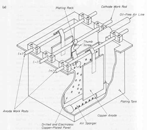
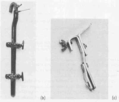
FIG. 10 Plating tank and accessories for electrolytic copper plating:
(a) prototype copper plating tank; (b) commercial plating rack; (c) custom
single-board rack.
In order to result in uniform plating, effective solution movement through the holes in the board is required. The amount of time required to electroplate a given thickness of copper can be reduced with more vigorous solution movement. To accomplish this, an air agitation system is built into the plating tank (see FIG. 10a). The source of air should be an oil-free low-pressure blower delivering approximately 1.5 to 2 cubic feet per minute of air for each square foot of plating tank surface area. The air is conveyed to the plating solution through a 0.5-inch PVC sparger system. Note in FIG. 10a that the sparger pipe is positioned directly below the pc board to be plated. A series of 1/16-inch-diameter holes are drilled into the bottom of the sparger pipe at 45-degree angles to its centerline. The sparger is positioned approximately 1 inch above the bottom of the tank. Air entering the pipe exits through these small holes and is deflected off the bottom of the tank. The upward motion of these expanding air bubbles causes vigorous solution movement across the outside surfaces of the board as well as through all the drilled holes.
The negative terminal of a plating power supply is electrically connected to the cathode work rod. Both anode work rods are electrically connected together (anode strap) and then connected to the positive terminal of the power supply. See FIG. 11. All electrical connections should be made with AWG No. 12 stranded wire protected with a chemical-resistant plastic insulation.
The plating power supply should have the following characteristics:
1. Continuous adjustment of output voltage from 0 to 6 volts dc.
2. Current capacity in excess of plating current requirements (a maximum of 15 amperes is acceptable for the plating tank illustrated).
3. Percent ripple at full load current should be equal to or less than 5%.
4. A meter to monitor the dc output voltage at the + and — terminals.
5. A meter to monitor the load current.
The circuit schematic for a typical plating power supply is shown in FIG. 12.
The types of material used for the anode, together with its shape and surface area, will effect the quality of the resulting plating onto the pc board surface. Only phosphorized copper anodes should be used since they will corrode properly in an acid copper-plating solution. They should contain 0.04 to 0.06% phosphorus by weight. Copper anodes designated as OHFC or pure copper anodes should not be used.
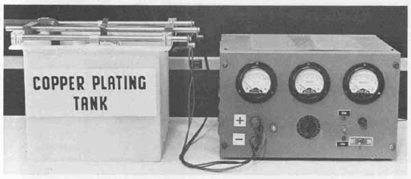
FIG. 11 Typical prototype copper plating setup.

FIG. 12 Schematic diagram of plating power supply.
Anodes are available in various shapes and in a wide range of sizes ( FIG. 13). The standard shapes are flat, oval, round, sawtooth, and gear tooth. A flat anode is preferable in a small plating tank since it results in more uniform current density. The oval, sawtooth, and other special shapes are designed to increase the surface area of the anode. The criteria for selecting an anode is its surface area relative to the area of pc board to be plated. For the plating of copper, an anode-to-cathode surface area ratio of approximately 1:1 is recommended. This means that the surface area of the anode facing the pc board in the plating tank should have a surface area approximately equal to the one side of the pc board that it is facing. Uniform plating through the holes of double- sided pc boards will result if the overall exposed copper path area is equal on both sides of the pc board. Double-sided plating is accomplished with the use of two anodes, one positioned on each side of the pc board, both having identical surface areas. This will simplify and optimize the plating process.

FIG. 13 Standard anode shapes.
The anodes must be provided with a hook whose length will allow the anode to extend from the anode work rod down into the plating solution yet allow the top of the anode to protrude slightly above ( inch) the surface of the solution. The length of the anode should be such that it does not extend below the bottom of the pc board more than 1 inch.
To illustrate the calculation of the correct size of an anode for a specific application, we will use the preamplifier layout discussed in Section 16, which will be processed into a 5- by 5-inch card. The area of copper which will be exposed to the plating solution is determined by multiplying the length (L) of the board by its width (W). This will yield the overall area in square inches of exposed copper surface for one side. For the preamplifier layout, this results in 5 inches by 5 inches, or 25 square inches. This figure is used to determine the anode area required for plating as well as the plating power supply current density (Sec. 8) to obtain optimum plating.
There are two restrictions involved in the selection of the anode size required for plating. These are: (1) its surface area must approximately equal that of the cathode, and (2) it cannot extend more than 1 inch below the pc board. Selecting an anode whose length is 6 inches (1 inch longer than the board) will satisfy the length criterion. From the range of standard available widths, a 5- inch-wide anode will result in an area of 30 square inches which is slightly larger than that of the cathode (25 square inches). Since each side of the pc board has equal areas, two 5- by 6-inch anodes will meet all of the requirements for flash plating the preamplifier board even though the ratio of anode area to work area is slightly larger than the optimum 1:1 proportion.
Prior to the placement of the anodes into the plating tank, proper procedures must be followed to avoid contaminating the plating solution. All plating solutions are extremely susceptible to organic contamination. For this reason, the anodes must be properly cleaned and correctly bagged. Anode degreasing is accomplished by scrubbing the surface with a brass bristle brush and cold tap water. The anode is then rinsed thoroughly and dipped into a 10% by volume solution of sulfuric acid for approximately 10 minutes. After this acid dip, the anode is ready to be bagged.
The anode bags used should be made of dacron or polypropylene (never cotton) and should be 2 inches wider and 2 inches longer than the anode. The bag must be leached (purified) of all sizing or organic contaminations that it was exposed to in its manufacturing process. Leaching is accomplished in three steps. First, the bag is boiled in water for at least 1 hour. It is then removed from the boiling water and rinsed in cold water. Finally, the bag is soaked for 24 hours in a % by volume of Copper Gleam PC solution (see Sec. 7). One gallon of this solution will be sufficient for two bags of the size described. To mix 1 gallon of this solution, 190 milliliters of Copper Gleam PC is added to 3594 milliliters of water. The treated bags are then tied around the cleaned anodes. This is shown in FIG. 14a. The anodes are now ready to be installed into the plating tank ( FIG. 14b) which, together with all the hardware and plumbing, must be thoroughly leached prior to adding the plating solution and the an odes. The leaching process is the same as that described in Sec. 3 for the electroless copper deposition line. Again, leaching is required only when the plating solution is added for the first time. Recall that detailed information for leaching is given in Appendix XII and should be reviewed before proceeding to the next section.
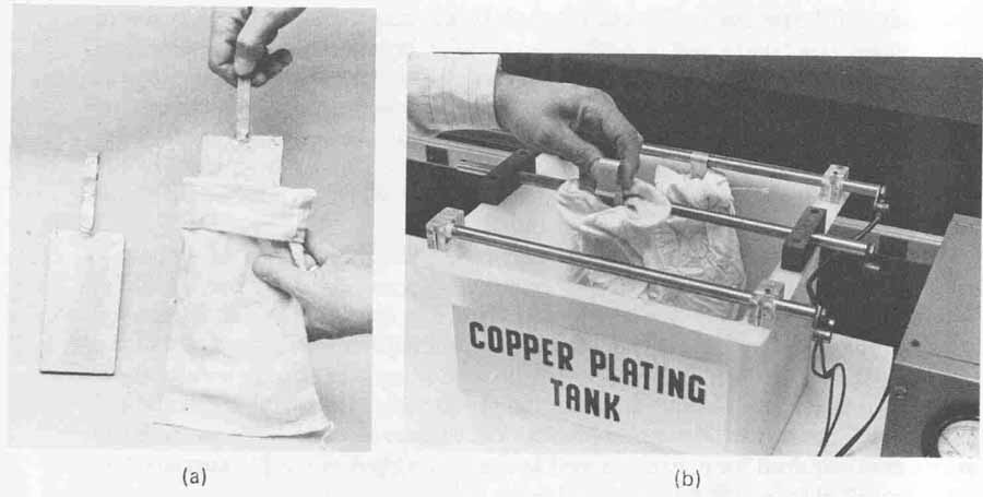
FIG. 14 Anode bag preparation: (a) anode and leached anode bag; (b)anode
installation into copper plating tank.
7. COPPER SULFATE PLATING SOLUTION
After the plating tank and the accessories have been leached, the plating solution is prepared. For our purposes we have selected a copper sulfate solution since it requires only one principal additive and is thus easy to control. A key ingredient in this plating bath is manufactured by the Lea Ronal Company and is sold with the trade name of Copper Gleam PC. The use of this solution results in a bright copper deposit which is ideally suited for plating pc boards.
The copper sulfate plating solution is made up of the following:
1. Copper sulfate pentahydrate liquid
2. Sulfuric acid (reagent grade)
3. Hydrochloric acid (reagent grade)
4. Copper Gleam PC additive/brightener
5. Distilled water
Highly pure copper sulfate provides the source of copper in the plating solution. The most convenient use of this chemical is in liquid form. Sulfuric acid is added to the solution to improve its conductivity and also aids in anode corrosion. Reagent-grade sulfuric acid is used to prevent contamination from entering the plating cell. A small amount of hydrochloric acid is added since chlorides aid in brightening the plating. The Copper Gleam PC provides a bright ductile copper deposit over the entire board surface. The formulation of 10 gallons of Copper Gleam PC copper sulfate plating solution is given in TABLE 1, which shows the required amount of each ingredient and the order of mixing.
To prepare a plating bath for the 6-gallon tank described previously, TABLE 2 lists the ingredients and order of mixing. The amounts of each ingredient were derived by simply taking of those amounts listed in TABLE 1. The 6-gallon bath is prepared by first placing 3.72 gallons (14.08 liters) of distilled water into the leached tank. Next, 1.68 gallons (6.36 liters) of liquid cop per sulfate pentahydrate, having a copper concentration of 2.25 pounds of copper per gallon, is added to the water. The solution is stirred slowly until it is thoroughly mixed. The 0.6 gallon (2.27 liters) of sulfuric acid is then added, stirred, and the solution is allowed to cool to room temperature. Finally, 2.7 milliliters of hydrochloric acid and 0.03 gallon (114 milliliters) of Copper Gleam PC are added and the solution thoroughly mixed. The height of the solution should be marked on the outside of the tank to note any decrease in level due to evaporation. Any significant decrease of solution should be replaced so as to return it to the original level in the tank. The bath should be maintained at room temperature and loosely covered with sheet plastic when not in use to protect the solution from dust and other foreign matter.

TABLE 1 Formulation of 10 Gallons of Copper Plating Solution with Copper
Gleam PC Brightener
All plating solutions require periodic chemical analysis. The techniques of chemical analysis for the type of bath just described are beyond the scope of this book. However, since the amount of solution described in TABLE 2 is relatively small and not significantly expensive, the entire bath should be re placed if plating problems are encountered. A fresh batch of solution can be used successfully for a reasonable length of time if extreme care is exercised to minimize the introduction of organic contaminations into the bath. Detailed chemical analysis procedures for the bath described may be obtained from the Lea Ronal Company.
Before pc boards can be plated, the anodes must be conditioned (electrolyzed) after they have been cleaned, bagged, and hung into the plating bath. The conditioning process causes a film to be formed on the anodes and involves simply hanging sample copper-clad panels from the cathode rod into the plating solution. The power supply is adjusted to a value that will result in a current density of 10 amperes per square foot of surface area on the sample panels used. A suitable anode film is formed in approximately 4 hours.

TABLE 2 Formulation of 6 Gallons of Copper Plating Solution with Copper
Gleam PC Brightener
8. COPPER SULFATE FLASH PLATING
With the pc boards which have been processed through the electroless deposition line stored in the 3% sulfuric acid holding tank and the plating tank fully prepared, the flash plating process can begin. The air supply is turned on and the rack of boards is removed from the holding tank. They are immediately placed into a rack, such as the ones shown in FIG. 10, and are ready for the electroplating process. The power supply is turned on and set just slightly above its zero reading. The racked boards are placed into the plating solution and swished back and forth for 15 seconds before electrical connection is made to the cathode rod. This 15-second dip will remove any minor oxides which may have formed, thereby reactivating the surfaces for electroplating. The rack holding the pc board is then lowered and hooked onto the cathode rod and se cured with the thumb screw (refer to FIG. 10a).
The current density recommended by the manufacturer for flash plating is 30 amperes per square foot ( 208 milliamperes per square inch) of pc board surface. However, it is important to note that this high-current density initially subjected to the 20 pinches of electroless copper deposited on the hole walls would cause its destruction. It is therefore essential that the plating process begin by applying one-fifth the recommended current density, that is, 6 amperes per square foot ( 42 milliamperes per square inch), for 2 minutes and then an additional 4 minutes at the recommended rate of 30 amperes per square foot.
The power supply is to deliver 30 amperes of current for every square foot of copper that is exposed to the plating solution. In Sec. 6 it was determined that the preamplifier panel has a surface area of 25 square inches. Since this is a double-sided board, the total surface area exposed to the plating solution is twice this amount or 50 square inches. We will now calculate the amount of current that the power supply is to deliver for the first 2 minutes (i.e., at one- fifth the recommended rate of 208 milliamperes per square inch) as follows:
initial current setting
= recommended current density x total surface area (1 \ 208 milliamperes
= — } . x 50 square inches
5 square inch
2080 milliamperes ( 2 amperes)
When the power supply is set at 2 amperes, you will note that the output voltage is low (<1 volt).
After 2 minutes at the 2-ampere rate, the power supply should be readjusted for the recommended current density for an additional 4 minutes. The final current setting is calculated as follows:
final current setting
= recommended current density x total surface area
208 milliamperes / square inch x 50 square inches
= 10,400 milliamperes
= 10.4 amperes. (= 10 amperes)
Recall that the power supply, specified in Sec. 6, has a current capacity of 15 amperes, which is well in excess of the requirements of our plating application.
Thickness of the copper plated onto the surface of the pc board is dependent upon (1) the current density and (2) the plating time. For the copper sulfate bath operated at 30 amperes per square foot, copper is deposited at the rate of 100 1 every 3 to 4 minutes. To result in a thickness of 125 ranches, the required plating time would be slightly more than 4 minutes.
After the flash plating process has been completed, the power supply is turned off and the rack is loosened from the cathode work rod and immediately removed from the tank. The pc board is then thoroughly rinsed in cold tap water for at least 1 minute and then dried. Inspection of the plating should re veal a smooth and bright deposit of copper on all surfaces, including the walls of all the drilled holes.
The next phase in the processing of the pc board is to photosensitize both of its sides so that the conductor patterns may be imaged. Section 18 presents the procedures for photosensitizing and imaging in preparation for the final processing steps discussed in Section 19.
EXERCISES
A. Questions
1 The formula:
gallons = LxWxH/231
is used to calculate the capacity, in gallons, for rectangular-shaped tanks where L, W, and H are in inches. Calculate the capacity of tanks having the following dimensions in inches:
2 Calculate the amount of rinse water required in gallons per hour for a
12- by 18- by 36-inch rinse tank with a turnover rate of six times per hour.
3 Explain the function and determine the makeup of a 20-gallon ammonium persulfate bath.
4 Discuss the function and solve for the makeup of a 60-gallon bath of Catalyst 9F.
5 Describe the function and calculate the makeup of an Accelerator 19 bath for a 6- by 30- by 60-inch tank.
6 Give the function and determine the makeup of a 328Q bath for an 8-by 16- by 36-inch tank.
7 Using the graph of time versus percent copper concentration shown in FIG. 6, determine the plating time required at 75°F. Next using the graph of time versus bath temperature, find the plating time required with a bath having an 80% copper concentration.
8 Determine the resistance in ohms for a conductivity reading of 2500 uS/cm using the formula:
1 / conductivity
9 Calculate the anode size for copper plating a 6- by 9-inch double-sided pc board.
10 What plating bag size should be used for a 4-by 20-inch copper anode?
11 Discuss the function and solve for the makeup of a 35-gallon copper sulfate plating bath using Copper Gleam PC as the brightener.
12 Determine the initial power supply setting for current and then the recommended current density for a 7- by 12-inch double-sided pc board for copper flash plating.
13 What is a plated-through hole?
14 What is the purpose of electroless copper deposition?
15 How are anode bags leached, and for what purpose?
B. True or False
Circle T if the statement is true, or F is any part of the statement is false.
1 When drilling stacks of pc boards on CNC machines, a thin entry sheet of aluminum is placed on top of the stack. T F
2 The PTH process requires that pc boards be drilled after the electroless copper deposition and copper flash plating processes are completed. T F
3 The electroless copper deposition process will deposit a layer of copper approximately 20 to 30 thousandths of an inch thick on board surfaces. T F
4 Catalyst 9F is used to seed particles of palladium onto the surfaces of hole walls to provide a site for copper deposition. T F
5 Air spargers are used in rinse tanks to improve the efficiency of rinsing pc boards. T F
6 Flash plating is used to prevent deposited electroless copper from oxidizing. T F
7 For copper plating, the surface area of the anode must be approximately equal to that of the cathode. T F
8 The current density for flash plating is 30 amperes per square inch of pc board surface. T F
9 Anode bags should be made of cotton. T F
10 All heaters, plumbing, and spargers used with a copper deposition line should be leached at the same time prior to the startup use of the line. T F
Multiple Choice
Circle the correct answer for each statement.
1 CNC multi-panel drilling uses (aluminum, XP hardboard) as entry material and (aluminum, XP hard board) as bottom backup material.
2 The electroless copper deposition process is performed (before, after) the drilling operation.
3 The air spargers installed in each of the rinsing bays of the electroless copper deposition line (increase, decrease) the volume of water used.
4 The electroless copper deposition line uses eight water rinse cycles which require the water to be maintained at a temperature of (70°F, 150°F).
5 Palladium is seeded onto the insulated material of the pc board in the (Accelerator 19, Catalyst 9F) bath.
6 Approximately 25 1 of copper is deposited on an activated surface in the (Catalyst 9F, Cuposit 328Q) bath of the electroless deposition line.
7 The holding tank for board storage after the copper deposition process contains a (3%, 30%) concentration of sulfuric acid.
8 The purpose of copper sulfate in the electrolytic flash plating tank is to (improve conductivity, provide a source of ions).
D. Matching Columns
Match each item in column A to the most appropriate item in column B.
COLUMN A | COLUMN B
1. 3% sulfuric acid 2. CNC drill/router 3. Catalyst 9F 4. Copper anodes 5. Electroless copper deposition 6. Current density 7. Ammonium persulfate 8. Flash plating |
a. 30 A/ft/^2 b. Seeding c. Microetch d. Positive terminal e. Storage bath f. 125 u-inches of copper g. 400 hits/minute h. 25 u-inches of copper |