AMAZON multi-meters discounts AMAZON oscilloscope discounts
LEARNING OBJECTIVES:
Upon completion of this Section on double-sided printed circuit board copper deposition and flash plating, the student should be able to:
1. Stack and shear pc boards to their correct size.
2. Understand the major components and performance characteristics of production CNC drill/router machines.
3. Understand the equipment and processes involved in an electroless copper deposition line.
4. Leach all tanks and accessories in an electroless copper deposition line.
5. Properly mix, maintain, and control all the solutions of the electroless cop per deposition line.
6. Successfully operate an electroless copper deposition line.
7. Understand the equipment and processes involved in copper flash plating.
8. Properly mix, maintain, and control the solution of the flash plating bath.
9. Flash-plate copper onto pc boards.
0. INTRODUCTION
In Section 16 a number of design requirements for the generation of artwork suitable for double-sided pc boards was presented. Recall that major emphasis was placed upon electrically interconnecting circuitry on the component side of the board to that on the circuit side. For prototype applications, where only a few boards of any specific type are processed, this side-to-side interconnection may be accomplished by first dip- or wave-soldering the processed board on the circuit side and then hand-soldering the leads on the component side to its circuitry. Although this method is time-consuming, it is adequate for obtaining the desired results.
Volume production manufacturing requires that side-to-side interconnections be made an integral part of the pc board in the fabrication process. This interconnection technique, adopted by high-volume pc board manufacturers, is the plated-through-hole (PTH) process, which lends itself to mass-production applications and results in a much higher degree of finished board control. Be cause it is an extensive multi-stepped process, the discussion of double-sided plated-through-hole pc board fabrication will extend into the following three Sections. The following Section descriptions will provide an overview of this complex process.
This Section begins with a detailed discussion of shearing pc board stock to size and then drilling all of the required holes. Through a series of chemical baths, a very thin layer of copper is then deposited electrolessly over the entire board surface covering all exposed areas, including the edges and the walls of the drilled holes. This layer of copper results in the initial electrical interconnection between the copper foil on both sides of the board through the plating of the walls of each drilled hole. To increase the thickness of the copper deposited on the walls of the holes, the board is further treated in a copper flash plating process, which is a standard electrolytic method employing a copper plating bath and electric current.
In Section 18 the fabrication process continues with the application of dry-film photo-resist to image the copper foil on both sides of the board with the desired conductor patterns. (Double-sided conductor pattern artwork is presented in Section 16.) The board is completed in Section 19 by first addition ally electroplating the exposed conductor pattern and hole walls with copper followed by a solder electroplating process. This solder plate serves as the etching resist and ensures a highly solderable pc board. After all of the plating is completed, the dry-film resist is stripped from the board followed by etching, reflowing, and finally routing to size.
As can be seen from this introduction, the fabrication of a double-sided plated-through-hole pc board requires many sequential processes, some of which demand exacting procedures. For this reason, each of the processes are described in detail.
1. ELECTROLESS COPPER DEPOSITION: GENERAL INFORMATION
The discussion of double-sided plated-through-hole fabrication begins with the selection of the appropriate pc board stock. For our purposes, we have selected grade FR-4 double-sided board stock having a thickness of 0.059 inch and a copper thickness of 1 ounce per square foot (oz/ft on each side. This thickness is most often specified, although thinner copper thicknesses are becoming more popular for fine-line applications (i.e., less than 10-mil path widths and spaces). The stock is first sheared into the correct panel size to accommodate the required conductor pattern artwork.
Two precisely located tooling holes are then punched into each panel as well as into a layer of backup material and entry material. All these layers are then stacked and pinned together for drilling. A pinned lay-up of panels for drilling is shown in FIG. 1. The bottom backup panel is a piece of i-in XP hardboard material. Three double-sided copper clad pc boards are shown stacked on top of the bottom panel. The top drill-entry material is a thin sheet of aluminum. The purposes of the entry and backup panels are to (1) prevent burring of the drilled holes, (2) clean and cool the drill bit to prevent tearing hole walls, and (3) protect the underlying surface of the drilling machine worktable. The layers are held firmly together with steel stacking pins especially made for this purpose. The pins are pressed into the previously drilled tooling holes.
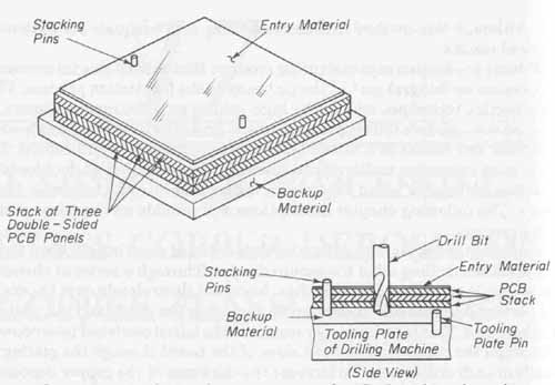
FIG. 1 Stacking and pinning setup used on CNC machines for multi-panel
drilling.
A typical multispindle CNC (computer numerical control) drilling ma chine, used to automatically drill separate stacks of panels simultaneously, is shown in FIG. 2. These machines are also used to route individual pc boards to size and shape. The major components of a CNC drill-router machine are (1) computer controller; (2) granite slab base; (3) moving worktable, servomotor drive, and feedback system; and (4) directly programmable 15,000- to 80,000 rpm spindles. The massive base is required to resist the immense inertial forces of the rapidly moving worktable as well as to support the entire machine structure.
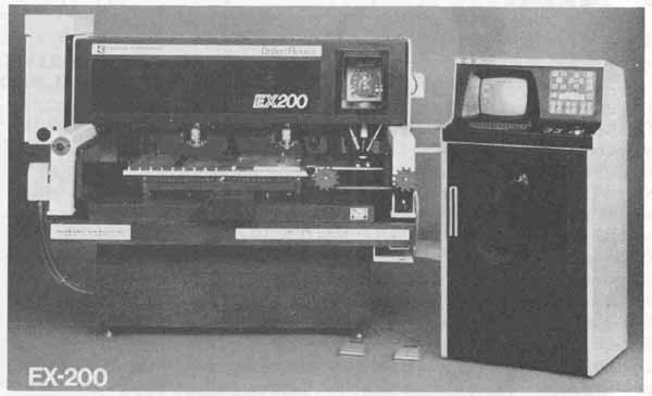
FIG. 2 Automatic driller/router machine. Courtesy of Excellon Automation,
Division of Excellon Industries, an Esterline Company.
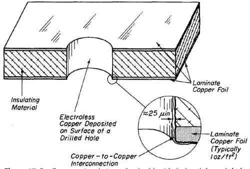
FIG. 3 Cross-sectional view of a double-sided plated-through-hole board
after copper deposition.
Typical drilling performance characteristics of CNC drilling machines are (1) x and y table positional speeds of up to 500 inches per minute, (2) positioning accuracies of ±0.0002 inch with repeatability of ±0.0001 inch, (3) drill hole ac curacy of ±0.001 inch, (4) production speeds of 400 “hits” (drilled holes per minute, and (5) automatic drill size changes in 10 seconds. The CNC machine is programmed to drill multi-board panels in a step-and-repeat mode and to take optimum paths between holes to further reduce drilling time.
After the boards have been drilled, they are unstacked and mechanically deburred on both sides using 400-grit sand paper. These boards are now ready for the elecroless copper deposition process. This process will deposit a layer of copper approximately 20 to 30 millionths of an inch thick on all board surfaces, that is, the copper foil on both sides, the board edges, and most important, around the inner glass/epoxy surface of each drilled hole. To accomplish this, the drilled boards are first secured in specially designed racks and then processed through 16 chemical baths and water rinses. In this plating line, the chemical makeup of baths, the solution temperatures, the immersion time rate of board agitation, the air agitation of solution, and the quality of water rinses are rigidly controlled. After the boards have been processed through the 16- bath copper deposition line, they will exhibit a slightly brownish copper appearance throughout, that is, on the copper foil surfaces, the edges, and walls of the drilled holes. A cross-sectional view of a board after it has been processed with the copper deposition baths in shown in FIG. 3.
2. ELECTROLESS COPPER DEPOSITION LINE: MECHANICAL CONSIDERATIONS
A typical electroless copper deposition line is shown in FIG. 4a. It consists of 16 stations, or bays, all of which are the same size. In the line shown, each bay is designed to accommodate a 10-gallon (37.85-liter) bath. Thus their physical dimensions are approximately 6 inches wide, 24 inches deep, and 24 inches high. The bays are constructed of a welded rigid plastic material such as stress- relieved polypropylene with PVC plumbing. Each bay is fitted with a PVC ballcock drain valve leading into a central drain manifold to facilitate solution removal. A high-torque low-rpm motor is mounted to the left side of the deposition line. The motor is coupled through a cam and a 1-inch-square fiberglass drive bar to a pair of 1-inch-square rails. These rails are positioned on Teflon guides and run the length of the line along the top outside edges. The racked boards are lowered into each of the baths with the arms of the rack resting on the rails. A typical rack is shown in FIG. 4b. The motor-driven rails provide a transverse motion of the racked boards which forces the solution through the holes as the boards travel back and forth in the baths. The rate of travel should be relatively slow, not to exceed 12 complete cycles per minute with a 2- to 4- inch stroke cycle.

FIG. 4 Standard 16-bay electroless copper deposition line: (a) detailed
front sectional view; (b) 316 stainless steel rack for copper deposition.
The deposition line can be divided into two major bay groupings which are (1) water rinse stations and (2) chemical treatment stations. There are eight of each of these groupings in the line. Refer to the deposition line shown in FIG. 4a. The first bay on the left is the only one required to be operated above room temperature. It is fitted with a 1000-watt stainless steel heater which is sufficient to raise the temperature of 10 gallons of solution to the required 150°F (66 °C) in a reasonable amount of time. A temperature control with a probe is used to maintain this temperature and prevent overheating of the solution. Bay 14 in FIG. 4a is the electroless copper bath and is fitted with a length of PVC tubing connected to an aquarium pump. The tubing extends to the bottom of the bay. The bubbles generated from the pump aid in stabilizing the electroless copper solution.
Each of the rinse stations is equipped with an overflow drain near the top rim of the bay. This is shown in FIG. 4a. Rinse water is supplied from a mixing valve which regulates the temperature to a central manifold water system (PVC) that feeds each rinse station. From this system, a PVC water pipe is routed through the rear wall of each rinse bay, down the back of the tank, and runs along the bottom center of the tank. Several small equally spaced holes are drilled into the bottom section of the pipe. In this way, clean water enters continuously from the bottom of the tank and moves upward, finally leaving the bay through the drain at the top. This results in contaminants, which are generated from rinsing the racked boards, being forced upward and out into the drain. For optimum results, the rinse-water temperature should be maintained between 60 and 70°F (16 and 21°C). Sufficient volume of water to have a bath turnover of from 5 to 10 times the capacity of the tank per hour should be sup plied. This will maintain the level of rinse-water contamination, even for a constantly working line, within acceptable limits. For the relatively small deposition line shown in FIG. 4a, which has eight 10-gallon rinse bays, a turn over of 10 times per hour for each bay would require a water supply of 800 gallons per hour.
To reduce the large volume of water required and to result in more effective board rinsings than that provided by rack movement alone, a PVC air sparger is installed in each of the rinse stations. These diameter pipes are L-shaped and enter the top of the bay through a hole at the rear of the tanks. They run downward and along the bottom of the tanks. Each sparger has equally spaced holes drilled along the bottom of its total horizontal length. This pipe is returned to a central manifold which in turn is connected to an oil- and dust-free blower system equipped with airflow control valves. Air entering each rinse bay at the rate of 1 to 2 cubic feet per minute for each square foot of tank surface will result in greatly increasing the solution movement. This provides more effective rinsing with minimum water input required.
The rack used with the copper deposition line is made from 316-type stain less steel and is designed so that it will rinse freely and entrap no chemicals.
The rack shown in FIG. 4b has a two-tier arrangement of slotted spacers. The slots are approximately inch apart, inch deep and 20 thousandths of an inch wider than the thickness of the pc boards to be processed. Boards mounted onto the rack are therefore slightly off vertical, which results in good solution- to-hole movement and more effective rinsing. The rack is fitted with front and back extensions so that it may be positioned onto the work rod agitator.
In this section we have described the mechanical aspects of a typical low- production hand-operated deposition line common to many printed circuit fabrication shops. To aid in efficiency, several improvements can be made to this basic line. For example, the addition of a hoist to raise and lower the rack into the baths would increase productivity. Also, the installation of conductivity meters in the rinse stations to monitor the level of contamination would reduce production time by sounding an alarm when levels of contamination exceed preset limits.
In the next section we describe the procedures for starting up a new deposition line and also the chemical baths involved in the copper deposition process.
3. ELECTROLESS COPPER DEPOSITION: CHEMICAL PROCESSES
After the construction of a new copper deposition line, all bays, racks, and hard ware must be thoroughly leached (chemically cleaned) to remove all contaminants prior to filling any of the tanks with chemical baths or rinse water. All heaters, plumbing, and spargers should be installed so that they may be leached at the same time. The leaching process is required only for startup purposes, that is, before the chemicals are added to the tanks for the first time. A detailed leaching process is given in Appendix XII. The student should refer to this appendix before proceeding to the next section. It should be emphasized that even though a new tank may look clean, it is probably the single largest source of bath contaminations. Those contaminations, such as mold release film, are typically the cause of many copper deposition failures. For this reason it is absolutely essential that all parts which will come into contact with any of the chemical baths be properly leached.
The basic 16-bay deposition line as described in Sec. 2 and shown in FIG. 4a, can be divided into three major categories, described by the functions of each bath. Viewing the line from left to right, these categories are (1) bays 1 through 7 are for cleaning, (2) bays 8 through 13 are for activating, and (3) bays 14 through 16 are for copper deposition and holding (see Fig. 5). During the cleaning cycle, the copper surfaces of the pc board as well as the hole walls and board edges are cleaned and conditioned to accept activation and subsequent copper deposition. The activation process “seeds” (deposits) particles of precious metal (palladium) onto the surfaces of the nonconductive hole walls in order to provide a site for subsequent copper deposition. In the copper deposition process, these sites are deposited with 20 to 30 millionths of an inch (20 to 30 pinches) of copper resulting in a completely metalized board capable of being flash electroplated with copper (Sec. 5) to a thickness of approximately 0.000125 inch (125 u-inches).
To describe the complete deposition process in detail, a standard low- speed electroless copper process developed by the Shipley Company, Inc. is shown in flow-chart form in FIG. 5 and it will be discussed in detail. This is called the Cuposit 328Q process and it will be described using the 16-bay deposition line discussed in Sec. 2 and shown in FIG. 4a. Recall that each of the bays has a capacity of 10 gallons.
As shown in FIG. 5, the boards are first racked in accordance with the discussion of Sec. 2. Remember that during this entire process, the rails sup porting the plating rack are driven back and forth to ensure the proper movement of solution through the holes in the board.
Each of the baths shown in FIG. 5 will now be described:
Bay 1: Cleaner/Conditioner 1175A. This is a strongly alkaline bath de signed to (1) clean oils, stains, and oxides from the copper surfaces, and (2) condition the glass/cloth hole wall surface to accept the activation (seeding) layer. This 2.5% by volume bath is prepared by adding 0.25 gallon (946 milliliters) of 1175A concentrate to 9.75 gallons (36.9 liters) of tap water to result in 10 gallons of working solution. With the bath maintained at an operating tempera ture of 150°F to a maximum of 180°F (66 to 82°C), the racked boards are loaded into the solution for 3 to 5 minutes.

FIG. 5 Flow chart depicting the Shipley copper deposition 328Q process.
Bay 2: Water Rinse. The rack is removed from bay 1, allowed to drain, and then rinsed in this room-temperature ( 70°F) water bath for 1 minute. Both air and water spargers are used in this and subsequent rinse baths to prevent chemical drag-out from one bath to the next.
Bay 3: Water Rinse. The rack is removed from bay 2, allowed to drain, and then again rinsed for 1 minute in water at room temperature.
Bay 4: 20% Ammonium Persulfate. To ensure a good copper-to-copper bond (electroless to foil), a light etch is required on the copper foil to coursen the surface and also to remove any contamination. This micro-etch bath is prepared by adding 15 pounds of ammonium persulfate crystals to 10 gallons of tap water. (This is a ratio of 1.5 pounds of AP per gallon of water.) The solution is stirred with a leached paddle until all the crystals are dissolved. Finally, 10 ounces (300 milliliters) of reagent or chemically pure (CP) grade sulfuric acid (H2SO4) is added to complete the working solution.
The rack is removed from bay 3, allowed to drain, and then placed into the ammonium persulfate micro-etch bath, which is maintained at room tempera ture, for 3 minutes. After this process, the boards should exhibit a uniform mat salmon color over all copper surfaces.
Bay 5: Water Rinse. The rack is removed from bay 4, allowed to drain, and rinsed in room temperature water for 1 minute.
Bay 6: 10% Sulfuric Acid. This bath is necessary to ensure that all complex ammonium persulfate crystals embedded into the copper surface from the micro-etch bath are removed. To make 10 gallons of 10% solution of sulfuric acid, 1 gallon (3.785 liters) of reagent-grade sulfuric acid is slowly added to 9 gallons (34 liters) of water.
The rack is removed from bay 5, allowed to drain, and then loaded into the 10% sulfuric acid bath, maintained at room temperature, for 2 to 3 minutes.
Bay 7: Water Rinse. The rack is removed from bay 6, allowed to drain and then rinsed in room-temperature water for 1 minute.
Bay 8: 25% Hydrochloric Acid. This bath will further prevent the next bath (bay 9) from being contaminated with any of the previously used chemicals. To make 10 gallons of 25% hydrochloric acid solution, 2.5 gallons (9.46 liters) of reagent-grade hydrochloric acid is slowly added to 7.5 gallons (28.39 liters) of distilled water.
The rack is removed from bay 7, allowed to drain, and loaded into the 25% hydrochloric acid solution for 1 to 5 minutes. This bath is also operated at room temperature. No rinse is required after this process since this solution is compatible with that of bay 9.
Bay 9: Catalyst 9F. This is a proprietary colloidal solution of palladium—tin in hydrochloric acid. In this solution, the palladium is surrounded and protected by stannic tin molecules. The purpose of this bath is to “seed” (implant) palladium onto the nonconductive glass/epoxy wall surfaces of the drilled holes. This is necessary so that these surfaces will accept the subsequent electroless copper deposition process. To prepare a 10-gallon bath of Catalyst 9F, 4 gallons (15.14 liters) of either reagent-grade or CP-grade hydrochloric acid is slowly added to 4 gallons of distilled water and stirred to mix. To this solution, 2 gallons (7.57 liters) of Catalyst 9F concentrate is added and again stirred.
The rack is removed from bay 8, allowed to drain, and then loaded into the Catalyst 9F bath for 3 to 10 minutes. This bath is operated at room tempera ture.
Bay 10: Water Rinse. The rack is removed from bay 9, allowed to drain, and then rinsed for 1 minute in room-temperature water.
Bay 11: Water Rinse. The rack is removed from bay 10, allowed to drain, and again rinsed for 1 minute in room-temperature water.
Bay 12: Accelerator 19. Accelerator 19 is a proprietary solution designed to dissolve the tin molecules which were deposited in bay 9. This exposes the palladium sites to achieve uniform copper deposition. The Accelerator 19 bath also increases the life of the subsequent copper bath by minimizing drag in of Catalyst 9F. To prepare a 10-gallon bath of Accelerator 19, 1.666 gallons (6.306 liters) of concentrate is added to 8.333 gallons (31.54 liters) of distilled water.
The rack is removed from bay 11, allowed to drain, and then loaded into the Accelerator 19 bath, operated at room temperature, for 4 to 8 minutes.
Bay 13: Water Rinse. The rack is removed from bay 12, allowed to drain, and then rinsed in room-temperature water for 1 minute.
Bay 14: Cuposit 328Q Electroless Copper Bath. Cuposit 328Q is also a proprietary solution designed to deposit approximately 25 j of copper onto properly activated surfaces. To prepare 10 gallons of Cuposit 328Q solution, add 1.25 gallons (4.73 liters) of Shipley Copper Mix 328A to 7.5 gallons (28.39 liters) of distilled water and stir thoroughly. To this mixture, 1.25 gallons of Copper Mix 328Q is added and again stirred well. Finally, 0.25 gallon (946 milliliters) of Copper Mix 328C is added and stirred. This bath is more stable if gentle air bubbling is allowed to agitate the solution to reduce the formation of cuprous oxide.
The rack is removed from bay 13, allowed to drain, and then loaded into the Cuposit 328Q bath for a period of time ranging from 8 to 20 minutes, de pending upon the bath temperature and solution concentration. These time and concentration relationships are shown in FIG. 6. The typical range of bath operating parameters are shown on the three-dimensional surface response curve. The plating time varies from a low of 8 minutes if the bath is at its optimum copper concentration of 100% and at its highest recommended tempera. ture of 78°F (point a) to as much as 20 minutes if the bath is operated at its low limit of 65°F with a copper concentration of 80% (point h). The shaded area of the response curve bounded by points, a, d h, and e shows the effects that both temperature and copper concentration have on plating time.
Plating time can additionally be determined from either of the simplified two-dimensional curves also shown in FIG. 6. The time-versus-percent cop per concentration graph relates plating time as a function of % copper for each of four constant temperatures. The time-versus-bath temperature graph relates plating time as a function of temperature for two constant copper concentrations (80% and 100%).
Bay 15: Water Rinse. The rack is removed from bay 14, allowed to drain, and then rinsed in room-temperature water for 1 minute.
Bay 16: 3% Sulfuric Acid. This bath is intended as an alkaline neutralizer and also serves as a storage tank to prevent the electroless deposited copper on the processed boards from rapidly oxidizing which would occur if they were exposed to air. To prepare 10 gallons of 3% sulfuric acid, 0.3 gallon (1.46 liters) of reagent- or CP-grade sulfuric acid is slowly added to 9.7 gallons (36.71 liters) of water.

FIG. 6 Three-dimensional surface response curve of the Shipley Cuposit
328Q electroless copper deposition bath. This graph demonstrates the
effect on plating time as both bath temperature and percent copper concentration
are varied. All data presented is to obtain approximately 25 pinches
of electroless copper.
The rack is removed from bay 15, allowed to drain, and then loaded into the 3% sulfuric acid bath for a period of time from 3 minutes up to 3 hours. This bath is operated at room temperature.
After the boards have been processed through the 16-bay electroless cop per deposition line, they are completely coated with approximately 25 , of copper. The next process is to immediately panel plate or flash plate the boards to build up the copper thickness on the hole walls an additional 0.001 inch (100 inches). This will ensure electrical integrity between the copper foil surfaces on opposite sides of the board through the plated holes.
Before introducing the copper flash plating process, we will complete the discussion of electroless copper deposition by considering visual inspections for bath monitoring and bath replenishments necessary to maintain quality control.
4. ELECTROLESS COPPER DEPOSITION: PROCESS MONITORING AND CONTROL
To maintain the deposition line in good chemical balance, several monitoring operations must be undertaken on a routine basis. Most often, monitoring is performed by visual interpretation of bath color or by the amount of dwell time that the boards are processed through any given bay.
For the Shipley low-speed electroless copper deposition line described in the preceding section, each of the baths will be considered in terms of their monitoring and process control.
Water Rinse. Rinse water should always be maintained at temperatures above 60°F with a rate of flow from 5 to 10 bath volumes per hour. If air agitation is provided, the lower rate of flow may be used with good results. To maximize the effectiveness of the rinse water, a solution conductivity or resistivity meter should be used. A specially designed test probe leading to the meter is placed directly into the rinse water. (The readings of either one of these types of meters is simply the reciprocal of the other.) These meters measure the contamination in the rinse water by monitoring the increase of conductivity. As the level of contamination rises, the purity of the water is degraded resulting in higher values of conductivity. Conductivity is measured in units of micro-Siemens percentimeter (uS/cm). Ideally, the conductivity meter may be set to alert the operator when contaminants have degraded the rinse water to a conductivity reading of approximately 3500 uS/cm. For this reading, the rinse water should be discarded and replaced with fresh water.
Cleaner/Conditioner 1175A. Tap water is used to replenish the solution due to evaporation loss caused by the high operating temperature of this bath. The strength of the bath can be checked visually. If light oxides are not removed from the copper surface after a dwell time in the bath of 1 minute, the solution should be discarded and replaced with a fresh batch. Another method of monitoring the effectiveness of this bath is to keep account of the number of square feet of pc boards that have been processed. The bath should be replaced after 200 square feet of surface area per gallon of solution are processed. For our 10-gallon tank, this would translate into 2000 square feet of board surface.
20% Ammonium Persulfate. This solution should be replaced when its color becomes medium blue. In addition, the solution strength can be monitored by visual inspection of the board surfaces. If a uniform pink or salmon appearance is not displayed over the entire copper surfaces on both sides of the board after the proper dwell time in the bath, the solution should be replaced.
10% Sulfuric Acid. This solution should be replaced when its color be comes light blue.
25% Hydrochloric Acid. This solution should be replaced when its color becomes pale green.
Catalyst 9F. This solution will exhibit a dark brown-to-black color at room temperature when freshly prepared. A crude check on this bath is to observe if the color turns to a pale amber. This is an indication that the solution has not been properly maintained and should be replaced. Another check on this solution is to observe the boards after they have been loaded for the proper dwell time. A uniform tan color should appear on all insulation surface edges for FR-4 and G-10 grade boards. This bath should be maintained at a strength of at least 10% by periodic replenishments made according to the schedule shown in Fig. 7. The procedure for determining the concentration of Catalyst 9F is as follows:
1. Maintain the bath level by additions of concentrated hydrochloric acid (re agent or CP grade).
2. Remove a 20-milliliter sample of the bath. In a separate beaker, mix 45 milliliters of distilled water and 15 milliliters of reagent-grade hydrochloric acid. This constitutes 60 milliliters of a 25% by volume solution of hydrochloric acid.

FIG. 7 Recommended replenishment schedule for the catalyst 9F bath.
Note: Remove an equal volume of both before making additions. Mix bath
completely after additions ore made.
3. Mix the 20-miffihiter sample and the 60 milliliters of 25% hydrochloric acid solution into a bottle which is the same size and shape of the color standard bottles which are available from the manufacturer and in our case, from the Shipley Co., Inc. The mixture is covered and the solution shaken well. The color of the sample is then compared with the color standards which indicate various bath strengths. This comparison is made by first spacing the color standard bottles approximately 2 inches apart in good lighting (near a window works well). The prepared sample bottle is then placed between adjacent standard bottles and moved until its color most closely matches one of the standards. The percent concentration of the sample is equal to the value written on the cap of the matching standard bottle.
4. Replenish the bath by first removing a bath volume equal to the amount of Catalyst 9F to be added according to the replenishment schedule shown in FIG. 7.
Accelerator 19. The level of this bath should be maintained with distilled water only. A crude check on the strength of the solution is to observe when it turns cloudy or blue. At that time it should be immediately replaced. The amount of board processing can also be used as a measure of solution control. After 300 square feet of pc board stock per gallon of solution have been processed, the bath should be replaced.
Cuposit 328Q. Shipley’s low-speed electroless copper bath is deep blue in color. The copper concentration is controlled by using a set of blue color standards which are obtained from the manufacturer. The color-matching procedure is similar to that described for the Catalyst 9F solution. The procedure for determining the copper concentration is as follows:
1. Measure out 89 milliliters of Cuposit copper mix color indicator which is obtained from the manufacturer.
2. Add 11 milliliters of electroless copper bath to the above. The solution is thoroughly mixed and placed in the same size and shape bottle as the color standards. The prepared sample is then compared against the blue color standards to determine the copper concentration of the bath.
2. Replenish bath by adding the correct amount of 328A concentrate first, mixing the bath completely and then adding the correct amount of 3280 concentrate. Again stir bath completely to mix solution.

FIG. 8 Recommended replenishment schedule for the Cuposit 328Q electroless
copper bath.
3. Replenish the bath by first removing a bath volume equal to the amount of 328A and 328Q concentrates according to the replenish schedule shown in FIG. 8.
It should be emphasized that the bath should be replenished to the 100% level for each morning startup. During the day, sufficient work should be processed through the bath so that it is depleted to 70% copper concentration or below for overnight storage.
The three primary elements in the Cuposit 328Q solution are copper sulfate, sodium hydroxide, and formaldehyde. The copper sulfate provides the cop per metal for deposition, the sodium hydroxide controls the pH (alkalinity) of the solution and the formaldehyde acts as a reducing agent during the plating process. Even though there are other elements in the solution, these three are mainly expended during the plating process and must be replenished. As was previously discussed, the copper concentration is monitored and controlled through the use of color standards. Both the sodium hydroxide and the formal dehyde can be monitored and controlled through chemical analysis with the use of a pH meter and a titration procedure. A less exacting but effective monitoring and control method is by visual inspection of the processed boards according to the following procedure. Over a weekend of bath inactivity, the copper concentrate of the solution is first checked and replenished to operating strength using the color standards as previously described. A pc board is processed in the bath and it is inspected to see if the copper appearance is pink in color. If not, sodium hydroxide and formaldehyde must be added. The Shipley Company supplies sodium hydroxide as a concentrate which is labeled Cuposit Z and formaldehyde concentrate labeled Cuposit Y. These concentrates are added to the solution in 200-milliliter steps. First, 200 milliliters of Cuposit Z is added followed by 200 milliliters of Cuposit Y. Again, a board is processed and inspected. If it is pink in color, no further additives are required. If it does not appear as pink, additional Cuposit Z and Cuposit Y are added in 200 milliliter steps and another board is processed and inspected. This procedure continues until a processed board appears as pink.
3% Sulfuric Acid. This bath must be in a pH range of from 1 to 2. The solution should be replaced when the pH level falls outside this range.
Monitoring and controlling of the copper deposition line may first appear tedious and difficult. However, with a short period of experience, you will find that it will become quite simple and will require only a modest amount of time each day.