AMAZON multi-meters discounts AMAZON oscilloscope discounts
6. EXPOSURE OF DRY-FILM PHOTO-RESIST
The dry-film resist is now ready to be exposed to an ultraviolet light source. The amount and quality of ultraviolet light contacting the resist is critical to obtain results that are consistently reliable. Too short an exposure time will result in an image that is not completely developed. Too long an exposure time will result in resist brittleness and improper resist adhesion to the copper surface. Resist adhesion problems usually become apparent in the cleaning cycle prior to plating and during the plating operation itself.
Any point-light source rich in ultraviolet light is suitable for exposure of Laminar AX resist. Excellent results are obtainable with an exposure unit equipped with high-pressure mercury vapor lamps. The exposure unit shown in FIG. 10a is a small prototype unit suitable for double-sided exposures. This unit consists of two 400-watt high-pressure mercury vapor lamps, one above and one below the vacuum frame. Also included in this unit are the controls to activate the vacuum pump, a vacuum gauge, and a resettable timer to control the exposure time. The technique of exposure is somewhat a function of the equipment available. The following explanation relates directly to the exposure unit shown in FIG. 10a but is similar to most fixed-light source units. The main power is turned on and both upper and lower lamps are energized. The unit is then allowed to warm for at least 30 minutes before exposing any boards. A warm-up time is required of all exposure units equipped with high- pressure mercury vapor lamps to allow the lamps to operate at full light intensity.
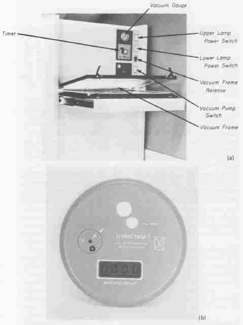
FIG. 10 Exposing photo-resist film: (a) exposure unit for double-sided
pc boards; (b) radiometer.
Proper exposure time for a particular resist and exposure unit must be determined empirically. For any exposure unit using a Stouffer 21-step expo sure chart, the procedure for this determination is detailed in Appendix XI. With the correct exposure time specified for the Laminar AX resist film, a radiometer, shown in FIG. 10b, is used to measure the UV light energy that strikes the film during exposure. The Dynachem Model 500 UV Integrating Radiometer shown measures the light energy in units of milli-joules per square centimeter. The direct liquid crystal digital readout allows for accurate and rapid monitoring.
The Dynachem radiometer is approximately 5 inches in diameter and only inch in thickness. This geometry permits its use in any area of the exposure frame, even in a vacuum frame. The procedure for using the radiometer to test the upper lamp of an exposure unit is as follows:
Step 1. The film manufacturer’s recommended exposure time is set with the Stouffer chart positioned under a clear area of the phototool. For a silver film phototool and Laminar AX resist, this exposure time is about 30 seconds under a 400-watt mercury vapor lamp.
Step 2. The radiometer is placed face up in the vacuum frame and the ON/RESET button is pressed. This will result in the display to show four zeros.
Step 3. The sensor area of the radiometer (a 1-inch-diameter white circle) is covered with a clear portion of the phototool.
Step 4. The vacuum frame is closed and the exposure unit energized for the time obtained in Step 1.
Step 5. At the completion of the exposure cycle, the radiometer display will read the standard exposure in milli-joules per square centimeter. For the Laminar AX film, this reading should be 55 mJ/cm^2 for the exposure time determined by the use of the Stouffer chart.
Step 6. The procedure is repeated to test the lower lamp of the exposure unit. The radiometer is positioned face down on top of a clear area of a phototool placed on the bottom glass surface of the vacuum frame.
The radiometer will automatically turn off in about 45 seconds if not exposed to UV light. The Dynachem unit is battery-operated and is equipped with a charger. It is rated for 8 hours of continuous use per full charge.
The radiometer is an essential tool for obtaining optimum imaging. It accurately monitors correct exposure time by indicating problems resulting from a decrease in UV energy caused by lamp output, voltage drop, dirty reflectors, or changes in the clear areas of the phototool. An undetected decrease in UV energy can result in imaged boards having resist patterns that will not with stand the plating and etching processes.
After the laminated pc board has normalized to room temperature, the circuit-side diazo phototool is aligned over the board using the underlying holes for registration. Two pieces of double-sided tape are placed on the phototool in the thief area (where they will not show) to contact the pc board. When this is completed, the board is turned over and the component-side phototool is registered and taped into position. The setup for exposure is shown in FIG. 11a. The phototools and pc board are placed onto the glass portion of the vacuum frame ( FIG. 11b). Notice the small wire lying in the vacuum frame. One end of the wire is positioned across one corner (thief area) of the board and the other end is placed into the vacuum port. This ensures rapid air removal from the frame so that the total surface areas of all elements will be pressed tightly together. For exposure, the plastic cover is lowered and locked into place over the setup. Engaging the vacuum pump will create a vacuum between the glass and the plastic sections of the frame forcing both the top and bottom positives into immediate contact with the polyester cover sheets of the dry film. A good seal is indicated by a reading of 25 psi for the unit illustrated in FIG. 10a. A good seal having been achieved, the frame is pushed into the exposure unit between the upper and lower lamps and exposed for the preset interval on the timer control. For the exposure unit shown, an exposure time of approximately 30 seconds, as determined with the step table, results in correct exposure for Laminar AX photo-resist to obtain a resist image that will withstand the subsequent plating processes.
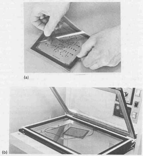
FIG. 11 Preparation for dry-film exposure: (a) alignment of photo-
tool with laminated board; (b) proper position of phototool on vacuum
frame.
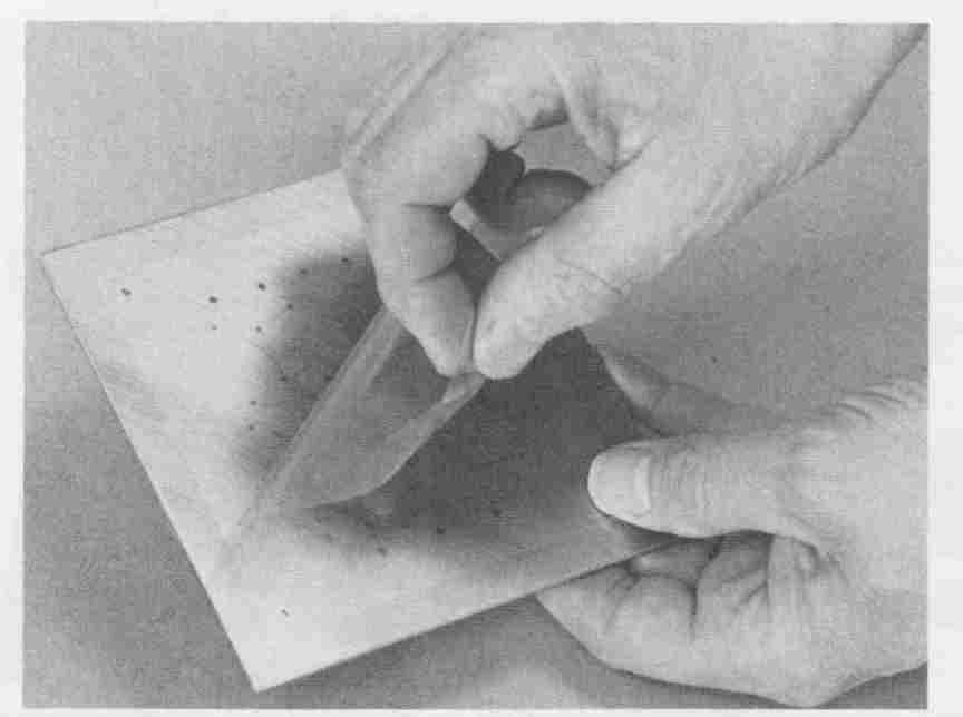
FIG. 12 Removal of protective polyester cover sheet after exposure.
As with any negative-acting resist, exposure of the film to ultraviolet light causes the following to occur. All those areas of the resist protected from the light (those areas appearing as amber conductor patterns on the diazo positive) will remain unchanged chemically and will be completely removed in the developing phase. Those areas that are exposed to the light (all transparent areas) are polymerized and will not be removed in the developing phase.
After the film is properly exposed, the vacuum frame will be automatically ejected from the unit. The vacuum pump is then turned off and both the exposed pc board with the phototool are removed from the unit.
At this point, a faint image of the conductor pattern is discernible through the transparent gas seal on the resist. This is the result of a visible indicator dye that was added to the film by the manufacturer. Again, the exposed pc board needs to be allowed to normalize to room temperature for approximately 30 minutes. The protective gas seal should remain in place and undisturbed during the normalizing period.
One side of a correctly exposed double-sided pc board with its protective polyester cover sheet partially removed (after the 30-minute normalizing period) is shown in FIG. 12. This board is now ready for developing.
7. SPRAY DEVELOPING
Spray developing, similar to other photographic processes, should be done in a gold-lighted area to prevent ultraviolet light from destroying the imaged boards. Spray developing is accomplished by spraying, under high pressure, a mildly alkaline developer solution onto the exposed pc board for a specific length of time and at a specific temperature. This temperature should be within the range 80 to 90°F (27 to 32°C). Higher developing temperatures will de crease developing time, but it may degrade the quality of the resist pattern remaining on the pc board. Too low a temperature will increase the required developing time. The prototype spray developer shown in FIG. 13 will completely develop a pc board in approximately 45 seconds at a temperature of 85°F (29°C) with new developer solution. Development time is determined by the “freshness” of the developing solution and its temperature. Optimum developing can be determined visually—all of the resist that was not exposed to the ultraviolet light is completely removed, leaving clear copper. A properly developed pc board is shown in FIG. 14. In mass-production conditions, an additional 15 seconds is added to the developing time to compensate for the fact that the more boards that are developed, the more resist goes into the developing solution resulting in longer time.
A developer that can be used for Laminar AX resist is a 1.5% by weight solution of trisodium phosphate (TSP) and tap water. For this solution, 0.125 pound (57 grams) of TSP per gallon of water is required. This solution is cost- effective but results in a relatively slow developer. Improved developing efficiency can be achieved with Dynachem’s concentrated developer solutions for Laminar AX resist. These developers are under proprietary trade labels of Concentrate Developer KB-1A and KB-1B. An example of preparing developing solution will make use of the spray developer shown in FIG. 13. This developer has a sump capacity of 10 gallons minimum and 15 gallons maximum.
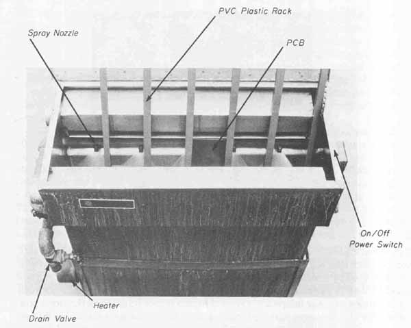
FIG. 13 Spray developing a pc board.
To prepare the developing solution, 12 gallons of cold tap water are placed into the developer sump. A measure of 1875 milliliters of Concentrate Developer KB-1A and 1875 milliliters of Concentrate Developer KB-1B are added to the water. To suppress the formation of excessive foam during the developing operation, the addition of Dynachem Antifoam No. 40 at the rate of one milliliter per gallon of developer will complete the solution. To the approximately 13 gallons of solution in the sump, 13 milliliters of Antifoam No. 40 is added. This solution will result in rapid and effective pc board developing. It should be mentioned at this point that with this developing solution, if developing time exceeds 1 minutes at a spray temperature of 85°F, this is an indication that the solution has been saturated with developed Laminar AX. It should be discarded and a fresh batch of developer prepared. In addition, the pH level of the solution should be monitored with a pH meter to avoid obtaining less durable resist images. The developer should be replaced when the pH level drops to a reading of 10.
In preparation for developing, the immersion heater temperature control is adjusted to 85°F and at least 1 hour should be allowed to pass for the solution to reach this operating temperature. After the solution has reached its operating temperature, the board to be developed, with both protective polyester cover sheets removed, is placed in a suitable rack and suspended into the spray. A slow up-and-down motion improves the uniformity of developing, as does rotating the entire rack 180° in the spray at least once for each batch of boards to be developed.
After developing, the board is immediately removed from the rack and given a rinse under a cold-water tap for at least 30 seconds on each side. Any developer solution remaining on the pc board after rinsing is neutralized with a 30-second dip in a diluted sulfuric acid solution. A 5% by volume solution is recommended. This solution is prepared by slowly adding 5 parts of CP sulfuric acid to 95 parts of tap water. After this neutralizing dip, the board is rinsed for 30 seconds and then allowed to air-dry.
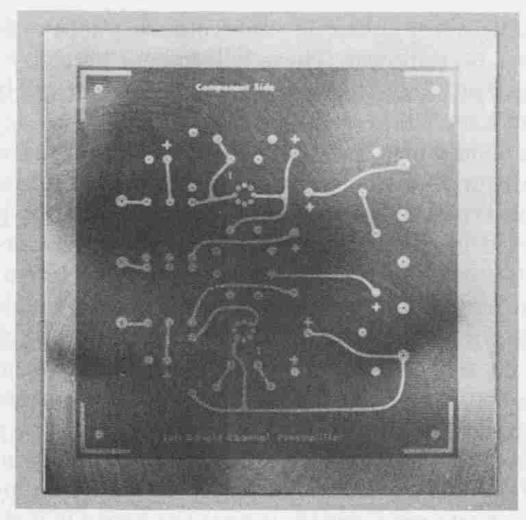
FIG. 14 A pc board after developing.
8. IMAGE TOUCH-UP
After the board has been properly developed and air dried, it is very critical that the images on both sides be carefully inspected for any defects. This inspection is best accomplished with the aid of a 5 x magnifier fitted with a 22- watt fluorescent lamp. The entire image and the surrounding film-resist areas should be examined. Any speck of undeveloped photo-resist in the pattern image should first be removed. These will appear as shiny and almost clear areas on the copper pattern. These particles can be removed by carefully scraping with the tip of a scalpel.
The boards should also be examined to observe if there are any voids or breaks in the surrounding film resist. If not corrected, these voids will leave unwanted copper exposed, which will result in conductor paths or terminal pads being shorted in the electroplating process. These areas are easily re paired with the use of a special fiber-tip ink-resist pen. Two types of dry-film touch-up pens are available. One is coded with a red top and is made to be used with photo-resist films that can be stripped in an alkaline solution. This is the type that would be used with the Laminar AX film. The other touch-up pen is coded with a blue top and is used with photo-resists that must be stripped with a solvent. It is important that the touch-up ink selected be removed with the same stripper used to remove the dry-film resist on which is it used. This will avoid additional processing steps. By simply filling in any breaks with the resist ink, possible shorts are avoided. Before the board is further processed, all touch-up ink must be allowed to completely dry.
After the board has been inspected and any necessary repairs performed, it is ready for the remaining phases of processing to complete its fabrication. These processes, discussed in Section 19, are pattern plating, solder plating, dry-film stripping, etching, and solder fusion followed by cutting the board to final size.
EXERCISES
A. Questions
1 What is the purpose of baking the mechanically cleaned copper panels at 150°F for 15 minutes prior to dry-film application?
2 List three precautions in the handling of dry film.
3 What are the three laminator settings and their values for thy-film laminating?
4 Explain the term heat fog and how it is avoided.
5 Explain the term gas seal.
6 Why does the manufacturer of dry film specify a 30-minute normalizing period after thy-film lamination?
7 Explain the procedure for determining proper exposure for dry-film resist using a Stouffer chart.
8 Calculate the required amount of trisodium phosphate to make a 20-gallon developing bath for Laminar AX film.
9 How much Antifoam 40 should be added to a 20-gallon developing bath?
10 What is the purpose of the neutralizing bath after boards have been developed and what is its makeup?
11 After the pc board has been exposed through the diazo phototool, from which areas is the resist removed by the developing process?
12 What is the approximate vacuum gauge reading that will result in a good seal in the exposure unit?
13 In how much time can a pc board be developed in a spray developer having a developer solution temperature of 85°F?
B. True or False
Select T if the statement is true, or F if any part of the statement is false.
1 The copper surfaces of pc boards are chemically cleaned in a 20% by volume solution of sulfuric acid and water for about 2 minutes. T F
2 When mixing acid solutions, the water is slowly added to the acid. T F
3 Prior to dry-film laminating, the cleaned pc boards are baked for approximately 15 minutes at 150°F. T F
4 The laminating feed rate is approximately 15 linear feet per minute. T F
5 Heat fog is caused by leaving the pc boards in the oven for too long. T F
6 Immediately after a pc board is laminated, the polyester cover sheets are removed and the board is allowed to normalize for approximately 30 minutes. T F
7 Developing solution for Laminar AX should be used at a temperature of approximately 85°F and replaced when the pH level drops to 10. T F
C. Multiple Choice
Circle the Correct answer for each statement.
1 To prepare a 10% solution of sulfuric acid, one part of acid is slowly added to (9, 10) parts of cold water.
2 Chemical cleaning of a pc board requires (alkaline, acid) followed by a mechanical scrubbing.
3 The recommended laminating temperature of dry-film photo-resist is (235°F, 361°F).
4 After the photo-resist laminating process is completed, a normalizing time of (30 minutes, 30 seconds) is required prior to further pc board processing.
5 The developing solution for Laminar AX requires (sulfuric acid trisodium phosphate).
6 The development of Laminar AX is accomplished by (spraying, dipping) with a solution temperature of (60°F, 85°F).
D. Matching Columns
Match each item in column A to the must appropriate item in column B.
COLUMN A | COLUMN B
1. Diazo 2. Dry-film photo-resist 3. Trisodium phosphate 4. Stouffer chart 5. Antifoam No. 40 6. Normalizing time |
a. 21-step exposure table b. Developing process c. Phototool d. TSP e. 30 minutes f. Polyester cover sheet |