AMAZON multi-meters discounts AMAZON oscilloscope discounts
5. WRENCHES
Wrenches are necessary for larger nuts found on some potentiometers and switches when a suitable nutdriver is not available or when accessibility does not permit its use. The most common types of wrenches used in electronic assembly are the box, open-end, and adjustable wrenches shown in FIG. 13.
The box wrench, similar to a nutdriver, requires complete access over the nut since it encircles and grips the nut at its points. This wrench is a 12-point drive as opposed to the 6 points of a nutdriver. If used to secure a hexagonal nut, all 6 of the points will be contacted, virtually eliminating the possibility of shearing or rounding the points. The box wrench is preferable over other types of wrenches because it is much less likely to gouge the work surface. The box wrench should fit snugly onto the nut. All sizes listed for the nutdriver are also available for the box wrench, in addition to larger sizes that are not normally required in electronic assembly. Lengths of 4 to 6 inches are suitable for most assembly applications. The proper use of a box wrench used to secure a potentiometer to the front panel of the amplifier is shown in FIG. 14. Masking tape may be applied to the panel where the edge of the wrench would contact the work surface around the nut to eliminate the possibility of damaging the finish.
Open-end wrenches are primarily intended for use with square nuts. The proper-size wrench can be determined when the entire length of the inside faces of the jaws fit snugly against any two opposite flats of the nut. This ensures maximum surface contact and minimizes slippage and rounding of the nut. The jaws of this wrench are generally angled at 15 degrees to the handle center line. This design makes it possible to work in confined areas where the nut can only be turned partially. Open-end wrenches for electronic assembly are available in a complete range of sizes from to 1 inch and between 3 to 10 inches long. Although available in sizes much larger than 1 inch, these are seldom required in electronic applications.
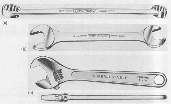
--- FIG.—13 Wrenches. (a) Box; (b) open-end; (c) adjustable.
Both the box and open-end wrenches require a complete set to accommodate all possible nut sizes that may be encountered in assembly. The adjustable wrench eliminates the need for complete sets since the distance between jaws can be changed to any size within its capacity. It does not, however, provide as secure a grip as either the box or open-end wrench. The adjustable wrench is similar to the open-end wrench with the 15-degree angle except that only one jaw is stationary. The second jaw can be moved by means of a thumb-operated adjusting screw located within the head of the wrench. To adjust the wrench for proper fit, the jaw is first opened sufficiently to allow both jaws to easily slip over opposite flats on the nut. The movable jaw is then closed until both jaws are gripping firmly against the flats. It is important that when positioned, the pulling force should be applied to the stationary jaw. If excessive force is applied to the movable jaw, the adjusting screw may be damaged or the wrench could slip, damaging the work surface or surrounding parts.
6. POP RIVETS
An alternative method of securing sheet metal or hardware by means other than machine screws and nuts or sheet metal screws is with the use of pop rivets. Pop riveting is rapid, requires little skill, and free access to only one side of the work is necessary. The only tool used for this process is a hand-type riveting gun.
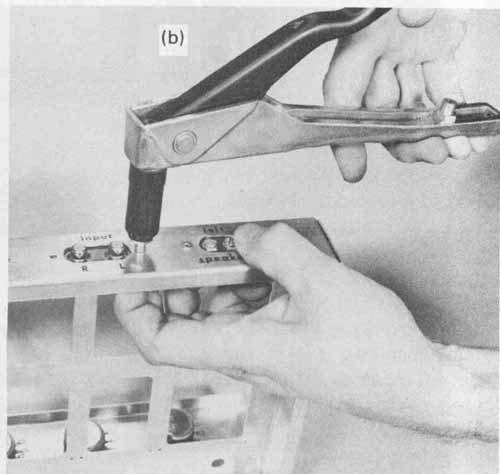
A typical pop rivet, shown in FIG. 15a, consists of a truss style head sealing plane, hollow shaft, stem, and button head. The stem is tapered near the button head. When a tensile force is applied to the stem, the button head is drawn up into the hollow shaft. This action flares the end of the rivet against the metal, thus providing a positive fastening of the metal parts. When a pulling force of from 500 to 700 pounds is reached, the stem will break at the tapered section. The sheet metal or hardware to be fastened must be provided with clearance holes to accept the shaft of the rivet. A clearance of 3 to 5 thousandths of an inch is sufficient. The shaft is then pressed through the holes with the sealing plane flush against the metal surface. The pulling force is applied to the stem through the locking action of the pop rivet gun nose piece (stem collet). The nose piece is placed over the stem and pressed flush against the head of the rivet (Fig 23.15b). As the operating lever of the gun is squeezed, the stem of the rivet is gripped, drawing the button head upward into the hollow shaft. Continued squeezing of the operating lever will create the desired flaring action. The stem is broken when sufficient pulling force is reached. The operating lever may have to be actuated more than once to complete this operation. When the lever is again released, the broken stem drops out c the nose piece. An installed pop rivet is shown in FIG. 1 5c.
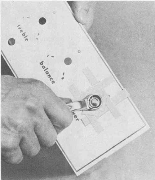
--- FIG.—14 Box wrench used in assembly.
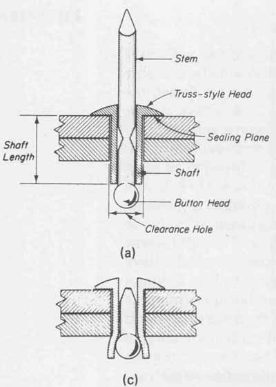
--- FIG.—15 Pop rivet and its assembly: (a) pop rivet assembly and nomenclature;
(b) pop rivet gun positioned against rivet head; (c) installed pop rivet.
Rivets are a permanent type of fastener intended for i if components, sheet metal, or hardware are not to be removed once fastened. This fact must be considered when using rivets since they are difficult and time consuming to remove. If it is necessary to remove a rivet, drilling through the rivet center with a drill bit size which is at least equal to the clearance hole is required.
Pop rivets of the style described are available in steel or aluminum with shaft diameters of , , and inch and shaft lengths of to inch. The clearance hole drill numbers for these three diameters are Nos. 30, 20, and 11, respectively. The stems of the three available shaft diameters require their own nose piece on the pop rivet gun. These nose pieces thread into the gun assembly and are easily removed with an open-end wrench.
7. PLIERS FOR HARDWARE ASSEMBLY
The two types of pliers most commonly used in electronic assembly are the long nose and the gas pliers. These are shown in FIG. 16. Both styles consist of a pivot, jaws, and handles.
The long-nose pliers consist of a pair of long, narrow tapered jaws. These jaws are smooth or may have serrations near the tips for improved gripping. These pliers are designed to aid in assembly for holding or positioning small parts in tight spaces where finger accessibility is limited. They are not intended to withstand severe gripping or twisting forces and should not be used for tightening machine nuts. Misusing the tool in this way could cause the jaws to spring out of alignment, rendering the pliers useless. Long-nose pliers holding a machine nut for assembly are shown in FIG. 16a.
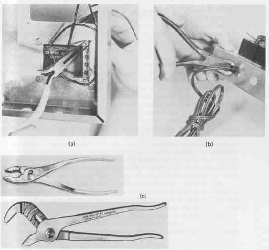
--- FIG.—16 Pliers for hardware assembly: (a) long-nose pliers aid in
assembling small parts; (b) gas pliers used to install power cord strain
relief; (c) slip- and rib-joint pliers. Courtesy of Utica Tool Company,
Inc.
Gas pliers have a much more rugged design than long-nose pliers and have coarse serrations over the complete inside surface of each jaw. These pliers are used primarily for holding round stock, such as inserting a power cord strain relief bushing, as shown in FIG. 16b. Excess gripping force on soft material should be avoided because the serrated jaws will mar the surface. For this reason, gas pliers should be used with extreme care. A minimum of two layers of masking tape wrapped around the stock will help prevent the jaws from mar ring.
Although many other styles of pliers are available, such as the slip-joint and rib-joint types, shown in FIG. 16c, they are designed for holding heavy stock in which marring of the surface is not a factor. They should not be used in place of any of the drivers, wrenches, or pliers discussed in this section. Special pliers for cutting wire will be considered in Section 24.
8. TAPS AND DIES
Taps and dies are thread-cutting tools constructed of hardened steel. The tap is used to cut internal threads into predrilled holes for accepting screw threads. The die will cut external threads on rod stock for assembling nuts. Normally, the thickness of the metal used to form chassis is too thin to allow an adequate number of threads to be tapped. For screws to be mechanically secure, a metal thickness that will allow a minimum of three full threads to be cut is required. For this reason, components and hardware mounted to chassis use either ma chine screws and nuts, sheet metal screws, or rivets. In applications in which one of these three methods is not desirable, special fastening techniques, discussed in Sec. 9, can be employed. However, the use of taps and dies is some times the only practical alternative to make an effective and neat fastening.
A tap with its nomenclature is shown is FIG. 17a. Taps are available in common machine screw sizes and are designated identically. For example, a hole formed for a 4-40 machine screw is cut with a 4-40 tap. Three basic hand taps are shown in FIG. 17b, the (1) taper tap, (2) plug tap, and (3) bottoming tap. The distinction in each style is in the amount of chamfered taper at the front end of the threaded section. As can be seen in FIG. 17b, taper taps have the most prominent taper and are preferable for starting threads. For this reason, they are sometimes referred to as starter taps. The taper tap is used for threading through holes (passing completely through the work). For blind holes (terminating at some depth within the work) tapping involves a sequence of operations. The thread is first started with a taper tap. Owing to its chamfered taper, the last several threads toward the bottom of the hole cannot be cut. For this reason, the plug tap is used next to cut all but the last few threads. To thread a blind hole completely to the bottom, a bottoming tap is finally used to form the remaining threads.
The design of a tap is similar to that of a drill bit. It is fluted to allow entry of lubricants as well as to provide space for chips to accumulate while thread cutting. The number of flutes will vary depending on the size of the tap, with the smaller taps having three flutes and the larger ones having four.
Hand tapping is accomplished with a tap secured in a chuck handle T style tap wrench. This is shown in FIG. 18. This wrench grips the tap in the i nf it. chuck, which is rotated to secure the tap in place.
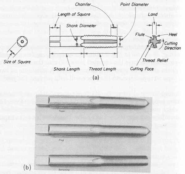
--- FIG.—17 Tap nomenclature and styles: (a) machine screw tap nomenclature;
(b) tap styles.
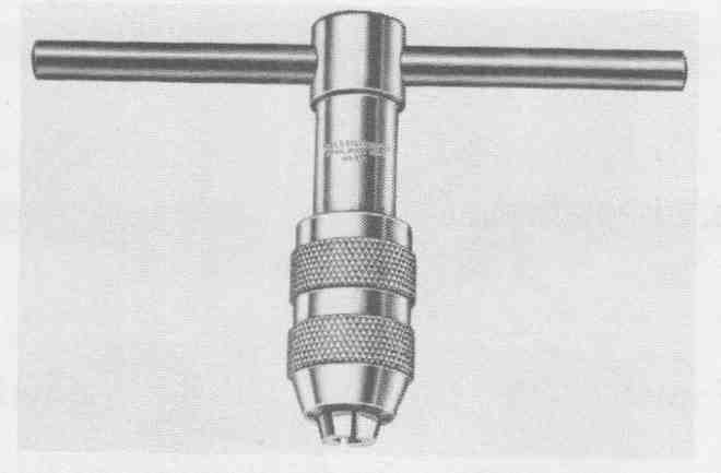
--- FIG.—18 Chuck handle T-style tap. Courtesy of the L.S. Starrett
Company, Athol, Mass.
The tapping operation begins by drilling a hole whose diameter is equal to the minimum diameter of the required screw (dimension T in FIG. 1 d). The correct tap drill sizes for most common screws are given in Appendix IX for various metals. When the correct-size tap hole has been formed and the taper tap is secured into a tap wrench, a lubricant is applied directly to the tap. The tapered end of the tap is positioned into the hole perpendicular to the work surface. When a great deal of tapping is to be done, small hardened steel blocks (tapping blocks) with predrilled clearance holes for various tap sizes are extremely useful. With the tap positioned in the tapping block, proper tool alignment will be achieved when the block is in contact with the work surface and their holes are aligned. With the tap positioned, it is gently rotated clockwise (for right-handed threads) with a uniform downward pressure. After the first half-turn, the tap is rotated in the reverse direction for at least one-quarter turn. The purpose of this technique is to break the chips generated and to clean them into the flutes, where they fall toward the bottom of the hole. This procedure is continued throughout the tapping process. After the first two or three full turns, downward pressure on the tap is no longer required since it reaches a point where it threads its own way into the work. When working with hardened materials, considerable resistance to the tap may be encountered. If an unusually high spring effect is felt at the handle of the tap wrench, this is an indication that the tap is jammed in the work. The tap is extremely brittle and is easily broken. When this excessive resistance to thread cutting is encountered, the cutting rotation must immediately be reversed to break the bound chips and additional lubricant added to the cutting area by way of the flutes. For through holes, a fine wire may be passed through each flute to help dislodge the broken chips. This is not recommended for blind holes since the chips may be compressed, causing the tap to jam in either direction. When working on blind holes, the tap must be removed periodically so that the chips may be shaken or blown out. It may be that forward rotation may be limited to something less than one-half turn with a necessary reverse turn of one-half to three-quarters. Each technician must develop his or her own procedures based on personal experience. It must be emphasized that a broken tap is virtually impossible to remove without damaging the work surface. When working with a specific metal for the first time, it is advisable to experiment on a piece of similar scrap stock to gain experience in the necessary sequence of forward and reverse rotation.
The purpose of the lubricants introduced through the flutes is to reduce friction between the tap and the work and to prolong tool life. For this reason, lubricants should be used freely. A table of cutting lubricants for several common materials is given in Table 6.1.
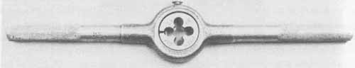
--- FIG.—19 Die stock with die inserted.
Although dies are available in several styles, the split die is the most commonly used and will be discussed exclusively (see FIG. 19). The center of the die has cutting threads that are interrupted by holes along the perimeter of the threads, giving the appearance of a clover. The purpose of these holes is for chip relief. On one side of the die, the threads are chamfered outward and away from its center line to facilitate alignment with the work. An adjustment screw is located in the perimeter of the die to obtain the desired fit. This is a trial-and- error process. If too much stock is cut where a tight fit is desired, the threaded portion is cut off and the adjusting screw tightened. On the other hand, if not enough stock is cut to provide a loose fit, the adjusting screw is loosened and the die is run over the first set of threads to cut them deeper.
The die is used in conjunction with a handle termed a die stock. Both die and die stock are shown in FIG. 19. The die is positioned with its un chamfered thread closest to the inside shoulder of the die stock and held firmly in place with a set screw that aligns with a recess provided along the outer edge of the die. With the die secured in the die stock, the work is held in a vise or other suitable clamp. The chamfered threads of the die are properly aligned when the handles of the die stock are perpendicular to the work. Similar to the tap, the die is rotated first with a forward one-half turn followed by a reverse one-quarter turn to clear chips. Lubricants recommended for tapping are also used for dies.
Dies, as well as taps, are designated in sizes identical to those of machine screws. An 8-32 die will cut 32 threads per inch on stock whose diameter before threading is 0.164 inch.
Forming threads by hand is one of the most difficult machining operations because of chip removal and tool alignment. The important factors to consider for obtaining the desired threads are (1) proper size of predrilled hole or diameter of stock, (2) correct size and type of tap or die, (3) recommended lubricant, and (4) proper alignment between the tool and the work.
9. SPECIAL FASTENERS AND HARDWARE
There arise many instances in which the conventional fastening methods do not completely satisfy the assembly requirements because of many reasons, such as accessibility, orientation, frequent removal, and location. Many special fasteners and hardware that find wide application in electronic assembly are commercially available. Some of the more common of these will be discussed here.
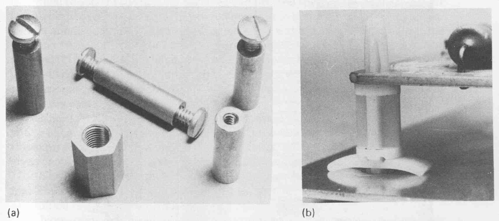
An alternative method of fastening components to sheet metal or securing chassis elements is with the self-clinching nut, shown in FIG. 20a. This type of nut provides a means of securing to sheet metal with a machine screw thread and is capable of being used with metal stock as thin as 0.03 2 inch. Self clinching nuts are available in steel, stainless steel, and an alloy of aluminum and Monel. The knurled clinching ring grips the sheet metal, causing it to be pressed around the tapered base forming a permanent bond as the nut is forced into the metal. These nuts are available in thread sizes from 2-56 to -20.
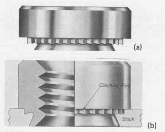
--- FIG.—20 Self-clinching nut; (a) raised self-clinching nut style;
(b) installed self-clinching nut. Courtesy of Penn Engineering and Manufacturing
Corp.
To attach the self-clinching nuts into the sheet metal, a hole from 0.166 inch for the 2-56 nut to 0.656 inch for the -2O size is required. The tolerance for this hole must be within + 0.003 inch to — 0.000 inch for maximum gripping of the clinching ring and tapered base into the sheet metal. The base of the nut is inserted into the hole with the clinching ring against the work surface. The nut is then pressed into the metal with a hydraulic press. The installed self-clinching nut, shown in FIG. 20b, is a raised design. Flush-mounted, threaded stud, and solder terminal designs are also available.
The layout design may specify a single wire or cable to pass through a hole formed in the metal chassis element. For this requirement, a grommet should be used to prevent damage to the wire installation. A grommet is a rubber insulator that “cups” around the hole in the chassis and prevents wires from rubbing against the metal edges. A grommet being inserted into the amplifier’s main chassis element is shown in FIG. 21a. An access hole must be provided in the chassis that is equal to dimension A in FIG. 21b. Some common size soft-rubber grommets together with the necessary size of access hole for each are listed in TABLE 4. Although dimension A is the grommet size designation, the selection of the proper-size grommet depends on the minimum required size of dimension B.
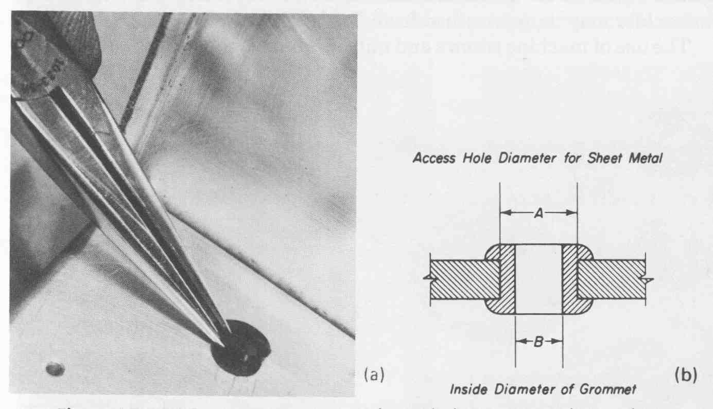
--- FIG.—21 Grommets are inserted into holes to cover sharp edges: (a)
grommet installation technique; (b) important dimensions for grommet
installation.
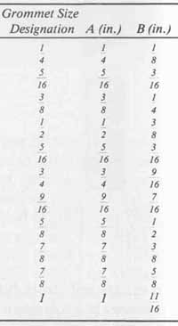
--- TABLE 4 Rubber Grommet Dimensions
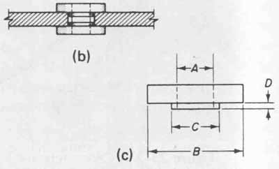
--- FIG.—22 Fiber shoulder washers: (a) common shoulder washers; (b)
recommended method of assembly; (c) important shoulder washer dimensions
for installation.
If the packaging design requires that a machine screw or other metal stud be insulated from the chassis, fiber shoulder washers, such as those shown in FIG. 22a may be used. Two washers are necessary, as shown in FIG. 22b, to ensure complete electrical insulation of the stud from the surrounding metal edges of the access hole. The major diameter of the stud used determines the size of dimension A in FIG. 22c, whereas dimension B is the outside of the washer. Dimension C is the outside diameter of the shoulder for which the access hole in the metal must be formed, and dimension D corresponds to the shoulder height. If the height of the shoulder is more than one-half the thickness of the metal, a flat fiber washer may be necessary in place of a second shoulder washer to ensure flush mounting and total insulation. The appropriate size shoulder may be determined from TABLE 5.
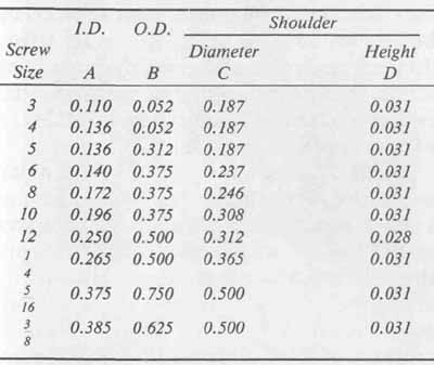
--- TABLE 5 Fiber Shoulder Washer Dimensions
The use of machine screws and nuts, as used to mount the seven pc boards in the amplifier shown in FIG. 25, is one acceptable mounting arrangement. However, large areas of metal must be removed from the chassis. The sheet metal work could be reduced by the use of standoffs and circuit board supports, which often find application in prototype as well as production assemblies. This hardware is shown in FIG. 23. Straight standoffs are made of plastic for applications requiring electrical insulation and are available in lengths from to several inches. Standoffs, shown in FIG. 23a, are threaded at both ends for mounting and will accept a screw size range of No. 4 to No. 10. Hinged stand offs are available in cadmium-plated brass. Both ends of this style standoff are threaded for mounting to accept screw sizes from 4-40 to 8-3 2.
By drilling holes into the four corners of the pc board, straight standoffs may be used between the board and chassis to support the board away from the chassis surface. The length of standoff is determined by the tallest projection or component extending from the side of the pc board that faces the chassis. A minimum of inch must be added to this dimension to ensure adequate clearance.
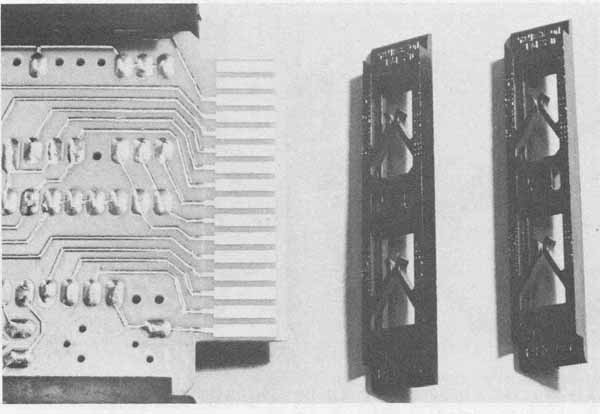
--- FIG.—23 Hardware for mounting printed circuit boards: (a) threaded
standoffs; (b) nylon printed circuit board support.
The hinged standoff is generally selected to make circuit testing or servicing easier. Two corners of the pc board are fastened to hinged standoffs and the two opposite corners are secured to standard standoffs. The height of the hard ware must be selected to allow the board to rest parallel with the chassis surface with sufficient clearance. For servicing, the two screws at the corners of the board secured to the standard standoffs are unfastened. The board can then be lifted upward to an angle of 90 degrees by the pivoting action of the hinged standoffs, thereby exposing wiring and components for testing and repair. This method of mounting not only provides easy access for repair, but also can re duce the overall package size.
Circuit board supports, shown in FIG. 23b, are available in nylon and other plastic materials. They consist of two snap-lock arrangements, one at each end of the support. For mounting, one end of the support snaps securely into a 0.187-inch-diameter hole drilled into the chassis. These supports provide another convenient method of mounting pc boards to chassis. The board is se cured to the upper end of the support by a spring-type locking action. Support heights range from to inch. Circuit board supports can be mounted on all four corners of small boards. More may be used on larger boards for greater support. They have the advantage of allowing boards to be removed and quickly replaced and eliminate the need for removing large areas of metal from the chassis. These circuit board supports can be used in conjunction with connectors mounted for electrical interconnections between the board and chassis, which adds to the versatility of this method of mounting.
Printed circuit board guides, shown in FIG. 24, are grooved runners made of plastic and designed for use with edge connectors. These guides ensure alignment between the edge of a pc board and a connector and also provide additional support for the board. Generally fastened to the chassis with machine screws and nuts, pc board guides are also available with an adhesive backing for rapid attachment. The grooves in these guides are designed to accept all standard board thicknesses.
The final method of fastening to be considered is the use of adhesives, particularly epoxy resins. High-strength adhesives find wide application in electronic packaging since they provide a number of advantages over other methods of bonding. Some of these advantages are elimination of machine operations, provision of electrical insulation and low thermal resistance between parts joined, and uniform stress distribution over the entire bonded area. Al though the use of adhesives requires thorough preliminary cleaning of parts and often heat and pressure during the curing period, the advantages of this method of bonding far outweigh the time necessary for its proper use.
--- FIG.—24 Printed circuit grooved guides.
Epoxy resins must generally be mixed with a catalyst (hardener) prior to use. The parts are measured by volume or weight. Manufacturers’ mixing instructions must be consulted for the correct amounts for a specific epoxy since there is a wide variation among the many different adhesive types. The working time (time between mixing and initial hardening) must also be predetermined for the specific epoxy to avoid mixing more than can be used during the prescribed time.
For proper bonding, the surfaces must be thoroughly cleaned. Fine emery cloth to remove oxides may be used followed by degreasing with a solvent such as toluene or trichlorethylene. After the epoxy is properly mixed, a thin coating is applied to each of the mating surfaces and pressed together to squeeze out air bubbles and excess adhesive. Improved bonding to aluminum results if the surface is anodized prior to bonding. Depending on the epoxy used, curing time will vary from 5 minutes to 24 hours at room temperature. These periods can be reduced if the bonded surfaces are baked in an oven but care must be exercised not to exceed the temperature range of the epoxy. In addition, baking is not recommended when bonding devices to heat sinks because of the possibility of damaging components.
Epoxy is used for bonding when the stresses encountered will be only tensile or shear. Since the shelf life of many adhesives is often less than one year, the expiration date must not be exceeded for sound bonds. In addition, adhesives should be stored in a cool area to ensure longest possible shelf life.
The hardware and pc boards of the amplifier have been assembled using materials and techniques discussed in this section. The amplifier completely assembled is shown in FIG.
Now that assembly is completed, wiring of the boards and chassis mounted hardware are necessary to complete the amplifier. In the next section we consider wire and wiring assembly techniques.
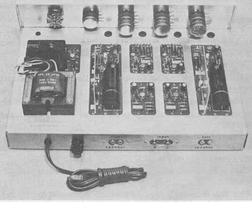
--- FIG.—25 Completed mechanical assembly of all amplifier parts to
chassis and front panel elements.
EXERCISES
A. Questions
1 List the four major factors in electronic packaging which are required for quality workmanship.
2 List the eight features that distinguish machine screws.
3 What is the advantage of the use of Phillips head screws over slotted head screws?
4 Define the term fit as it pertains to machine screws.
5 What is the major difference between thread-forming and thread-cutting screws?
6 For fastening two pieces of 18-gauge aluminum with a No. 6 sheet metal screw, determine the required clearance hole size and tap hole size. Refer to Appendix VI and FIG. 7.
7 What is one disadvantage of using pop rivets rather than screws and nuts?
8 What hole diameter is required to install a grommet having an inside diameter of inch? Refer to FIG. 21b and TABLE 4.
8. True or False
Circle T if the statement is true, or F if any part of the statement is false.
1 Flat head machine screws are recommended for use on thin sheet metal. T F
2 The Allen drive configuration has a more positive tool positioning and gripping action than the Phillips head. T F
3 The UNC system has fewer threads per inch than the UNF system. T F
4 For most electronic assembly applications, the Class 3 machine threads are standard. T F
5 The tooth-type lock washer should not be reused when removed. T F
6 Split lock washers are more effective than any other type of lock washer. T F
7 Self-tapping screws are intended to be used for sheet metal fastening applications. T F
8 Pop rivets are used where a permanent type of fastener is required. T F
9 The diameter of a hole for the installation of a grommet is the same dimension as the grommet size designation. T F
10 Hinged standoffs are used to improve access to wiring and components. T F
C. Multiple Choice
Circle the correct answer for each statement.
1 Some common machine screw head styles are binder, round, and (oval, slotted).
2 For equivalent screw sizes, (UNC, UNF) screws have more threads per inch.
3 Machine screws with a (Class 1, Class 2, Class 3) screw thread are considered as having a snug fit.
4 Pop rivets are a (temporary, permanent) type of fastener.
5 Internal threads are cut into metal stock with the use of a (tap, die).
6 Shoulder washers are usually made from (meta4 fiber) in order to provide electrical (isolation, conduction).
D. Matching Columns
Match each item in column A to the most appropriate item in column B.
COLUMN A | COLUMN B
1. Class 2 2. Hexagonal drive 3. Shoulder washer 4. Lock 5. UNF 6. Split-joint 7. Grommet 8. T-handle |
a. Wire protector b. Washer c. Tap wrench d. Fine thread e. Allen f. Insulation g. Free fit h. Pliers |
E. Problems
1 Design and fabricate a steel tapping block having approximate dimensions of inch by 2 inches by inch. Referring to Appendix VI, determine the clearance hole sizes for gauge numbers 4, 6, 8, and 10 machine screws. Drill four evenly spaced holes to the sizes found in the table. Label the holes for the corresponding gauge. Break all sharp edges with the appropriate file and give all surfaces a light coat of oil to prevent rusting.
2 Using an appropriate epoxy, bond the two halves of an ink eraser to an aluminum handle such as that shown in FIG. The handle is fabricated from 16-gauge aluminum having blank dimensions of inch by 10 inches and bent around a 5/8-inch-diameter dowel.
3 Select an appropriate epoxy and seal the four corners of the soldering iron tip cleaning sponge tray constructed in Problem 15.1.
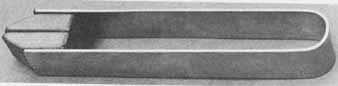
----FIG.—26
4 Design and construct a test jig stand for mounting printed circuit device test jigs designed and completed in Problems 11.2, 13,2, 14.2, and 15.2. Break all sharp edges with the appropriate files. Identify each test jig position on the stand with appropriate dry transfer letters, and numbers.
5 Mount the lamp (L1), on-off switch (S8), and battery clip for the seven- fixed-interval UJT timer printed circuit designed and fabricated in Problems 11.3, 13.4, 14.3, and 15.3 onto the chassis fabricated in Problem 8.5. The pc board may be mounted onto the chassis with standoffs or by flush mounting using the appropriate size mounting hole. Consideration must be given to providing access to the pc board-mounted time interval switch. Wiring among chassis-mounted components and hardware and the pc board is done in Problem 24.5.
6 The meter for the tachometer printed circuit designed and fabricated in Problems 11.5, 13.3, 13.6, 14.5, and 15.5 may be mounted onto a panel of the same design as that shown in Fig. 5.15. The pc board is to be mounted with proper length spacers and mounting screws to the rear of the meter, which in turn is secured to the panel. Wiring for the installation of the tachometer is done in Problem 24.6.