AMAZON multi-meters discounts AMAZON oscilloscope discounts
LEARNING OBJECTIVES:
Upon studying this section on hook-up wire and interconnection techniques, the student should be able to:
1. Know the composition, configurations, and size designations of common hook-up wire.
2. Calculate the resistance of a given length of wire.
3. Measure the diameter of wire.
4. Be familiar with the various types of wire insulation material and their characteristics.
5. Select the proper type of wire insulation for a specific application.
6. Know the common types of special wire configurations and their applications.
7. Be familiar with the wire color-coding system.
8. Use mechanical strippers to remove wire insulation.
9. Prepare wire for soldering.
10. Form proper wire connections on a variety of terminals.
11. Use crimp-type terminals.
12. Use manually operated wire-wrapping and de-wrapping tools.
13. Understand the use of semiautomatic and fully automatic wire-wrapping machines.
14. Use proper bussing techniques on wire-wrapped terminals.
0. INTRODUCTION
One of the least emphasized and perhaps the most important aspect of packaging is the selection of the most suitable hook-up wire for a specific assembly. From the standpoint of reliability, this selection must be based on such factors as conductor material and plating, conductor size, type of insulation, flexibility, environmental factors, and current and voltage limits, as well as cost. This section provides guidelines to aid in evaluating and selecting wire. Coupled with the problem of selecting are the methods for interfacing interconnections. Since there are a variety of standard interconnections (in addition to many special types), this section also includes pertinent information for evaluating the suitability of various connection methods.
Specific information also is provided here on common conductor materials and platings and American Wire Gauge (AWG) classifications of size, along with a comparison of solid wire with various types of stranded wire. Typical types of insulation are examined with respect to their application, including color-coding methods. Additional information is provided on current, voltage and mechanical and environmental criteria to allow for a total understanding of wire selection from the many types commercially available. Special wire types also are discussed.
Methods of interconnections are introduced, and the tools used for wire preparation and mechanical assembly are described, such as strippers, diagonal cutters, and others. Wrap-around and feed-through connections as they apply to swaged solder-type terminals, eyelet-type terminals, and solder lugs are discussed and expanded to include special hardware connections, such as solder pots, plugs, and jacks. Finally, solderless wiring techniques, such as solderless or crimp-type connectors and wire-wrap connections are set forth.
1. CONDUCTOR MATERIALS AND WIRE CONFIGURATIONS
Most of the wire used for electronic interconnections is fabricated from annealed (softened) copper. Copper used for this purpose is termed Electrolytic Tough Pitch (E.T.P.). Although other materials, such as aluminum, steel, and silver, are employed in wire construction, they are not common to electronics fabrication. Alloys of copper have been developed, however, which display superior characteristics when compared to pure copper. Although pure copper possesses excellent electrical conductivity characteristics as well as being malleable and ductile, it has the pronounced disadvantage of being highly susceptible to fractures under vibration and flexing conditions. Modern high- temperature annealing techniques, however, have made it possible to develop high-strength alloys with improved fatigue life. Some of these common high- strength alloys are cadmium-copper, chromium-copper, and cadmium- chromium-copper. One disadvantage in using these alloyed wires is that they are available only with coatings of silver or nickel, which are both expensive and difficult to solder. Tin-coated high-strength alloys are, unfortunately, not readily available.
Copper wire is usually coated, because pure copper oxidizes quickly when exposed to the atmosphere. Tin is the most common coating, although silver and nickel coatings are used in special applications. Tin-coated wire, recommended for applications wherein environmental temperatures will not exceed 150°C (302°F), is the least expensive of the three coatings mentioned. In addition, tin coating improves solderability. Silver coating, recommended for use in temperatures ranging from approximately 150 to 200°C (302 to 3950 F) greatly improves solderability but tends to corrode at elevated temperatures. Silver is the most expensive coating of those mentioned. Nickel coating is capable of oxidation protection to temperatures of up to 300°C (575°F) but requires activated fluxes and high-temperature soldering techniques.
Tin-coated wire is by far the most commonly used in the electronics industry. Tin is applied to the bare wire by either dipping or electroplating. Dipping is the least expensive method and is used if uniform plating thickness is not critical. Electroplated tin should be specified if close tolerance automatic strip ping is to be employed, since uniform plating is achievable by this method.
Wire used in the electronics industry can be divided into two groups: solid and stranded. Generally, solid wire that is comparable to a specific size of stranded wire is less expensive to manufacture and subsequently less expensive to purchase. Solid wire, however, does not possess the flexibility characteristics or the fatigue life of stranded wire. Whereas solid wire tends to fracture even under mild flexing, stranded wire remains highly flexible. Because much of the electronic equipment produced today is exposed to some form of vibration under normal use or has wiring flexibility requirements during assembly, stranded wire is the type most often specified.
Solid wire finds extensive application in the fabrication of leads for small components, such as resistors, capacitors, and solid-state devices. Hook-up applications of solid wire are generally limited to conditions wherein flexibility is not a criterion or lead runs are to be short, rigid terminations such as the direct connection of two closely spaced swaged turret-type terminals on a pc board. Solid, uninsulated tinned copper wire used as a short jumper or as a common circuit point is termed bus wire.
When longer lengths of bus wire are needed, it is usually recommended that the wire be straightened prior to its use. The best way to straighten wire is to secure one end of it in a vise and the other end in the chuck of a hand drill (eggbeater). All that is usually required to straighten the wire is 8 to 10 complete turns of the drill in one direction followed by an equal number of turns in the opposite direction while applying continuous tension to the wire.
Stranded wire is classified as either bunch or concentric. Bunch-type stranded wire is constructed of several small-diameter solid wires “bunched” together without regard to symmetry. Although the cost of bunch wire is low and it is extremely flexible, it does not have a consistent diameter. Because of this disadvantage, it is not recommended, because modern insulation stripping tools may nick or break individual strands, which will weaken the wire as well as reduce current capacity.
Concentric-type stranded wire overcomes the disadvantages of bunch wire in that its consistent circular cross section makes it suitable to manual as well as automatic stripping techniques. Counter directional concentric stranded wire is a multilayer wire with alternate layers of strands rotating or twisting in an opposite direction to the next succeeding lower layer. Unidirectional concentric stranded wire is also a multilayer wire, but each layer of strands twists in the same direction but with a different degree of pitch (angle at which strands cross the axis of the overall wire) as they are twisted. Unidirectional stranded wire is more flexible than the counter-directional type, but its diameter is not so precisely uniform.
Solid and stranded wire each have their specific size designation systems. Solid wire is designated in terms of its cross-sectional area and diameter by gauge number. The most commonly used designation is the American Wire Gauge (AWG) standard system. Appendix X lists the AWG numbers of solid bare copper wire with its equivalent cross-sectional area and diameter for gauge Nos. 00 to 50.
To better understand the information provided in wire tables, certain relationships need to be examined. In the electrical field, characteristics of different wire gauges and lengths are, for convenience, compared to a standard so that different wire sizes may be readily compared. The accepted standard is a piece of solid annealed copper wire with a diameter of 0.001 inch (1 mil) and a length of 1 foot whose resistance is 10.37 ohms at 20°C. (This standard is often referred to as the mu-foot). Since most electrical conductors have round cross sections, a system of circular measure has been established to reduce the tedious task of comparing conductor characteristics. The parameters involved in such a comparison are resistance, length, and cross-sectional area. These relationships are expressed mathematically as:
resistance wire I / resistance wire II = length wire I / length wire II x area wire II / area wire I (Eq. 1)
The expression for determining the area of a circle is A = (diameter) When the area of two conductors is compared, as above, is a constant for both wire I and wire II. Therefore, Equation (1) may be simplified as follows:
resistance wire I — length wire I ( wire H (Eq. 2)
resistance wire II — length wire II (diameter) wire I
The term (diameter) represents the cross-sectional area of a round wire. This term is designated as the area in circular mills (CM), where the area now is equal to the square of the diameter (A d All wire tables refer to diameters in mils and to cross-sectional areas in circular mils.
To determine the resistance of copper wire, the following relationship is used:
resistance = 10.37 x length (feet) / diameter^2 (CM) (eq.3)
If, for example, it is necessary to find the resistance of 50 feet of AWG No. 18 wire, Appendix X shows that the area of this wire is 1624 CM. Substituting these known values into Equation (eq.3) yields
R = 0.32 ohm (eq. 4)
The wire diameter in mils can be converted to inches merely be moving the decimal point three places to the left (multiply by 0.001). For example, AWG No. 18 wire has a diameter of 40.30 mils, which is equal to 0.0403 inch.
Because one of the most important criteria for selecting wire is its current- carrying capacity, wire tables provide the cross-sectional areas of each wire gauge expressed in CM. The fourth column lists the maximum recommended current capacity in amperes for common wires used in electronics. These values were obtained by the “rule of thumb” relationship that each 500-CM cross section will safely accommodate 1 ampere of current. For example, AWG No. 10 wire, having a cross section of approximately 10,000 CM, can handle 20 amperes. AWG No. 13 wire, which is 3 gauge numbers higher, reduces the cross-sectional area by one-half to approximately 5000 CM and there fore is capable of handling one-half the current, or 10 amperes. Again, AWG No. 23 (10 gauge numbers higher than No. 13), with its cross section of approximately 500 CM, is capable of handling 1 ampere. From these relationships, the following guidelines can be used: For each decrease or increase of three gauge numbers, the CM area doubles or halfs, respectively, as does its current-carrying capacity. Correspondingly, a gauge number decrease or increase by a factor of 10 will increase or decrease the cross section by 10 of 4 respectively, as will its current capacity.
Common gauges of hook-up wire used in the electronics industry range from AWG No. 10 to No. 26, and their current-carrying capacities, from approximately 20 amperes to ampere.
The AWG standard numbering system was developed principally for bare solid-copper wire. This system is also used to designate stranded wire together with an additional number to specify the number of strands composing the wire. For example, in the designation 7/34, the first number specifies that there are a total of 7 strands of wire and the second number indicates that each strand is AWG No. 34. To determine the equivalent AWG solid-wire size to a specific stranded wire, the cross-sectional area of each strand is multiplied by the number of strands in the overall wire. For example, to determine the equivalent solid-wire size of No. 7/34 stranded wire, the cross-sectional area of No. 34 is found to be 40 CM (from Appendix X). The 7 strands constitute a total cross section of 7 x 40, or 280 CM. Appendix X reveals that its closest equivalent is AWG No. 26 solid wire. Therefore, both No. 7/34 and AWG No. 26 have a maximum recommended current-carrying capacity of approximately 0.5 ampere. TABLE 1 lists some of the common stranded-wire types with their equivalent AWG numbers.
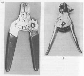
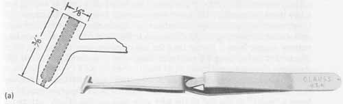
To determine the AWG wire size of either solid or stranded wire, a wire gauge, such as that shown in FIG. la, may be used. Each slot in the gauge is accompanied by the corresponding AWG number size and a relief hole having a diameter greater than the slot width. The purpose of the relief hole is to allow for proper measurement “feel” and also for damage-free removal of the wire from the gauge after measurement. The proper method of positioning the gauge and wire to be measured is shown in FIG. 1b. Notice from the figure that when measuring stranded wire, the insulation is not completely removed as it is for solid wire. Rather, a section of insulation is separated to expose the conductor. This section should not initially be cut closer than 1 inch from the end of the wire to prevent the individual strands from separating or flattening as the wire is placed in the gauge. When removing the section of insulation, the underlying wires must not be twisted, for the diameter of the conductor would be altered and an erroneous reading would result.
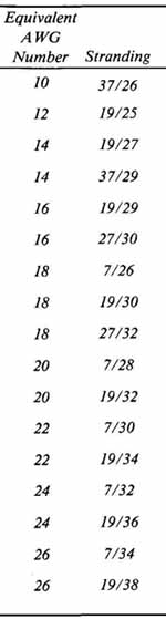
--- TABLE 1 Stranded-Wire Configurations to AWG Numbers
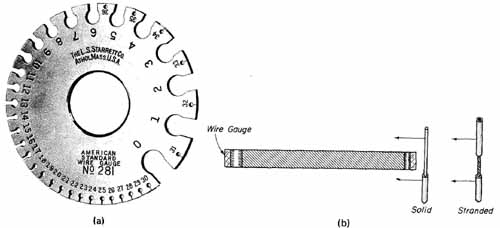
--- FIG.—1 Wire gauge and measuring technique: (a) wire gauge to measure AWG
sizes from No. 0 to No. 36, courtesy of the L.S. Starrett Company, Athol,
Mass.; (b) perpendicular gauge and wire positioning for accurate measurement
in gauge slot.
When measuring stranded wire, the wire gauge reading will be slightly larger than the corresponding AWG number for solid wire because of the slight increase in diameter caused by the spaces between strands. Therefore, when measuring stranded wire, the gauge slot into which the wire fits will be one AWG number less than the actual size and will also yield an odd-numbered AWG value. For example, a stranded AWG No. 20 wire will properly fit into the gauge slot marked AWG No. 19. Therefore, this rule of thumb indicates that the correct size of this wire is AWG No. 20. (It may be well to emphasize at this point that odd AWG number sizes are not commonly stocked and, for this reason, should not be specified.) An optional method of measuring stranded wire is to measure one strand in the gauge, count the number of strands in the total conductor, and refer to TABLE 1 to determine the equivalent AWG number.
To provide additional help in selecting wire, we will use the stereo amplifier to determine the most suitable type of wire plating, type (stranded versus solid), and size.
Example: Power amplifier requirements:
Current: 1.6.amperes dc maximum
Operating temperature range: 70°C (see Sec.2)
Flexibility requirements: pc board is rigidly supported—no vibration problems—minimum flexibility required for assembly
Solution: Since flexibility is not a prime factor, solid wire is selected be cause it is the least expensive. The temperature requirements are minimal, thus allowing for the use of tin coating that will further reduce costs and ensure availability. The size of the wire will now be selected based on the current requirements of the circuit. Most of the interconnections are signal lines in which current demands are very low. The only wires that will be expected to handle 1.6 amperes are those originating from the power supply and feeding the amplifier boards. These wires are specifically the dc power lines Vcc (L) and Vcc (R), and the ground lines. AWG No. 20 wire will handle 2 amperes. All signal wires could be a great deal smaller than this; but for the sake of uniformity and simplicity, a realistic choice would be AWG No. 20 wire for all interconnections. Although the cost of wire is proportional to size, the savings realized by the choice of a smaller wire are negligible.
2. INSULATION MATERIAL
Hook-up wire used in making interconnections in electronic equipment must be provided with an insulation to prevent short circuits and to protect the conductor. The only exception to this rule involves the use of bus wire, which because of rigidity and short length, poses no insulation problems.
The selection of the most suitable insulation for a specific application is based on three criteria: electrical, mechanical, and environmental. Each of these criteria will be discussed.
Common wire insulations and insulation coatings are divided into three main categories: rubbers, vinyls, and special high-temperature or special-application materials. A comparative tabulation of various insulating materials is given in TABLE 2. This table compares the following mechanical and physical properties:
1. Voltage breakdown
2. Insulation resistance
3. Low dissipation factor
4. Abrasion resistance
5. Flexibility
6. Cut-through resistance
7. Water absorption resistance
8. Flame resistance
9. Acid resistance
10. Useful temperature range
The voltage breakdown and insulation resistance are the two factors that are of key importance in high-voltage applications. Insulations designated Excellent are the only ones that should be considered for this purpose. As seen from TABLE 2, silicone, polyethylene (PE), and Mylar possess high corona resistance and are commonly used for high-voltage cables. Neoprene, urethane, and nylon insulations would not be suitable for this application because of their poor rating. The amount of vibration that a wire is exposed to is directly related to its insulation voltage breakdown rating. Therefore, this factor needs to be considered in the choice of insulation.
Signal attenuation at high frequencies is a function of the insulation’s dissipation factor. Generally, insulations with a low dissipation factor are preferable. Teflon has the lowest dissipation factor among those listed in TABLE 2.
Mechanical considerations, such as abrasion resistance, flexibility, and cut-through resistance, represent a compromise between cost versus installation ease. Abrasion and cut-through resistance are generally directly related—the higher the value of one, the higher the value of the other. Of the insulations listed in TABLE 2, Kynar is the toughest, having excellent abrasion and cut- through resistance characteristics. The insulation flexibility becomes an extremely important consideration, especially in high-density packaging for ease of installation. The rubber family (silicon, neoprene, and butyl) exhibits the highest flexibility and the vinyls (PE and poly) the lowest.
Water-absorption resistance is an environmental consideration. Rubber and urethane materials are more susceptible to moisture than the vinyl materials. Teflon materials are the least susceptible to water absorption.
Flame-resistant materials find application in electronic equipment in which explosions or flammable conditions may be encountered. Teflon and Kel F are the materials specified for this application, since they do not support combustion. All the other insulation materials listed in TABLE 2 will support combustion in varying degrees.
Insulations that are highly acid resistant, such as butyl rubber, polypropylene, and Teflon, find wide application in the space industry. Urethane, nylon, and silicone rubber are inferior in this property.
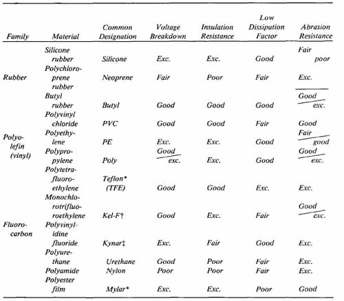
--- TABLE 2 Comparative Ratings for Wire Insulation
*Total number of insulation characteristics that do not meet minimum required ratings. Insulation characteristic meets minimum required rating. Insulation characteristic below example problem minimum required rating. ---
The useful temperature range for PVC, nylon, and PE is narrow, whereas for Teflon and Kel-F it is wide. In considering this property, it is important to use good judgment in terms of cost. For example, it would not be advisable to choose Teflon (upper limit 250°C) based on its superior temperature characteristics if the temperature range of PE (upper limit of 80°C), as well as its other characteristics, will satisfy the design requirements because Teflon is consider ably more expensive.
From the wide range of materials available, it is evident that the selection of the most appropriate wire insulation for a specific application is a compromise between specifications and cost.
To illustrate the use of TABLE 2, the following problem is considered:
Circuit: stereo power amplifier
Electrical specifications
Voltage 36 volts dc maximum
Current 1.6 amperes dc maximum
Frequency 20 to 20 kilohertz (kHz)
Mechanical specifications
Stationary
No expected high-level vibrations
Low-density packaging
All leads pass through grommets
Environmental specifications
Temperature range +50 to 90°F (+ 10 to 32°C)
Humidity 40% typical
These specifications appear to present no critical circuit requirements insofar as wire insulation selection is concerned. Since voltage and current requirements are low, any insulation with a voltage breakdown and insulation resistance comparison rating of good and excellent is acceptable. This stipulation eliminates neoprene, Kynar, urethane, and nylon from further consideration.
With a frequency range specified at 20 hertz to 20 kHz, any insulation with a dissipation factor rating of good and excellent will be suitable. Low-dissipation-loss factors become critical only at higher frequencies.
Because all wires will be passed through rubber grommets, the possibility of abrasion is nonexistent and the quality of abrasion resistance need not be considered in this evaluation even if a fair or poor rating is assigned a specific material. Therefore, for this consideration, any of the wire insulations listed are suitable.
Flexibility also is not critical because of the low-density packaging of the circuit and the resultant uncomplicated wiring. Therefore, no insulation material need be rejected because of its flexibility rating.
To reduce assembly time, especially if large-scale production is considered, an insulation with a comparison rating for cut-through resistance of good or excellent should be considered. This eliminates silicone, butyl, and Teflon from further consideration.
Since the use of this type of power amplifier is usually in the home or other location wherein temperature and humidity are controlled at levels that exclude critical environmental problems, any insulation with a water-absorption resistance rating of good or excellent is acceptable.
Flame and acid resistance is, of course, of no consideration in the intended environment. Therefore, no insulation, even with a fair rating for either of these categories, is omitted from consideration.
Finally, the expected ambient temperature of the unit is approximately + 10 to 32°C, with a factor of 2 used in derating on each end of the temperature range to allow for extreme conditions (the inside case temperature will increase under full power output). The range of derated temperatures now considered becomes 5 to 64°C. TABLE 2 shows that all the insulations listed have useful temperature ranges that are well within these specifications. As a result, no insulation material will be eliminated because of temperature limitations.
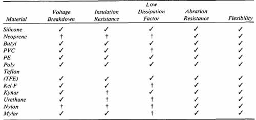
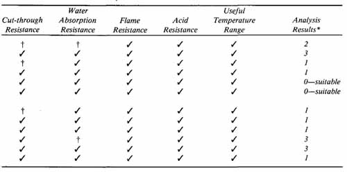
--- TABLE 3 Sample Evaluation Chart for the Selection of Wire Insulation
An evaluation chart is provided in TABLE 3 to show more clearly the procedure for eliminating insulation materials that are below minimum ratings. The Analysis Results column of TABLE 3 indicates that either polyethylene (PE) or polypropylene (poly) plastic vinyl insulation is suitable for the example problem. The final selection between these two materials now becomes a matter of cost and availability.
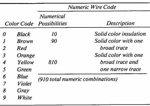
For purposes of identification, hook-up wire insulation is provided with a color code. This provides for rapid identification of wires, which is an indispensible aid when working with cables and harnesses. Color-coding is extremely useful in both assembly and in troubleshooting. Military and industrial standards have been established for color-coding insulation. These standards are listed in TABLE 4. Similar to the resistance color code adopted from EIA (Electronic Industries Association) standards, the solid color of the insulation is designated by numbers 0 through 9 and represents the first digit of the color- code number. With 10 basic colors, 10 numerical possibilities are available to identify individual wires. For complex wiring involving more than 10 leads that must be identified, insulation is also available with a broad tracer band that is a different color from the body color and spirals the length of the wire. These tracer colors now extend the available different color combinations to 100. When more than 100 wires are involved, as in the case of complex harnesses, insulation is available with a second tracer that is narrower than the first. Both tracers are closely spaced, running parallel with each other, and spiral the en tire length of the wire. The use of the second tracer extends the numerical coding capabilities to 910 possible combinations. To illustrate the numbering system, a wire with a red body color, broad green tracer, and narrow orange tracer (red/green/orange) can be classified by the three-digit number 253.
--- TABLE 4 Color-Coding Standards for Wire Insulation
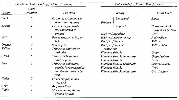
--- TABLE 5 Wire Color Identification Related to Circuit Function
Standards also have been established that do not employ a numbering system but rather designate wire color with respect to circuit function. Two such standards are the Government Standard MIL-STD-122 color code for chassis wiring and the ETA color code for power transformers. These classifications are shown in TABLE 5.
3. SPECIAL WIRE CONFIGURATIONS
There are several readily available wire configurations that are used for special applications. Shielded wire, shown in FIG. 2a, is a variation of hook-up wire previously discussed. It consists of an insulated length of hook-up wire en closed in a conductive envelope in the form of a braided wire shield. The shield is formed from fine strands of tinned, annealed copper wire. The strands are woven into a braid that provides approximately 85% coverage of the underlying insulated conductor. Shielded wire is also available with an outer insulation covering to prevent shorts when running the wire between termination points. Another variation of shielded wire has two inner conductors twisted around each other. This twist improves unwanted signal cancellation.
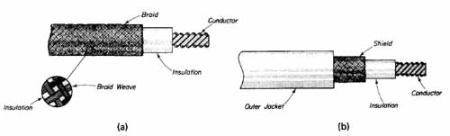
--- FIG.—2 (a) Shielded wire; (b) coaxial cable.
Shielded wire is employed in audio circuits at the input stage where the signal level is low and undesired noise (typically 60-hertz hum) or feedback from the output stage of a high-gain amplifier could produce unwanted signals. The shield is either connected to the chassis at the circuit input or it may be connected to the chassis at both ends to provide the most effective method of minimizing undesired signal pickup.
Coaxial cable (coax), shown in FIG. 2b, is used exclusively in RF circuits. It is similar in construction to shielded wire, with the outer insulating jacket isolating the shield from ground. The major difference between coaxial cable and shielded wire is in their electrical characteristics. Coax is designed specifically to transmit RF energy, from one point to another, with minimum loss (attenuation). Insulation material and thickness is controlled with extreme accuracy during manufacture to produce cables possessing 50, 75, or 95 ohms characteristic impedance for proper matching. Shielded wire, on the other hand, is intended for low-frequency applications in which its impedance is not critical.
Losses from skin effect at high frequencies must be minimized when using coaxial cable. Skin effect is the term used to describe the type of loss or attenuation of the signal caused by the current traveling along the surface (skin) of the conductor and partly into the adjacent insulation. Because of its outstanding insulating characteristics at high frequencies, nylon is the type of insulation most often used in the manufacture of coaxial cables.
Another special wire configuration is Litzendraht (Litz) wire, which is used in the manufacture of tuning coils. At short-wave frequencies, this type of wire has low skin effect, owing to its configuration. Litz wire is a stranded conductor containing 25 or more extremely fine wire strands. Each strand is independently insulated with cotton insulation and wound from the center to the outer surface of the overall conductor. This technique of winding tends to equalize the skin effect problem.
4. TOOLS FOR WIRE PREPARATION AND ASSEMBLY
To form a sound electrical connection between the hook-up wire used for inter connections and the terminal to which it is to be soldered, all insulation must be completely removed from the end of the wire to expose the conductor. In addition, it may become necessary to remove contaminants, such as dirt, finger oils, or oxidation, from the bare wire. (Oxidation will occur if the bare conductor has been exposed to the atmosphere for a prolonged time before soldering.) It is vitally important when preparing to make a solder connection that all surfaces to be soldered (alloyed) are absolutely free of all contaminants.
--- FIG.—3 Mechanical wire strippers: (a) step adjustable; (b) adjustable.
Mechanical wire strippers, such as the two styles shown in FIG. 3, are among the most common tools used to remove wire insulation. Each has its advantages and disadvantages with regard to resulting quality and ease of operation.
The step-adjustable stripper is shown in FIG. 3a, All that is required to set the jaws is to rotate the selector step wheel until the desired gauge number is oriented with the stop pin. Its obvious disadvantage is that it is capable of stripping only eight gauge wire sizes (AWG No. 12 to AWG No. 26). To minimize the possibility of conductor damage when using this stripper, it should be held perpendicular to the wire when pulling off the insulation.
The most popular mechanical stripper is the automatic style shown in FIG. 3b and being used in FIG. 4. This stripper has six marked cutting positions on the jaws to accommodate various gauge sizes. The wire to be stripped is placed into the appropriate cutting jaw position and between the gripping jaws. With the wire held in position, the handles are gently squeezed together. This causes the movable upper cutting jaws to first press the insulation down into the lower stationary cutting jaws. Additional squeezing of the handles causes the insulation to be severed about the conductor while the upper movable gripping jaw firmly grasps the wire with the lower stationary gripping jaw. Further squeezing of the handle causes both sets of jaws, while engaged, to separate, thereby removing the insulation from the end of the wire (FIG. 4). As pressure on the handles is removed, both sets of jaws disengage, thus releasing the stripped wire. These strippers are also available with a stop that, when set to the desired length of strip, will consistently remove the same length of insulation from wires.
---FIG.—4 Insulation removal with mechanical wire strippers.
Thermal wire strippers, although not popular in prototype construction, are another means of removing the insulation from wires. They consist of a heating element and two pivoted handle grips having electrodes that serve as the stripping jaws. The wire to be stripped is positioned between the electrodes, which are then clamped together around the wire. Squeezing the insulated handles activates a switch that causes the electrodes to heat the insulation to its melting point. With the electrodes energized, the wire is rotated so that the insulation melts uniformly. When the insulation has melted, the pressure on the handles is released, the wire is removed, and the insulation is pulled off of the conductor. Thermal strippers will not nick or cut conductors. They are more expensive than mechanical strippers, however, and may also cause irritating fumes as the insulation is melted.
Whichever method of wire stripping is employed, more wire than is necessary to make the connection should be stripped. The reasons for this are (1) in the case of stranded wire where tinning (discussed later in this section) of the strands is required, solder buildup usually occurs at the conductor end and can be removed simply by cutting; and (2) if each wire is cut and stripped to its exact required dimension, this will not provide the necessary “play” that the technician may need to adjust wire positions during wire operations.
As mentioned previously, it may be necessary to further clean the ex posed wire prior to soldering. This can be quickly accomplished with the use of the lead cleaner shown in FIG. Designed primarily for use on solid wire (including component leads), this eraser-style cleaner will remove contaminants such as dirt and oxides from the surface of the wire. A component lead being cleaned is shown in FIG. 5.
To strip enamel or any type of film insulation from solid wire, an abrasive lead cleaner may be used. It is made of braided wire formed about a piece of aluminum. Details for constructing this type of cleaner are given in Exercise 25.1.
The final step prior to interconnection is the tinning of stranded wire. This process is necessary to allow for the formation around a terminal in a manner that will result in as neat a joint as obtainable with the use of solid wire. Approximately inch of insulation is first removed from the wire and the individual strands are firmly twisted together in a direction to return to their original twist orientation that is disturbed by the stripping action. This twisting also returns the wire to its original diameter, which is important to avoid difficulties in making connections to small eyelet terminals, pot-type terminals, or the center prong on phono plugs.
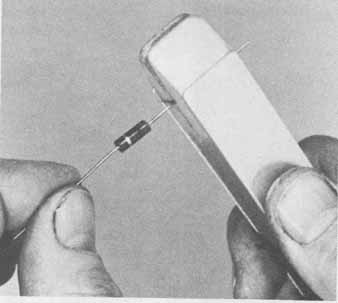
--- FIG.—5 Lead and wire cleaning.
The exposed and twisted wire is then dipped into a liquid flux such as Kester 1544 or 1589 flux. Allowing the flux to contact the insulation should be avoided so that cleaning up after the tinning process has been completed will be faster.
The tinning of stranded wire can be effectively accomplished using one of two methods. The first is with the use of a soldering iron as shown in FIG. 6a. The insulated portion of the wire is gently held between the jaws of a bench vise with the fluxed conductor extended. The hot soldering iron is brought into con tact with the bottom of the wire and the solder applied to the top directly onto the strands. Heat from the iron will cause the solder to melt and be drawn through the strands since melting solder follows the direction of heat flow. Drawing the iron and the solder along the length of the wire from the end to the insulation and back again will ensure solid, uniform bonding of the individual strands.
The second method of tinning is with the use of a solder pot. This is shown in FIG. 6b. The pot contains a pool of molten solder maintained at a temperature between 600 and 650°F. To begin the tinning process, the dross formation on the surface of the molten solder is skimmed away with a small wooden spatula such as a tongue depressor. The fluxed wire is then slowly placed into the solder so that the insulation is just above the surface. This slow entry al lows the individual strands to arrive at a sufficient temperature so that proper wetting action and bonding results. When withdrawing the wire, again it is done slowly so that the surface tension of the solder will draw off any excess solder on the wire. (Caution: Safety glasses should be worn when working with molten solder, to avoid injury.)
Effective tinning results when sufficient solder has wetted all conductor surfaces forming a solid bond between them. Excessive solder should be avoided. The contour of each strand should be plainly visible.
After the wire has been tinned, the flux residue should be removed. This is done by placing the wire on a paper towel and scrubbing the end with a stiff acid brush using isopropyl alcohol. The wire is now ready to be wrapped around any type of connection without concern for any strands becoming separated from the group.
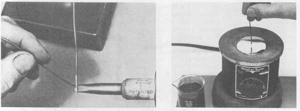
---FIG.—6 Tinning stranded wire: (a) using a soldering iron; (b) dipping the
wire into liquid flux and then into molten solder.
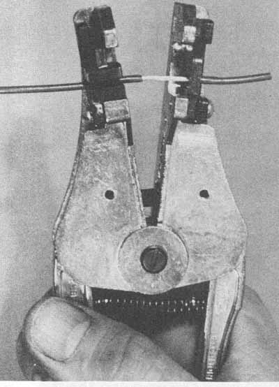
A problem associated with tinning or making soldered connections with stranded wire is a condition termed wicking, which causes solder to flow by capillary action under the insulation. As a result, the wire becomes rigid where the most flexibility is required, thus defeating the purpose of using stranded wire. To minimize this problem, anti-wicking tools (conductor heat sinks) such as the type shown in FIG. 7a are used. The handles are first squeezed to open the jaws to accept the conductor and insulation (FIG. 7b). The tool is then moved so that each jaw nose rests firmly against the conductor adjacent to the insulation. The anti-wicking tool protects the insulation from the heat of the soldering iron by shunting the flow of heat from the conductor as it passes into the insulation, thereby reducing wicking.
--- FIG.—7 Use of anti-wicking tool: (a) anti wicking tool; (b) wire insertion.
--- FIG.—8 Various styles of wire-cutting tools.
After the tinning operation, the excess wire length along with the accumulation of solder that usually builds up at the wire end can be removed with a pair of diagonal cutters. Selecting the most suitable type of diagonal cutters (dykes) depends primarily on the size of the wire being used as well as accessibility during assembly. Because of the variety of cutting situations encountered, many styles of diagonal cutters are available. A selection of common styles used for electronic wiring is shown in FIG. 8. The size of these diagonal cutters ranges from 6 inches long for heavy-gauge wire (AWG No. 14 maxi mum) to 4 inches long for use with smaller wire such as AWG No. 24 and smaller.
The cutting edges of the diagonal cutters can be classified as regular, semi-flush, or full-flush. Regular cutters, used for general-purpose applications, leave a “point” at the end of the wire after cutting. Semi-flush cutters leave a less pronounced point. Full-flush cutters, intended for use only on annealed copper wire leave no point or chamfer but rather a smooth, flat end perpendicular to the wire axis. Since the regular and semi-flush cutters distort the end of a conductor, this could create a problem when attempting to insert the wire into a close tolerance hole such as those associated with pot-type terminals, small eyelets, and holes in pc board terminal pads. In addition, the sharp points these cutters leave are undesirable when protruding from terminal connections. For these reasons, the full-flush cutter is recommended.
The jaws of most diagonal cutters produce a slight “shock” as they come together when cutting a wire. When used on hook-up wire, this presents no problem. However, sensitive semiconductor devices could be damaged by this shock. For this reason, shear-type cutters are recommended for delicate work. The jaws of these cutters pass each other similar to a pair of scissors, thereby minimizing the cutting shock.
Diagonal cutters are available in rounded, tapered, and offset noses to fulfill the requirements of a variety of cutting needs. The most appropriate cutting jaws, shapes, and edge types are selected after the work to be performed is evaluated. When heavier-gauge wires are to be cut and close cutting tolerances and accessibility are not critical, less delicate cutters may be employed. Intricate wiring using finer-gauge wire will require more delicate cutters.
Rubber jaw inserts are available on some styles of cutters, which grip the end of the wire to be removed. These inserts prevent the cut end from flying out of the jaw when the wire is cut. There is a serious safety hazard involved in using diagonal cutters not equipped with rubber inserts. It is always a good practice to point the conductor end downward to prevent the flying end from causing injury. Cutters with plastic grips are preferable to cutters with no grips because they not only provide more positive gripping, but also reduce hand fatigue.