AMAZON multi-meters discounts AMAZON oscilloscope discounts
LEARNING OBJECTIVES:
Upon studying this section on chassis hardware and component assembly, the student should be able to:
1. Be familiar with the order in which parts and hardware are assembled.
2. Know the various types of machine screws, nuts, washers, and thread- forming and thread-cutting screws.
3. Use the following tools for assembling parts to a chassis:
a. Screwdrivers
b. Nutdrivers
c. Wrenches
d. Pop rivet guns
e. Pliers
f. Taps and dies
4. Be familiar with the various types of special fasteners and hardware used in chassis assembly.
0. INTRODUCTION
With the completion of all subassemblies (the pc boards in the amplifier project), the assembly of hardware and components onto the main chassis element may begin. In addition to the boards, this involves the mechanical securing of jacks, connectors, fuse holders, terminal strips, switches, potentiometers, lamps, meters, power cords, and transformers.
Before beginning to assemble parts, the overall task should be examined. If there are few components and parts to be assembled and if they are small, random mounting will pose no particular problem. If, however, the assembly involves many component parts with a wide range of sizes and weights, some order will be necessary to minimize needless effort and reduce the possibility of damaging delicate components.
Small, sturdy components such as fuse holders, terminal strips, lugs, grommets, and connectors should be mounted first. Transformers, filter chokes, and other large or bulky components should be among the last to be mounted, to avoid having to work with a heavy, bulky chassis during the initial assembly phase. Fragile components such as lamps, meters, sensitive relays, and pc boards should be the last to be mounted. As working space diminishes with the addition of components, extreme care must be exercised to avoid dam aging parts with assembly tools.
Mounting electronic components and hardware to a metal chassis may appear to be a simple task. However, efficient and quality workmanship will result only if the four major factors of packaging are considered. These are (1) mechanical security, (2) appearance, (3) accessibility, and (4) cost. Each factor is discussed in this section in conjunction with specific information on common and special fastening devices. Also considered are correct tool selection and assembly techniques for securing components and hardware.
1. MACHINE SCREWS
Machine screws are among the most common types of fasteners used in electronic packaging since they provide sound mechanical security and are easy to assemble and remove. Machine screws are designated by (1) head style, (1) drive configuration, (3) diameter, (4) threads, (5) length, (8) material, (7) finish, and (8) fit.
Some of the common head configurations are the fluster, binder, pan, round, flat, oval and truss styles. These are shown in FIG. la.’ Although somewhat of a personal preference, the head style selected is generally deter mined by appearance, application, and mechanical security. Fillister, binder, and pan heads are usually preferred over round heads for appearance sake. These head styles are mechanically superior to the round head because there is more material at the driver blade pressure points. These head styles have approximately the same-size sealing plane (surface contact area) for a particular screw size, although the fillister style has the smallest head diameter. Both the flat and oval heads require that the work surfaces be countersunk prior to assembly. The flat head is used for flush mounting and has sealing plane angles of 82 or 100 degrees. Neither the flat nor the oval heads are recommended for use with thin sheet metal, wherein countersinking might weaken the assembly. The oval head is often used with a cup-style washer for securing control panels to racks. Countersinking in this case is unnecessary since the shape of the washer provides the required seating. This arrangement tends to provide both a decorative appearance as well as excellent mechanical security. The truss head style, common to sheet metal screws, has a larger sealing plane that provides greater surface contact area with the work.
The drive configuration refers to the style of head for tool access. Those most common to electronic assemblies are the (1) slotted, (2) Phillips, and (3) hexagonal socket or Allen design. These are shown in FIG. lb. the slotted style is the most widely used. The Phillips head has the advantage over the slotted type in that it provides four positive-drive pressure points completely within the perimeter of the head. It is often used when the screw is visually obstructed during assembly, since it allows the screwdriver to be self-aligned. In addition, the recessed style of the Phillips head greatly reduces the possibility of the driver slipping from the screw head, which could damage the work surface. The Allen configuration allows for even more positive tool positioning and gripping and is commonly used on set screws for securing knobs to control shafts. Other less common drive configurations that may be encountered are shown in FIG. 1c. Each of these requires special driving tools. The various driving tools common to electronic assembly will be discussed in Sec. 4.
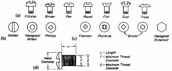
--- FIG.—1 Machine screw styles and drives: (a) machine screw head styles;
(b) head-style drive configurations; (c) drive configurations requiring
special driving tools; (d) machine screw thread measurements.
The maximum thread diameter (dimension G in FIG. 1d) varies from 0.086 to 0.216 inch for general electronic assembly. The minimum diameter, shown as dimension Tin FIG. ld, will vary from 0.0628 to 0.1619 inch. Small sizes of machine screws are generally designated by gauge number. For the thread diameters referred to, the gauge numbers vary from No. 2, having a diameter of 0.086 inch, to No. 12, having a diameter of 0.2 16 inch. Larger thread diameters are given in fractions of an inch. Smaller-diameter screws, with gauge numbers of 1 or 0, are not common in electronic assembly. A listing of some common thread gauge numbers together with their decimal equivalents is shown in TABLE 1. A more complete listing is provided in Appendix V. One way of determining the gauge number for an unknown screw size is simply to measure the thread diameter with a micrometer and compare the reading thus obtained with the corresponding gauge number of TABLE 1.
Machine screws are manufactured with right- and left-hand threads. Right-hand threads are secured by clockwise (cw) rotation and extracted by counterclockwise (ccw) rotation. Left-hand threads are rotated in the opposite directions and are used only in special cases wherein vibration or rotation of the system would tend to loosen the conventional right-hand thread.
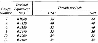
--- TABLE 1 Machine Screw Sizes Most Frequently Used in Electronics
---
Machine screws are also designated by the number of threads per inch. The simplest method of determining this is by placing a scale against the threads and counting the number of threads in 1 inch. For a particular screw gauge or diameter, the number of threads per inch will depend on the screw thread system used. Although there are other systems of screw designations, machine screws having either Unified Coarse (UNC) or Unified Fine (UNF) designations are predominantly used for electronic assembly. Referring to TABLE 1, a UNC screw having a gauge No. 4 diameter has 40 threads per inch, whereas a UNF screw with the same gauge number has 48 threads per inch. It is apparent that the UNC system has fewer threads per inch than the UNF system. The coarseness of the screw selected will depend on its application. Generally, UNC threads are preferable for rapid assembly since thread meshing is a less exacting process. This coarser screw is also used when threading into soft material. Since a machine screw of a given size with a coarse thread has a smaller minimum diameter than the fine thread, it will mesh deeper into the material surrounding the tapped hole. This advantage greatly reduces the possibility of thread shearing when an axial load is placed on the screw. If vibrations are a consideration, fine threads are preferable. Because of their greater minimum diameter, they can be torqued more than comparably sized coarse thread screws and will not shake loose as readily.
For all head styles except the flat and oval designs, the thread length is measured from the sealing plane to the end of the screw (FIG. 1d). Flat-style and oval-style screw lengths are measured from the top of the sealing plane to the end. Screw lengths between 1/8 and 5/8 inch are available in increments of inch. Lengths from 5/8 to 1.25 inches are graduated in 1/4-inch increments, whereas those from 1.25 to 3 inches are graduated in 0.25 inch increments.
Screws for electronic assembly are made from steed brass, aluminum, or insulating materials such as nylon. The finishes available include black anodizing, cadmium, nicked zinc, or chrome platings. The finish selected will depend on the appearance and the necessary corrosion protection.
Screws are also designated with a specific relationship (fit) between mating threads of nuts or tapped holes and machine screws. There are four classes of fit between threaded parts: Class 1 is an extremely loose fit with considerable “play” between the threaded parts; Class 2, sometimes designated as a “free fit,” can be readily assembled with finger pressure; Class 3 has more of a snug fit than Class 2 but requires only finger pressure for initial assembly; Class 4 is characterized by the tightest available fit, requiring screwdrivers and wrenches for assembly of the threaded parts. Selecting the most appropriate class of fit will depend on such factors as (1) speed of assembly, (2) type and style of washer employed, and (3) the amount of looseness between threaded parts that can be tolerated. For most electronic applications, the Class 2 fit is standard.
Machine screws may be completely identified by the following abbreviated description:
#6-40 x 3/8 UNF—2A LH Pan Hd. Steel C.P.
An explanation of this example follows:
#6—major thread diameter (equivalent to 0.138 inch, refer to TABLE 1).
40—number of threads per inch.
3/8—length of thread in inches measured from the sealing plane to the screw end.
UNF—type of thread (Unified Fine). If the type was UNC, this designation would normally be omitted and assumed to be understood.
2A—the 2 represents the class of fit between threaded parts and the A designates that the thread is external. A B suffix designates an internal-type thread for machine nuts.
LH—left-hand thread. If a right-hand was specified, no designation is given since it is assumed to be understood.
Pan Hd.—head style.
Steel—material.
C.P.—plating (cadmium-plated).
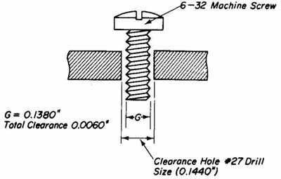
--- FIG.—2 Clearance hole for a 6-32 machine screw.
Clearance hole sizes for several machine screws are given in Appendix VI. The clearance hole size is determined by the maximum diameter of the screw thread. This type of hole is drilled when components and hardware are to be assembled with screws and nuts. The diameter of a clearance hole must be sufficiently larger than the thread diameter to allow complete unobstructed pas sage of the screw through the hole. The amount of clearance will depend on the materials to be fastened. However, the values given in Appendix VI are average sizes, which are satisfactory for most applications. A clearance hole together with its tolerance is shown in FIG. 2
2. NUTS AND WASHERS
Nuts used with machine screws are designated by (1) style, (2) chamfer, (3) hole diameter and threads, (4) fit, (5) material, (6) finish, (7) width, and (8) thickness. Nuts common to electronic assembly are shown in FIG. 3a. The hexagonal style is by far the most widely used and is generally preferable to the square nut for reasons of appearance and ease of assembly. This nut may have single chamfer, double chamfer, or single chamfer and washer face (FIG. 3b). When a single chamfer nut is used, the flat side should be against the work to provide the best appearance with no exposed sharp edges. If the work surface is finished, double chamfer or washer face nuts should be used. When tightening the nut against the work surface, the chamfer or washer face will prevent any visible surface marring, such as the circular abrasions formed by the points of a single chamfer square or hexagonal nut.
The hole diameter and thread type are, naturally, consistent with the mating screw. This is also true for class of fit, material, and finish. For each size and style of nut, different widths (measured across pairs of opposite flats) and thicknesses are available. These external dimensions are shown in FIG. 3c. Tabulated sizes for common hexagonal nuts are given in Appendix VII. Nuts with larger widths are normally used for ease of handling and rapid assembly, whereas those with smaller widths are selected if there is a possibility of interference with other hardware or if assembly clearance is limited.
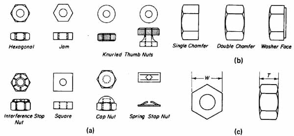
--- FIG.—3 Machine screw nuts and fasteners: (a) nuts common to electronic
assembly; (b) hexagonal nut face styles; (c) width and thickness measurements
for hexagonal nuts.
The special-purpose nuts, also shown in FIG. 3a, have styles that dictate their application. A description and application of each follows:
Jam nut: basically the same as a hexagonal nut except that it is from to inch thinner, depending on the hole diameter. This nut may be used alone but it is more often employed under a regular hexagonal nut for a more secure assembly. When this nut is tightened, its flats align with those of the hexagonal nut, providing the desired locking action.
Interference stop nut: used to prevent loosening due to vibration. It has an internal unthreaded plastic or fiber collar. When the nut is tightened, the screw threads are forced into the inside surface of this tapered collar. Being elastically deformed, the collar squeezes against the screw threads, providing a secure locking action and eliminating the need for a lock washer.
Square nut: often used in securing channel stock in steel cabinets or racks. The flat of the nut often fits snugly or jams against the inside member when being tightened, thus requiring merely a screwdriver for assembly.
Knurled thumb nut: allows for quick finger tightening. It is commonly used on terminal posts such as those on some primary cells and telephone terminal blocks.
Cap nut: used primarily for purposes of appearance. It completely covers the end of the screw and its shape eliminates sharp corners or edges. Chrome-plated cap nuts add a decorative appearance to a cabinet.
Spring stop nut (speed nut): pressed onto the screw with only minimal final tightening required. It is self-retaining as well as self-locking. Be cause it greatly reduces assembly line operations, the speed nut is often used in radio and television receivers. It may also be used to secure smooth studs or tubing.
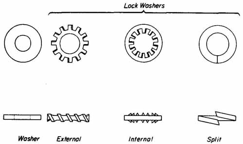
--- FIG.—4 Washer styles. Washer, External, Internal, Split
Washers are classified as either flat or lock type (FIG. 4). Flat washers are used in contact with a screw head or the chamfer of a nut to provide more surface area to distribute the forces imposed on the screw and nut. Lock washers are used to secure square or hexagonal nuts from loosening due to vibrations or handling. For electronic assembly, the tooth-type lockwasher is used extensively since it provides maximum gripping action. Normally, the use of one lock washer is sufficient. However, under severe vibrations lock washers should be placed under both the nut and screw head. The tooth-type lock washer should not be reused when removed. The gripping edges of the teeth are easily dulled and the spring action becomes fatigued. These washers have from 10 to 24 combined points of contact, depending on the number of teeth. Internal tooth washers are preferred over the external type from the standpoint of appearance since they cause no visible surface marring when assembling components such as the potentiometer shown in FIG. 5a. External tooth washers are generally used with flat washers for mounting components having over sized clearance holes. This arrangement is shown in Fig 5b.
The spring-type or split lock washer, also shown in FIG. 4, uses the tem per of the steel to maintain locking action. As the washer is compressed, the spring tension exerts a force that prevents counter-rotation. This type of washer is less effective than the tooth type because the locking action results only from spring tension. Flat steel washers are used in conjunction with tooth- type lock washers when securing soft materials, whereas resilient washers, such as lead or fiber, are used to provide a cushion effect when assembling brittle material.
The inside diameter of a washer must coincide with the clearance hole diameter of the screw with which it is associated. The outside diameter will depend on the application. Recommended washer sizes are given.
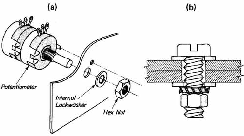
--- FIG.—5 Washer assembly techniques: (a) washer assembly for potentiometer
mounting; (b) washer assembly for oversized clearance holes.
3. THREAD-FORMING AND THREAD-CUTTING SCREWS
Thread-forming and thread-cutting screws are widely employed when the use of nuts or the tapping of machine threads is not practical. These screws do not require a pre-threaded hole for fastening. Manufactured from hardened steel, they form or cut their own threads as they are turned and driven into a hole. They cannot be driven into a material harder than their own. These screws are available in slotted, hexagonal, and Phillips drives with head styles common to machine screws, in addition to the washer head style shown in FIG. 7. Three of the popular thread designs are shown in FIG. 6. These are the sheet metal (thread forming), machine screw thread forming, and self-tapping (thread cut ting) types. The sheet metal screw, shown in FIG. 6a, when forced into the proper-sized predrilled hole, will form the metal around the hole into a threaded shape matching its own thread. This screw has a widely spaced thread extending to a point. The machine screw thread-forming type, shown in FIG. 6b, has a slightly tapered end but does not extend to a point. It has standard machine screws threads, which require greater force to drive than a sheet metal screw. This screw is used in place of the sheet metal screw when the possibility of loosening from vibration exists. The self-tapping screw, shown in Fig 23.6c, has one or more slots in the threaded end for chip relief. As this screw is driven into a hole, it cuts threads in basically the same manner as a tap. (Taps are discussed in Sec. 23.8) The self-tapping screw is not used on sheet metal but is intended for fastenings to castings and soft materials such as Bakelite, copper, aluminum, and plexiglass.
Sizes of thread-forming and thread-cutting screws are similar to those for machine screws. To result in optimum mechanical security, the size of the pre drilled hole is important. The size of this hole will depend on the screw size, gauge of the meta4 and type of metal. Generally, for the same size screw, a larger hole must be provided in harder materials. For example, if a No. 6 self- tapping screw is to be used to secure sheet metal whose thickness is 0.060 inch, a No. 32 drill bit is recommended for steel, whereas a No. 36 would be necessary for aluminum. Information on hole sizes for thread-forming and thread-cutting screws is provided in TABLE 2.
Thread-forming and thread-cutting screws do not provide the mechanical security obtainable with machine screws with lock washers and nuts. However, when vibration is not a factor, they overcome accessibility problems in areas where nuts cannot be installed. Access or cover plates are an example of this application.
The proper securing of two pieces of sheet metal with a sheet metal screw is shown in FIG. 7. The hole drilled in the metal closest to the screw head must be a clearance hole to ensure positive metal-to-metal contact when the threading is completed and the sealing plane of the screw head is flush with the metal. For sheet metal applications, screws with larger sealing planes, such as the washer-head type shown in Fig. 7, should be used.
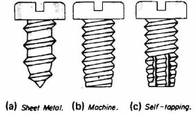
--- FIG.—6 Thread-forming and thread-cutting sheet metal screw styles:
(a) sheet metal; (b) machine; (c) self-tapping.
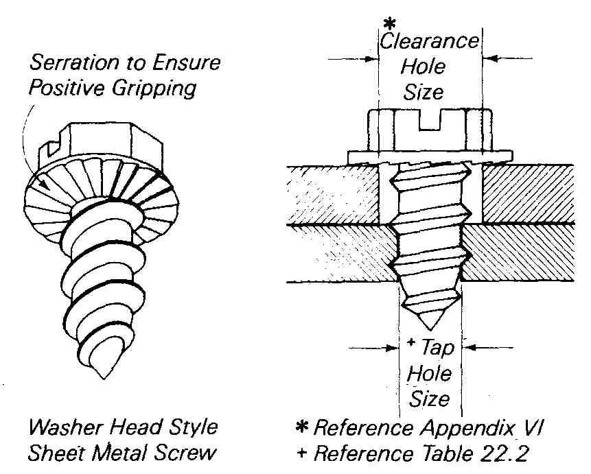
--- FIG.—7 Recommended method for sheet metal assembly.
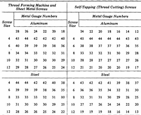
--- TABLE 2 Recommended Drill Sizes for Sheet Metal Screws --- These
drill sizes are intended only as a guide and may vary with application.
4. SCREWDRIVERS AND NUTDRIVERS
Screwdrivers are the most common tools used for securing the screws discussed in Sec. 3, above. They are available in a variety of handles, shank lengths and shapes, and driver styles. A popular-style screwdriver is shown in FIG. 8a together with the nomenclature of its parts. The handle is usually made of hardwood or plastic. In addition, a rubber grip may be provided for additional electrical protection, positive gripping, and comfort. For those screw drivers without a rubber grip, large flutes are formed in the handle for improved gripping. The shank is manufactured from a tempered steel alloy specifically designed to withstand distortion caused by the excessive torque to which these tools are subjected. The handle and shank, however, will not with stand severe forces when the screwdriver is misused, such as for prying or bending. The shank may have either a round or square cross section. The square design is usually found on larger-size screwdrivers, where severe torque is expected. Shank lengths normally vary from 3 to 16 inches. For general electronic assembly, shank lengths up to 10 inches find wide application.
Driver styles are available for all screw-head drive configurations shown in Fig 23db and c. The three most common types are the standard, Phillips, and hexagonal drivers. These are shown in FIG. 8b.
The standard driver has a tapered tip design that fits into the drive slot of a screw head. Common blade widths are , , , , , and inch. When selecting the most suitable screwdriver to avoid damage to the screw or the work surface, the width of the blade should closely match the slot length but should not extend beyond the perimeter of the screw head.
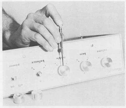
Phillips screwdrivers are designed to fit the tapered cross-slots on screw heads made for this type of drive (FIG. 1b). Since more contact points are available with this design than with the slotted type, more driving force can be applied with less possibility of slippage. This style is commonly available in five number sizes; 0, 1,2, 3, and 4. These will fit a large variety of Phillips screw- head sizes. TABLE 3 shows the screwdriver number and the screw size to which each will accommodate. Those most frequently used in electronic assembly are numbers 1, 2, and 3. This screwdriver must be held in exact alignment with the drive configuration of the screw head to be effective. The Phillips screwdriver properly positioned for use is shown in FIG. 9.
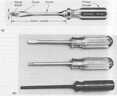
---FIG.—8 Screwdriver styles: (a) screwdriver nomenclature, courtesy
of Stanley Tools; (b) standard, Phillips, and hexagonal drivers.
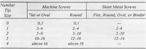
--- TABLE 3 Phillips Screwdriver Selection
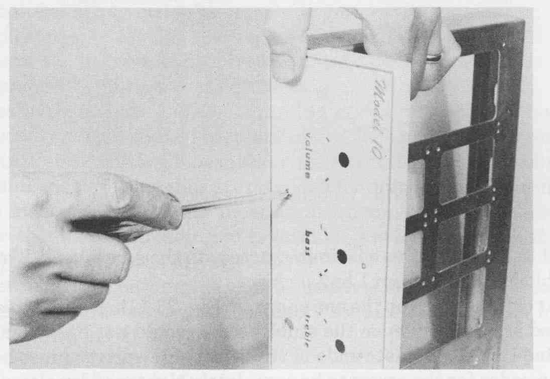
--- FIG.—9 Correct use of the Phillips screwdriver.
The Frearson or Pozidrive (a trade name of Phillips International) styles (see FIG. 1c) are similar to the Phillips drive except that they allow for a much more precise fit between the driver and the screw head. This fit enables the screw to be supported unaided on the end of the driver, which can be a time saving advantage in assembly work in which accessibility is limited.
The Allen drive, as well as the special Bristol type (whose screw heads are shown in FIG. 1), also have a distinct advantage over the slotted style in that they minimize the possibility of the driver slipping out of the screw head and damaging the work surface. The Allen drive is encountered more often in electronics assembly than the Bristol style. A selection of Allen drives from to inch is suitable for most electronic applications. These sizes vary by inch for sizes from to inch, by 4 inch for to inch, and by inch for to inch.
For extremely small set screws, the Bristol drive is often preferable to the Allen style since its multiple spline design prevents rounding of the driving surfaces of either the drive or the screw head through continued use. Bristol drives are available with four or six flutes.
For small and delicate work, jewelers’ screwdriver sets may be used. The barrel of the handle is knurled with a swivel-top finger rest. This configuration allows the driver to be turned using the thumb and forefinger while applying pressure with the index finger (FIG. 10).
Screwdrivers for special applications are shown in FIG. 11 and are available in all the standard drive configurations. The “stubby” design, shown in FIG. lla, is used if there is limited access to the screw head. These drivers are available in lengths from 1 to 2 inches.
--- FIG.—10 Properly held jeweler’s screwdriver.
Offset drivers, such as the one shown in FIG. 11b, are also used for work in restricted areas where even the stubby style would not fit. When the driver is of the blade type, alternate ends of the offset screwdriver must be used successively in order for the screw to be completely tightened by alternate partial turns. When using the offset Phillips or Allen drivers, it is unnecessary to use alternate ends. An improvement on the offset driver is the ratchet design shown in FIG. 11 c. This tool is similar to a ratchet-type socket wrench. A screw is tightened or loosened by a back-and-forward motion of the handle. A two-position lever on the drive end of the handle is set to obtain either clock wise or counterclockwise ratchet driving action.
Screwdrivers having special screw-holding devices, such as that shown in FIG. 11d, retain the screw head firmly against the driver, allowing the full length of the shank to be used in gaining access to otherwise impossible assembly positions. The screw head is grasped by a spring-loaded dual leaf device. When this assembly is forced against the driver tip, the spring compresses and the leaves spread outward. The screw head is then inserted against the driver and the leaves cup the head under its sealing plane as the spring assembly is released and forced toward the handle.
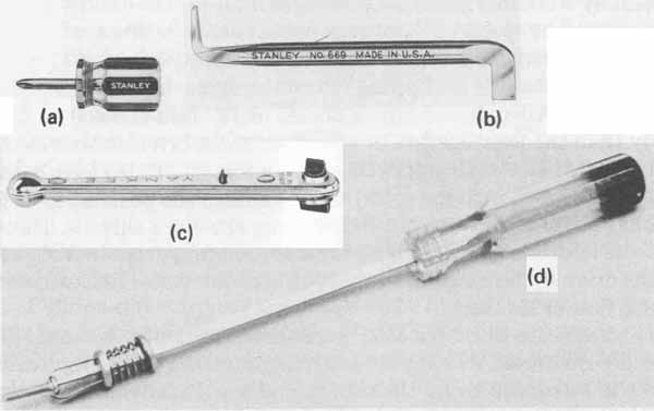
--- Fig.—11 Screwdrivers for special applications: (a) “stubby”; (b)
standard offset driver; (c) offset ratchet; (d) driver with screw-holding
mechanism.
The proper operating position of any screwdriver is always in alignment with the axis of the screw. This position minimizes the possibility of slippage damage and provides maximum surface contact area between the driver and the screw head.
Nutdrivers are used in a similar manner to screwdrivers but are designed to accommodate hexagonal-style machine nuts or screw heads. A set of nutdrivers is shown in FIG. 12a. They are available in sizes 6, 7, 8, 9, 10, 11, 12, 14, 16, and 18. The number represents the size in 32nds of an inch. For ex ample, a number 6 will fit a (i? hexagonal nut or screw head as measured across opposite flats. Sizes 6, 8, 10, 11, and 12 are most frequently used in electronics assembly. Sizes above inch are useful for the larger nuts associated with potentiometers and switches. The sizes of nutdrivers are often stamped into the shank or colored handles are provided for quick identification. A shank length of 4 inches is suitable for most applications. Nutdrivers are available with hollow shanks for threading nuts onto long machine screws that extend more than to inch into the driver.
A screwdriver in conjunction with a nut-driver should be used to assemble and disassemble hardware whose fasteners require considerable force. This technique is shown in Fig 23.12b.
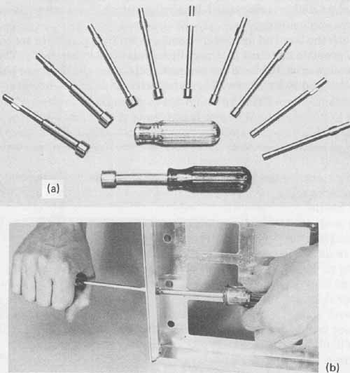
----FIG.—12 Hexagonal nut drivers: (a) nut-drivers are available with
individual handles or interchangeable handles; (b) combined use of nut-driver
and screwdriver.