AMAZON multi-meters discounts AMAZON oscilloscope discounts
cont. from part 1
5. WIRE CONNECTIONS
One of the most common types of terminal used to make interconnections between pc boards and chassis-mounted components is the swaged turret terminal discussed in Section 14. To obtain a good electrical connection, it is vitally important that a solid mechanical connection first be made. The wire to be soldered to a turret-type terminal should be formed as tightly as possible around the turret without scraping or nicking the conductor surface or deforming the wire contour. With the insulation positioned no more than inch away from the terminal, the conductor is first tightly formed 180 degrees around the turret with long-nose pliers (FIG. 9a). The excess length of wire is then cut at point A, which leaves a sufficient length to continue forming a complete 360-degree wrap-around connection. This wrap being formed with long-nose pliers is shown in FIG. 9b. Although 180-degree wraps are often used in electronic wiring, the 360-degree wrap provides the most secure mechanical connection. Long- nose pliers with smooth jaws should be used when making mechanical connections to any terminal configuration to avoid nicking and deforming the conductor surface.
Soldering to a turret terminal is performed using the soldering techniques discussed in Section 15 for soldering leads to pc board terminal pads. A small amount of solder is first applied to the soldering iron tip (solder bridge). The tip is next brought into contact with the wire and shoulder of the terminal, as shown in FIG. 9c. Positioning the tip directly opposite from the insulation will minimize heat damage to plastic and rubber insulation. Solder is applied immediately when the connection has reached the proper temperature (i.e., when the solder of the bridge or the solder used in tinning stranded wire begins to flow). Only a small amount of solder is necessary to make a sound electrical connection. If properly soldered, the contour of both the wire and the terminal will be plainly visible. A properly wired and soldered turret terminal connection is shown in FIG. 9d.
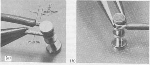
--- FIG.—9 Wiring to a turret-type terminal: (a) initial 180° wrap;
(b) forming the complete 360° wrap. (c) correct iron
tip and solder position; (d) properly soldered terminal.
During the soldering operation, the anti-wicking tool, shown in FIG. 7, or a lead heat sink, shown in Sec. 14 -- Fig.20, may be used to prevent wicking or excessive melting or burning of the insulation.
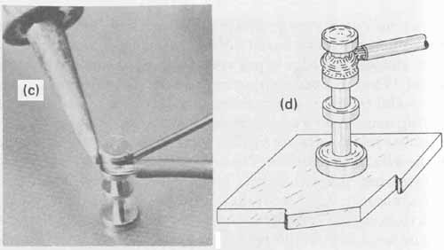
Wrap-around connections also find wide application when wiring to any eyelet-type terminal, such as those associated with terminal strips, switches, potentiometers, and pc board connectors. These terminal types are shown in FIG. 10a. Wire forming about an eyelet-type terminal lug begins by positioning the insulation no more than inch from the eyelet opening. The wire wrap is then formed in a similar manner to the 360-degree wrap for turret terminals, but since the cross section of the eyelet is a very thin rectangular shape, the wrap is more difficult to form. It is recommended that the first two 90-degree contours, as shown in FIG. 10b, be preformed before hooking the conductor through the eyelet. Once positioned into the eyelet, the excess lead length is cut at point A and the final 90-degree bend is made to complete the wrap (FIG. 10c). It is not good practice to make more than three wrap-around connections to a single eyelet nor to solder them until all have been mechanically formed.
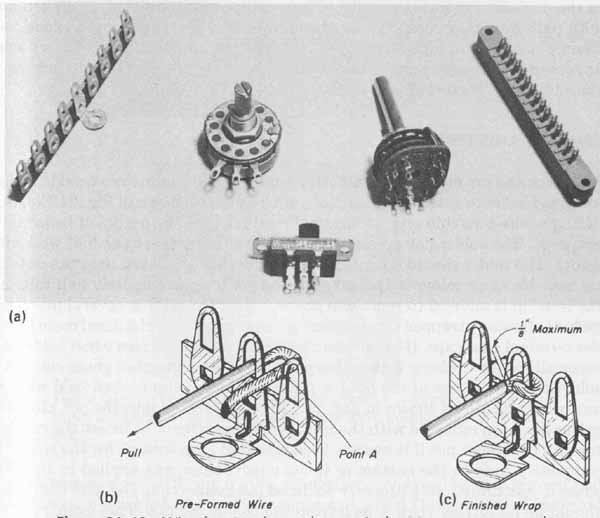
When mechanical strength requirements are minimal, wires can be soldered more easily into small-diameter holes, such as those found on solder lugs, by means of a feed-through connection, shown in FIG. 11. For this type of connection, the diameter of the wire should be approximately equal to that of the hole in the lug. As with other types of connections, the insulation is positioned at a maximum of inch from the terminal, with the prepared wire end passing through the lug hole. The excess wire is trimmed to within approximately inch from the terminal. Because the diameter of the wire approximates that of the hole, soldering will properly alloy both circumferences. The resulting connection is mechanically satisfactory and electrically sound, al though feed-through connections should be avoided in equipment that will be subjected to severe shock and vibration.
Wires may be dressed between connections by either point-to-point or square-corner wiring techniques. Point-to-point wiring, as the name implies, is a wiring technique used primarily in high-frequency circuits or any economical wiring application. Wiring interconnections are made with regard to the shortest routing path possible to minimize lead length, which is critical at high frequencies. This wiring technique is quicker and uses less wire than the other methods discussed here. Point-to-point wire dress usually does not add to the neatness of the package. However, with careful wiring positioning and neat soldering connections, the resulting wiring will be reliable and will display quality workmanship.
--- FIG.—10 Wire forming for eyelet terminals: (a) components and hardware
with eyelet-type terminals; (b) preformed wire; (c) finished wrap.
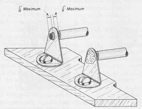
--- FIG.—11 Feed-through connection.
Square-corner wiring is a wire dress technique in which all wires installed in the package run either parallel or perpendicular to one another. When any wire path direction changes, the change is made with a 90-degree bend. Al though not used in high-frequency work, this technique imparts a very neat appearance to the package. The only disadvantage to square-corner wiring is the additional amount of wire and time necessary to complete a package.
6. SPECIAL WIRE ASSEMBLIES AND TECHNIQUES
Many connectors made for terminating the stranded conductors used in cables are provided with solder pot terminals, such as those shown in FIG. 12a. Soldering a wire into this type of terminal requires that the pot itself be initially prepared. The solder pot must be heated and filled at least one-half way with solder. The solder should not be allowed to flow out of the pot onto the outside surface. No more solder is applied after the pot is approximately half full, but the iron tip is allowed to remain in contact with the pot for several more seconds to allow any trapped flux or gases generated by the volatilized rosin inside the terminal to escape. (It is advisable to wear safety glasses when soldering, especially when working with solder pots, since the generated gases can cause solder to splatter out of the pot.) A properly tinned wire is then held with an anti-wicking tool, as shown in FIG. 12b, and inserted into the pot after the solder has been reheated with the iron. It will be difficult to insert the conductor into the solder pot if it has not been reheated long enough for the solder to completely melt to the bottom or if too much solder was applied to the wire when it was tinned. In a properly soldered pot connection, the wire insulation should be no further than inch from the top of the pot. This length can be predetermined on an unsoldered pot. There should be a minimum amount of solder used so that the contour of the wire strands between the insulation and the pot is plainly visible. In addition, no excess solder should be allowed to flow onto the outside surface of the pot. Excess solder puddling at the base of adjacent pots can cause short circuits. A properly formed solder pot connection is shown completed in FIG. 12b.
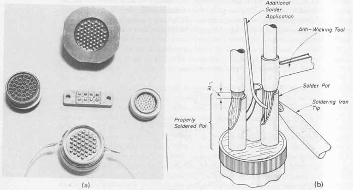
--- FIG.—12 Technique for wiring pot-type terminals: (a) typical pot-type
terminals; (b) soldering wire into pot-type terminal.
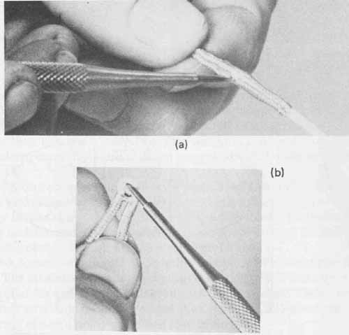
--- FIG.—13 Technique for preparing shielded wire for soldering: (a)
scribe used to provide access hole in shield; (b) removing signal lead
from shield.
A common yet difficult wiring connection involves the preparation and installation of shielded wire to phono plugs and jacks. The function of the braid of the wire is to cover and thereby isolate the inner (signal) conductor. There should be minimum exposure of the signal wire insulation after the shield and signal wire connections are made to the connectors. If the shielded wire has an outer insulating jacket, approximately 1 inches of the jacket should be removed. The shield is then pushed back from the end so as to “loosen it”. A pick (scriber) is then carefully worked into the braid without damaging any individual strands to form a hole large enough through which the insulated signal can be pulled. This technique is shown in FIG. 13a. The pick is then passed into the hole between the braid and the signal wire insulation so that it protrudes from the other side. Doubling the shielded wire back at the breakout point and lifting the pick will remove the signal wire from the hole in the braid. This technique is shown in FIG. 13b. The end of the braid is then tinned and will serve as the ground lead. The prepared shield and signal wire ready for soldering to a connector are shown in FIG. 14a. Soldering the signal wire to a plug requires preparation similar to that for solder pot terminals. The hollow center prong of the plug is first filled with solder. This step can best be done by gently gripping the outer shell of the plug in a bench vise. The correct soldering iron tip position and application of solder is shown in FIG. 14b. When solder begins to appear at the tip of the prong, the iron is removed. Solder must not be allowed to flow in the outer surface of the prong or it may prove to be impossible to plug it into a jack. To install the wires onto the plug, at least inch of signal wire is stripped and tinned, leaving only inch of insulation between the stripped signal conductor and the braid. The braid is also tinned. The center prong of the plug is reheated and the signal wire is inserted into the top of the plug until the braid is even with the top of the ferrule. Some of the signal conductor may protrude from the end of the prong. This is removed flush with diagonal cutters. The braid is next wrapped 360 degrees around the ferrule and then soldered, using the technique shown in FIG. 14c. Proper installation of shielded wire to a phono jack is shown in FIG. 14d.
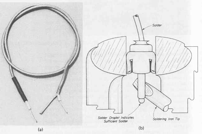
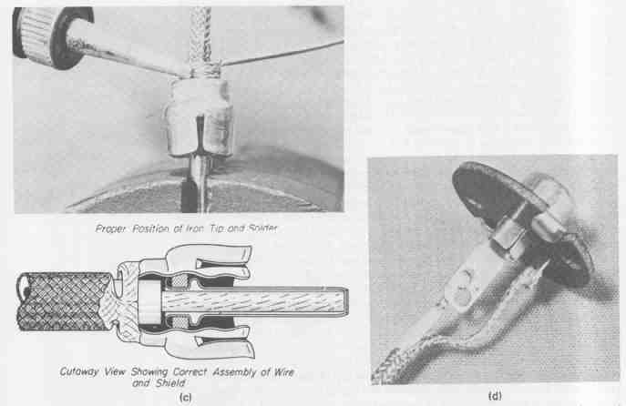
--- FIG.—14 Preparation and soldering of shielded wire to plugs and
jacks: (a) shielded wire prepared or soldering; (b) preparation of prong
with solder; (C) proper position of iron tip and solder; (d) correctly
prepared jack.
7 SOLDERLESS WIRING TECHNIQUES
Solderless- or crimp-type terminals provide a strong metal-to-metal (terminal- to-wire) bond that is suitable for applications using either stranded or solid wire. These terminals are particularly desirable in some production assemblies because they eliminate soldering. Two common configurations of solderless type (crimp) connectors are the ring tongue and fork tongue styles shown in FIG. 15.
Selecting the most suitable style depends on the application. If rapid connection and disconnection are not required but a higher degree of mechanical security is necessary, the ring tongue should be used. If, however, rapid connecting and disconnecting requirements are specified with no critical mechanical requirements, the fork tongue style is preferable.
The barrels of crimp terminals are available in uninsulated or insulated forms. The insulator is usually polyvinyl chloride (PVC) and offers a degree of strain relief for the wire if strong vibration is expected. These insulators are commonly available in colors so that the range of AWG sizes that each barrel will accept can be quickly identified (see TABLE 6).
Solderless terminals in common use in electronics have barrels that are capable of accepting wire sizes from AWG No. 10 to AWG No. 22. A No. 10 terminal will accept both AWG Nos. 10 and 12 wire; a No. 14 terminal will accept AWG Nos. 14 and 16 wire; and a No. 18 terminal will accept AWG Nos. 18, 20, and 22 wire. The terminals are available to accept screw sizes from No. 4 to inch.
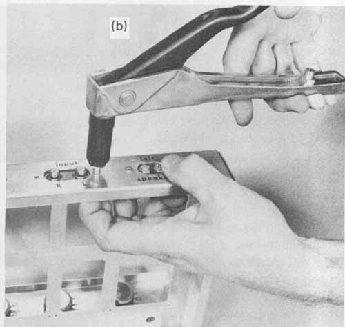
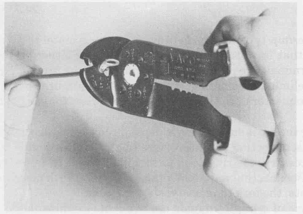
Conductors are assembled into solderless terminals with a crimping tool such as the one shown in FIG. 16. The wire insulation is stripped to a length equal to the metal barrel length. The conductor is then inserted into the terminal until the insulation seats against the end of the metal barrel. The barrel is then placed into the appropriate jaw crimping position of the tool. The split side of the barrel should be placed against the smooth portion of the jaw opposite the crimping tooth. When the handles are firmly squeezed together, as shown in FIG. 16, the barrel will be crimped against the conductor and will make a sound mechanical and electrical connection.
--- FIG.—15 Crimp terminals.
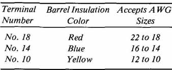
--- TABLE 6 Color Code for Insulated Crimp Connector Barrel Sizes
--- FIG.—16 Technique for installing crimp terminals.
8. WIRE-WRAP CONNECTIONS
An alternative method of providing randomly located metal studs to which external connections cam be made without the necessity of soldering wires is through the use of wire-wrapping techniques. Wire-wrap terminals are square or rectangular pins having at least two sharp corners that are mechanically se cured to the pc board by staking (press-fitted) or soldering. Lead connections are made to these pins with mechanical or pneumatic wire-wrapping tools using solid wire. The resulting connection is both mechanically secure and electrically sound.
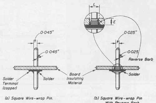
--- FIG.—17 Styles of wire-wrap terminals: (a) square wire-wrap pin;
(b) square wire-wrap pin with reverse barb.
Two types of wire-wrap pins are shown in FIG. 17, each having its own configuration and mounting arrangement. The most basic wire-wrap pin is shown in FIG. 17a. It consists simply of a 0.045-inch-square wire from to 2 inches long with both ends tapered for ease of initial insertion into the pc board. No special equipment is required for their installation since the pin is simply pressed into a predrilled hole. The recommended drill hole has a diameter of 0.050 inch with a 0.002-inch tolerance. Although commercially available vibrating tables and templates are employed to position the pins into the holes, the cost of such equipment is prohibitive in small volume or prototype work. These pins can be inserted easily by hand. The tapered end of the pin is first inserted into the drill hole of the board using finger pressure. This procedure is sufficient to temporarily hold the pin in a staking position. Similar to the staking of solder-type terminals, an arbor press is used with an anvil and flat-faced setting tool (see Sec. 14). The guide hole in the anvil should be large enough to accept the square configuration of the pin with sufficient clearance. The arbor press then is used to force the pin through the pc board, allowing it to extend to any desired height on the opposite side of the board. Although only held in position by the contact between the corners of the pin and the inside edge of the hole, it is sufficiently gripped in place until it can be soldered to the terminal pad. Connecting wires are then wrapped along the length of the pin extending above either side of the board.
Another wire-wrap terminal that provides for uniform staking height is shown in FIG. 17b. It consists of double-ended square stock with either 0.025-inch or 0.045-inch flats made of brass and plated with gold alloy. Dimension E in FIG. 17b is generally selected to be equal to the thickness of the pc board insulating material. To insert this pin, a hole is drilled that is approximately 0.002-inch smaller than the maximum diameter of the reverse barb. For the 0.025-inch square pin, dimension L is 0.052 inch (hole size 0.050 inch) and for the 0.045-inch square pin it is 0.096 inch (hole size 0.094 inch). The pin is positioned in such a manner as to allow its crown to contact the foil side (terminal pad) of the board. The pin is then secured with an anvil and setting tool in an arbor press. The reverse barb prevents the pin from turning or backing out of the insulating material. Soldering between the crown and terminal pad will make a reliable electrical connection.
Mechanical and electrical connection for wire-wrap terminals is achieved by wrapping, under tension, solid wire around a post terminal that has at least two sharp edges. These edges, as well as the wire itself, are deformed when tightly wrapped. The average pressure between the wire and the sharp contact points of the post is in the order of 30,000 psi, which is more than sufficient to produce a sound mechanical and electrical connection. Two properly formed types of wire-wrap connections are shown in FIG. 18.
Wire-wrap connections are formed by manual operation and automatic or semiautomatic wire-wrapping machines. Manually operated wire-wrap tools, such as the one shown in FIG. 19a, are available to quickly form wire-wrap connections. Pneumatic wire-wrap tools are also available, but are usually employed with semiautomatic machines in mass-production applications.
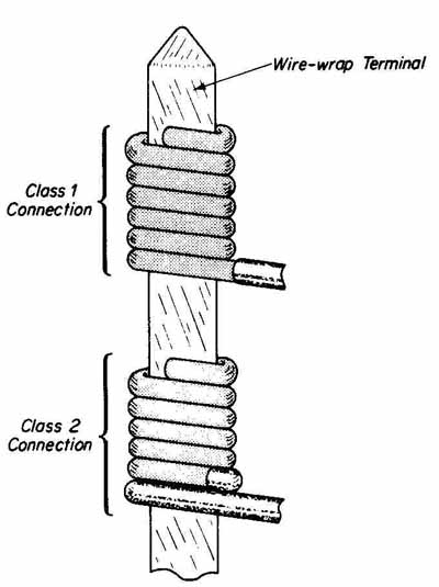
--- FIG.—18 Two styles of wire wrapping.
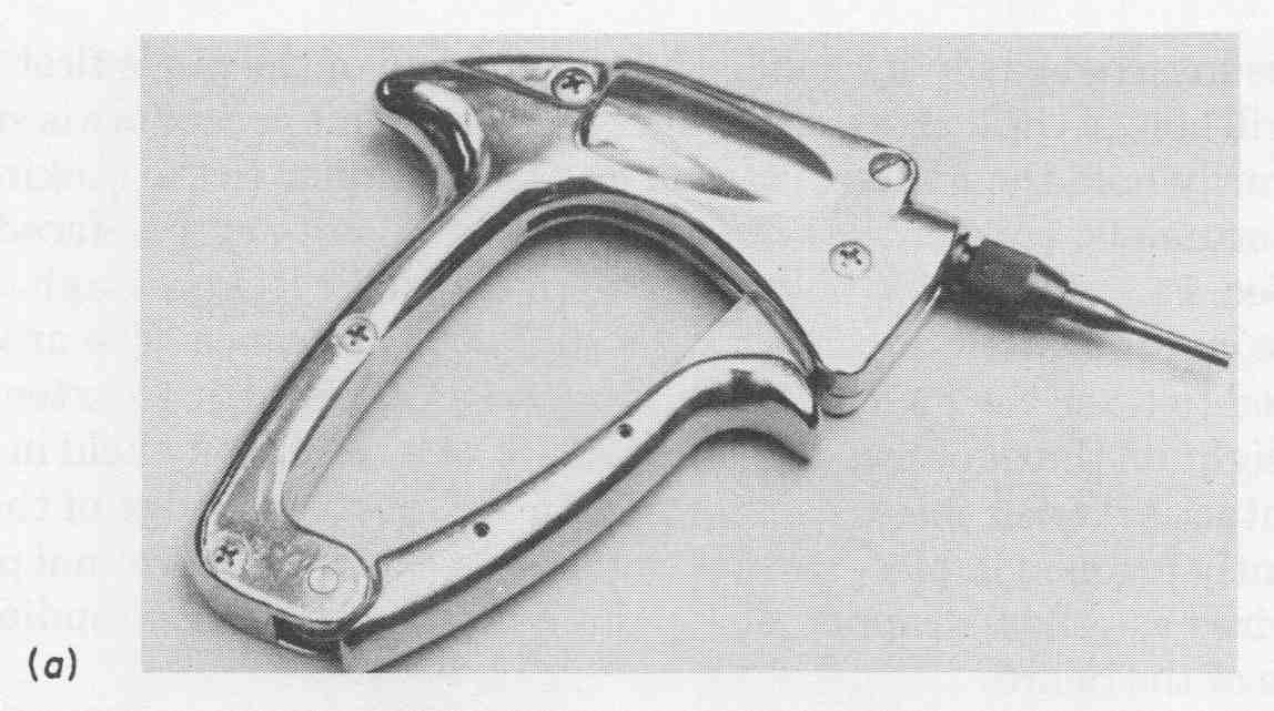
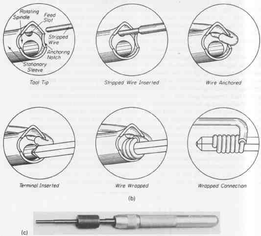
--- FIG.—19 Hand operated wire-wrapping tools and wrapping method: (a)
hand operated wire-wrap tool; (b) wire-wrap connection process; (c) de-wrapping
tool.
To use the tool shown in FIG. 1 9a, solid wire of the desired gauge is first stripped and then inserted into the outermost hole at the end of the wire wrap ping tip. (FIG. 19b). The tip is then positioned over the terminal and the trigger is quickly squeezed. The nose of the gun spins the wire around the terminal to form the desired connection.
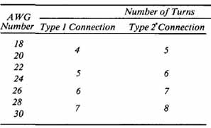
--- TABLE 7 Recommended Wiring Specifications for 0.025 and 0.045-Inch
Square Wire-Wrap Terminals
*Type 2 indicates one turn of insulated conductor contacting the terminal. ---
The number of turns of wire wrapped is determined by the specifications provided in TABLE 7. The amount of insulation that must be stripped from the end of the wire can be quickly determined by trial and error.
Should it be necessary to unwrap a connection that is not readily accessible (on high-density packaging, wrapped terminals maybe within 0.1 inch away from each other) de-wrapping tools such as the one shown in FIG. 19c are available. To remove a wrapped connection, the center hole in the nose is positioned over the terminal. Downward pressure of the tool against the wire will quickly unwrap the wire from the post. The tool must be kept vertical during the entire operation to avoid bending the terminal post.
When the number of terminal connections to be made becomes impossible to manually wire wrap at a cost-effective rate and without excessive errors, semiautomatic and fully automatic wire-wrapping machines are employed. One application of dense wiring includes that of large backplanes having thousands of wiring terminals on one side and heavily populated on the other side with printed circuit board or cable connectors. Another example is on panels requiring the discrete wiring of vast numbers of integrated circuit sockets.
Semiautomatic wire wrapping is performed on a machine having a vertical worktable to which the panel to be wired is clamped. Data-controlled carriages move the table in both x and y directions. The table movement is such that each new pin to be wired positions itself in front of the operator. This feature aids in reducing operator fatigue. A terminal pointer with a tool guide (mounted wrap ping tool) traverses the x axis and stops after each table repositioning in front of the next terminal to be wrapped. The operator feeds the specified size of wire into the tool guide and, with slight pressure, pushes the tool onto the pin to make each connection. Rates of between 450 and 600 wraps per hour are typical with semiautomatic machines.
When higher wiring densities and speeds exceed the capabilities of semi automatic systems, a fully automatic wire-wrapping machine, such as that shown in FIG. 20a, is employed. This machine has an operator’s console which includes the following: manual operating switches and data input, fault monitoring system, cycle counter, cycle interrupt, emergency stop, repeat wire operation, and sequence number readout.
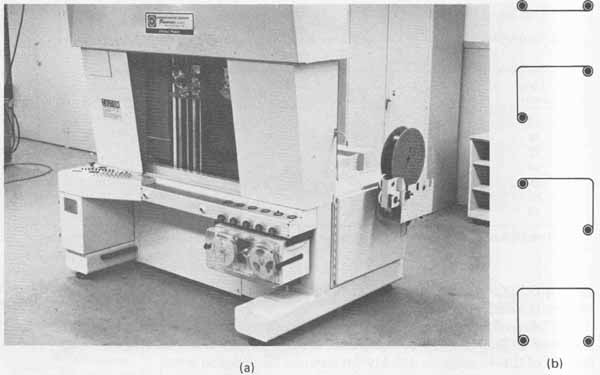
---FIG.—20 (a) 14EV vertical wire-wrapping machine, courtesy of EPE
Technology; (b) basic wire patterns.
The panel to be wired is clamped vertically inside the machine. Unlike the semiautomatic machines in which the board moves only in the x and y directions, the automated systems also provide for 90-degree board rotation. Two sets of programmable wire-wrapping tools and dressing fingers are mounted on two vertical carriages which are also data controlled. The dressing fingers form the specified contour of the wire as it is routed above selected channels between closely spaced terminal locations. After the wire-pattern excursion is completed between the two terminals, the machine automatically strips and cuts the wire to length. The tool bits then lower the wire ends over the two terminals to be connected and simultaneously form the wire wraps. One wrapping bit rotates clockwise while the other end of the wire is wrapped in a counterclockwise direction. The basic wire patterns formed are shown in FIG. 20b. The symbols at the bend locations represent the use of a dressing finger to form the pattern. The data also includes the z levels to obtain the specified height of the wire wrap on the terminal. This ensures proper spacing between multiple wraps on a single terminal. Because wire wrapped in opposite directions may result on the same terminal, the spacing between these wraps is critical to prevent a wire being installed from disturbing one previously formed.
The automatic wire-wrapping machine shown in FIG. 20a will accommodate a panel size of up to 26 by 26 inches with a wrap area of 22 by 22 inches. It is made to wrap AWG Nos. 26 and 30 wire at a rate as high as 1100 to 1200 wraps per hour.
Several terminals properly wrapped with solid wire are shown in FIG. 21. The type of wire normally used is copper-alloy solid wire with a tin, silver, or gold plating. Sizes of wire for this application range from AWG (American Wire Gauge) No. 18 to No. 26. The size of the wire will determine the exact number of turns to make a properly wrapped connection. This information for two types of interconnections is given in TABLE 7. The type 1 interconnection requires that the wire be wrapped around the terminal with its insulation approximately inch from the first turn; type 2 interconnections require that at least one turn of insulation also be formed around the terminal. This second classification utilizes the flexibility of the wire insulation to reduce stress en countered during vibrations of the wire at the point where it enters into the first wrap on the terminal. In addition, quality workmanship dictates that no more than three independent lead wraps be made on a single terminal pin and that (1) turns from one independent wrap do not overlap any portion of another wrap, (2) adjacent turns on the same wrap touch but do not overlap, (3) the sum of all gaps should not exceed one wire diameter excluding the first and last turns, (spiral and open wrap), (4) there are not insufficient turns, and (5) the wire end does not protrude from the terminal (end tail). The appearance of unacceptable wire wraps is shown in Fig. .22a.
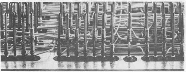
--- FIG.—21 Wire-wrap assembly. Courtesy of Augat, Inc.
It is often the case that several terminals must be connected together or bussed. To avoid later servicing problems, bussed pairs of terminals to be connected should be provided with level 1 wraps first, followed by level 2 wraps to complete the string. Alternately wrapping terminals from level 2 to level 1 is unacceptable. If a wire that has its end wrapped at different levels must be relocated, the entire string may have to be removed to replace only one wire (see FIG. 22b).
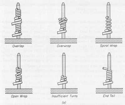
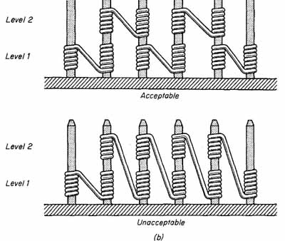
--- FIG.—22 Wire wraps and bussing technique: (a) unacceptable wire
wraps; (b) bussing.
Proper locations of both wire wraps and routing is essential to optimum circuit performance, especially in high-speed circuitry. If a signal wire in this type of design must be relocated because of stray inductance or capacitance problems, it is important that proper wire-wrap levels are adhered to through out the design. Also, to reduce the number of parallel wires, advantage of the machine’s data-controlled pallet-rotation ability should be taken. The software can be used to spread out the wires and result in a marked reduction of density buildup, in addition to a reduction in the number of parallel wires.
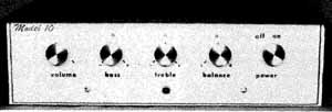
---FIG.—23 Completed stereo amplifier.
With the wiring completed, the finished amplifier system is shown in FIG. 23.
EXERCISES
A. Questions
1 What is the reason that copper wire is tin-coated?
2 What is the advantage of stranded wire over solid wire?
3 Define the term bus wire.
4 Why is concentric-type wire preferred over bunch-type wire?
5 What does the abbreviation AWG represent?
6 Explain the terms mil-foot and circular mil.
7 Determine the resistance of 3 feet of AWG No. 22 copper wire.
8 What is the relationship between cross-sectional area and AWG number of copper wire?
9 What is the relationship between current-carrying capacity and AWG number?
10 What three criteria determine the most suitable wire insulation for a specific application?
11 Place the following insulation materials in order of poor, fair, good, and excellent for insulation resistance: Teflon (TFE), nylon, Mylar, and Kyrar.
12 Describe the body and tracer colors of hook-up wire in a harness assembly that is assigned the code number 528.
13 What is Government Standard MIL-STD-122?
14 What is the primary difference between coaxial cable and shielded wire?
15 What is meant by the term wicking, and how is it prevented?
16 How is standard wire prepared prior to making a connection to a terminal?
17 How are solder pot terminals prepared before soldering the wires?
18 What is the number and barrel color of a crimp terminal that will accept AWG wire numbers 22 to 18?
B. True or False
Circle T if the statement is true, or F if any part of the statement is false.
1 Unidirectional stranded wire is more flexible than the counter-directional type, but its diameter is not as precisely uniform. T F
2 In the AWG system, as the numbers increase, the corresponding wire diameters decrease. T F
3 Wire resistance increases by a factor of 4 when the diameter is doubled. T F
4 The term circular mil refers to the diameter of wire. T F
5 When measuring the size of stranded wire with a wire gauge, the slot that it snugly fits into will be one AWG number more than the gauge reading due to the space between strands. T F
6 Shielded wire is made to be used on low-frequency applications where its impedance is not critical. T F
7 When tinning stranded wire with a soldering iron, the wire is positioned between the solder and the iron’s tip. T F
8 When forming wrap-around connections, the wire insulation should touch the terminal to prevent the possibility of shorts between adjacent terminals. T F
9 The maximum insulation gap for pot-type terminals is 1/16 inch T F
10 A crimp connector having a red barrel will accept a larger- diameter wire than will a connector with a yellow barrel.
C. Multiple Choice
Circle the correct answer to each statement.
1 Wire having an AWG number of 22 is (smaller, larger) in diameter than one having an AWG number of 16.
2 AWG No. 22 wire has a (smaller, larger) current-carrying capacity than AWG No. 14 wire.
3 The most common material used for coating copper wire is (tin, nickel).
4 The AWG wire numbering system was developed primarily to designate the size of (stranded solid) wire.
5 (Solid stranded) wire is used to make electrical connections to wire-wrap terminals.
D. Matching columns
Match each item in column A to the most appropriate item in column B.
COLUMN | A COLUMN B
1. Diagonal cutters 2. AWG 3. Wire-wrap 4. Stranded wire 5. Kel-F 6. Coaxial cable 7. CM |
a. Insulation b. Cross-sectional area c. Full-flush d. RF circuitry e. American Wire Gauge f. Solderless g. Concentric |
E. Problems
1 Construct a pair of test leads such as those shown in FIG. 24. The test leads are to be made from 36-inch lengths of plastic insulated No. 18 AWG stranded wire. Strip inch of insulation from all four lead ends and twist and tin the stranded conductors. Slip the rubber insulated grips onto the leads before soldering the alligator clips to the lead ends. After soldering the clips, slide the rubber insulators into position.
2 Construct a set of interconnecting leads for a stereo system by first centering a 2-foot length of shrinkable tubing about two 3-foot lengths of insulated shielded conductor cables. Slide 2-inch lengths of shrinkable tubing over all four ends of the cables. Remove sufficient outer insulation from all cable ends to prepare the copper braid and the inner insulated conductors for soldered connections to RCA phono plugs. Once the phono plugs have been soldered, slip the shrinkable tubing onto the plugs until the end of the tubing is even with the leading edges of the outer portion of the connector. Finally, shrink the tubing about the cables and plugs.
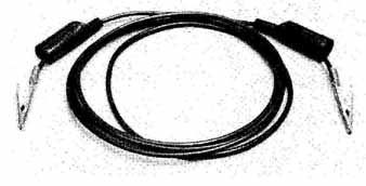
--- FIG.—24
3 Construct four 6-foot speaker leads from plastic insulated No. 16 AWG stranded wire. Slide 1 inch lengths of shrinkable tubing over all lead ends. Strip and tin all lead ends to a length of inch. Position the uninsulated barrels of solderless fork tongue connectors onto all prepared conductor ends and crimp. Slide the shrinkable tubing over the entire barrel length and shrink into place.
4 Using the technique discussed in this section for straightening bus wire, prepare a 32k-inch length of tinned No. 14 AWG bus wire to construct a UHF antenna. Form the wire into a loop with a 7 diameter. Ad just the loop so that both loop ends overlap equally. Crimp solderless spade lugs onto both loop ends and form two 90-degree bends on each end for attachment to terminal lugs on the rear of a television set. The first 90-degree bends are to be made 4 inches from the end of the spade lugs and perpendicular to the circumference of the loop. The remaining 90-degree bend is to be located 2 inches from the ends of the lugs for the most convenient attachment.
5 Install plastic insulated No. 20 AWG stranded wire between the chassis- mounted components and hardware and the pc board for the seven fixed- interval UJT timer designed, fabricated, and assembled in Problems 11.3, 13.4, 14.3, 15.3, and 23.5.
6 Install interconnection wires to the tachometer designed, fabricated, and assembled in Problems 11.5, 13.3, 14.5, 15.5, and 23.6. All leads will be plastic insulated No. 18 AWG stranded wire. The power lead insulation color is to be red, with lead length sufficient for connection to the battery side of the fuse block. The ground lead insulation color should be black. This lead is to be terminated with a solderless spade lug and attached to any convenient screw on the car chassis. Select green for the insulation color for the remaining lead to be connected to the distributor side of the coil. A solderless ring tongue connector of sufficient size for the coil connection should be crimped onto the end of the green lead.