AMAZON multi-meters discounts AMAZON oscilloscope discounts
LEARNING OBJECTIVES:
.Upon studying this section on harness and cable fabrication, the student should be able to:
1. Recognize which circuits are suitable for harnessing.
2. Know the terms used to describe the various parts of a harness.
3. Prepare harness assembly drawings.
4. Prepare wiring tables to accompany the assembly drawings.
5. Develop a harness jig.
6. Properly fabricate and lace a harness.
7. Use cable ties to fabricate a harness.
8. Use heat-shrinkable tubing for harness fabrication.
9. Fabricate cables with the use of solid-wall or split-wall tubing.
10. Test cables for shorts or opens.
0. INTRODUCTION
Wire harnessing and cabling are alternate interconnection methods and extensions of the wiring procedures considered in Section 24. Whenever two or more wires are mechanically secured or bundled together, a harness or cable is formed. The distinction between these two terms depends on the application. Harnesses are defined as wires mechanically bundled together to complete the electrical interconnections within a chassis assembly. They are characterized by leads leaving the main trunk and routed to components, terminals, or sub-assemblies such as pc boards. A cable is a bundle of individual wires each starting at one end of the bundle and terminating at the opposite end. The bundle is generally formed by passing wires through a protective insulated tubing. The assembly is completed by soldering connectors at both ends to provide for electrical interfaces. The ends of the cable may also be terminated with the individual leads stripped and tinned for soldering to terminal points. Cables are employed for external interconnections among separate units in a system.
This section provides information for the design and construction of harnesses and cables, including harness assembly drawings, termination and wire-coding techniques, harness jigs, lacing, cable ties, and cabling tools. Also considered are shrinkable and track closure tubing and various types of cable clamps for securing harnesses and cables.
1. CONSIDERATIONS FOR HARNESS DESIGN
The decision to construct a harness will depend on the mechanical and electrical requirements of the circuit. Although ribbon and flat printed circuit cable, such as those shown in FIG. 1, have in many instances replaced individual wiring, twisted pairs, coaxial cable, and standard round-wire harnesses, conventional cable and harnesses continue to be widely used because lead ends require no special connectors for termination and standard soldering techniques are employed.
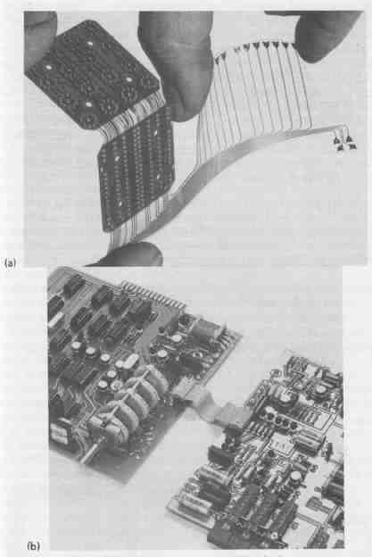
--- FIG.—1 Ribbon and flat printed circuit cables facilitate interconnections:
(a) flat cable, courtesy of Fortin Laminating Corp.; (b) ribbon, courtesy
of 3M Company.
Since harnessing is employed in prototype construction in anticipation of production, it must be considered as a means of interconnection. Not all circuits are suitable for harnessing, however. Circuits with few peripheral connections within a chassis are not usually harnessed and may best be wired by the routing techniques discussed in Section 24. Circuits with many interconnections may be harnessed if the electrical considerations will allow. For example, high-frequency circuits demand that lead lengths be as short as possible. This requirement necessitates point-to-point wiring and a harness should not be employed. In high-gain, low-frequency circuits, harnessing is not recommended, since interstage coupling between parallel conductors may cause signal interference, especially at the low-signal-level inputs. For most other types of circuits whose wiring serves such functions as dc power and ground leads, high-level signal leads, low-level signal leads employing shielded or coaxial cable, ac power leads (when formed into twisted pairs), as well as bypass and coupling leads, may be considered for harnessing. Harnesses are also used extensively when shock and vibration problems exist.
Harnessing lends itself readily to mass-production applications because the harness can be formed apart from the assembly for which it is intended by any of the methods discussed in Sec. 3. When the harness is properly bundled and formed, it is positioned into the chassis and interconnections are made among the various chassis-mounted components.
2. HARNESS ASSEMBLY DRAWINGS
To permit a better understanding of harness design and construction, some common terms used to identify the various parts of a harness, shown in FIG. 2, will first be defined.

--- FIG.—2 Harness nomenclature.
Breakout: two or more unlaced leads leaving any portion of a harness assembly at the same breakout point
Breakout point: space between lacing or cable ties where a lead or group of leads leave any portion of a harness
Fanout: individual leads leaving a leg at regular spaced intervals
Harness contour: overall shape of the harness assembly
Lacing: method of bundling individual leads to form a harness using waxed lacing cord or twine or nylon lacing tape
Lead: individual insulated conductor
Leg: minor run of two or more laced leads
Trunk: major run of the harness assembly containing the largest number of laced leads
Wire run: complete route of an individual lead in a harness assembly
Harness design begins with a detailed harness assembly drawing such as that in FIG. 3 for the amplifier. This drawing will be used to construct both the harness jig and the actual harness. For this reason, it must be detailed to provide sufficient information for the harness contour, including all wire runs and configurations of leads, legs, breakouts, and fanouts. In addition, the type and number of terminations on each breakout or leg as well as a descriptive designation for each major termination on the harness should be provided.
The harness assembly drawing is produced from the chassis and component layout drawings in conjunction with the schematic diagram. The exact harness dimensions and contour are determined from the chassis and component layout drawings, whereas routing paths and originating and terminating points are obtained from these drawings and the schematic diagram. To be useful, the harness assembly drawing should be constructed using a 1 1 scale. The dimensional and positional information can be most accurately shown if constructed on a grid system having 10 divisions per inch. For clarity, all harness segments (trunks and legs), regardless of how many individual leads they may contain, are indicated by single solid lines that form the harness contour. (Note that the harness assembly drawing is a bottom view of the harness, which rests against the chassis.) In addition, each lead of a fanout or breakout is also represented by an individual single line. Dimensioning of the drawing should be done in a random fashion for simplification if a one-to-one scale and grid system are not used.
The trunk of the harness shown in FIG. 3 is so indicated. Identifying the trunk allows rapid determination of the most complex portion of the harness to be constructed, since it contains the largest number of leads.
Since a harness may contain many leads for terminations, each should be literally described concerning its function to simplify initial harness fabrication and final installation. This information is tabulated in a Wiring Table such as the one shown in TABLE 1 for the harness of FIG. 3. As seen in this table, the letters PS are used to designate the terminations of the wire runs connecting the power supply pc board. Minor classifications within the major designations should also be descriptive. Within the major designation of PS, VCC-L is used to indicate the lead connection for the dc voltage of the left channel and PA-12 designates the dc voltage for the preamplifier pc board.
The wiring table used in conjunction with the assembly drawing provides sufficient information to accurately construct a harness. Each entry in the wiring table represents an individual lead in the harness. Each wire run is listed separately with its complete descriptive information relative to its To and From locations, lacing termination distances, type of lead termination at each location, color of lead insulation, AWG number, type of insulation, type of wire, and length of each run.
An explanation of the first entry in TABLE 1 will serve to show the complete description of a wire run. A 19-inch lead made of No. 20 AWG solid copper wire with red plastic insulation having a white stripe (tracer) will connect to the (PS-VCC-L) power supply pc board at the left channel dc voltage terminal where the insulation is stripped inch from the end. Lacing will terminate inch from this end. The other end of this lead will terminate at the (P-VCC-L) left channel dc voltage terminal of the power amplifier pc board where the insulation is stripped from the end. Lacing will terminate 9 inches from this end.
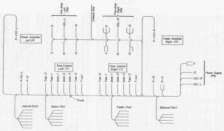
--- FIG.—3 Assembly drawing for the amplifier harness.
--- FIG.—4 Functional wiring layout for the amplifier circuit.
The wiring table may be modified for purposes of simplicity when applicable. For example, in low-volume production work, it may be economically advantageous to individually cut to size and strip each lead as it is placed into the harness, thus eliminating the need for the lead length column. Where all stranded or all solid wire with the same type of insulation is to be used, these two designations are also unnecessary. Finally, it may be desirable from the standpoint of uniformity to select a common wire size for the entire harness that meets all electrical requirements of the circuit. This would further simplify the wiring table. In any event, the wiring table should contain the following minimum information. To-From locations, lacing termination distances, type of terminations, and insulation color code.
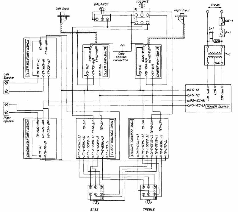
The harness assembly drawing and the wiring table are developed only for the fabrication of a harness. Once the harness has been installed into the system, there is no further use for these aids. Circuits with large complex harnesses should be provided with a functional wiring layout to aid the service technician in testing or troubleshooting. This type of layout for the amplifier circuit is shown in FIG. 4. Functional wiring layouts are best developed on a grid system having four divisions per inch. Major chassis-mounted components are represented along the edges of the paper. Examples of these components are pc boards, transformers, lamps, fuses, meters, switches, and potentiometers. These components are randomly oriented and in such a location as to simplify the wiring layout. No attempt should be made to position them in accordance with their location on the actual chassis. With all components randomly positioned on the drawing, their terminals are identified using the same coding system used on the wiring table. Wire runs are then drawn using the grid lines as guides for spacing. These wire runs are drawn horizontally and vertically with routing only at right angles between To and From positions established from the schematic diagram. The object of this type of drawing is to present a clear, easily read wire trace of the package. For this reason, closely spaced lines representing wire runs must be avoided. In addition, all wire runs should be clearly identified in terms of color code (obtained from the wiring table) for rapid identification in servicing.
3. HARNESS JIG
The simplest method of developing a jig for the construction of a harness is through the use of a plywood panel and wire brads. A grid system having 10 divisions to the inch is first taped securely to the plywood panel. From the harness assembly drawing, the harness contour is accurately reproduced on the grid system. An alternative method is simply to tape a copy of the original harness assembly drawing onto the panel. All lead terminations and identifications are accurately positioned. With the harness contour completed, 1-inch brads (serving as jig pins) are driven into the board to help position the wire runs exactly over the harness contour lines. Brads are positioned on both sides of the contour lines at a spacing that will accept the diameter of that portion of the harness that will be developed as the various wire runs are passed between them. Additional brads are used at each breakout point to guide the leads of various breakouts or legs into the correct position. Breakout points for individual leads or fanouts along the harness will require more closely spaced brads since they will accommodate only a single lead diameter between them. How ever, these brads should not be spaced so close as to interfere with the lacing process. Finally, brads are positioned beyond the lead termination point at each end of all wire runs to tie off each lead end. Each lead is tied off as it is placed into the jig to hold it into position and to maintain all leads taut as the harness is being formed. The brads inserted for this purpose are positioned be yond the termination points of the harness so that wire distortion caused in tying off leads ends will be removed when leads are cut to size as indicated on the harness assembly drawing. The lead length specified in TABLE 1 includes an additional length for tie-off purposes over and above the actual termination length necessary for the completed harness. An arbitrary additional length of approximately 3 inches per end is usually sufficient to tie off a wire run.
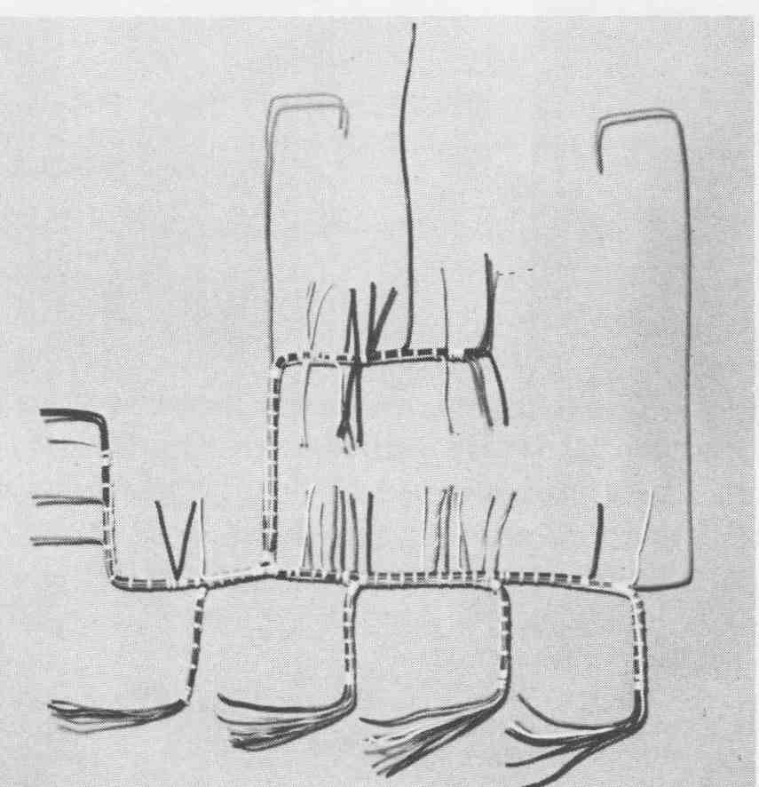
With all brads positioned, the individual wire runs are checked off from the wiring table as each is placed into the harness jig. When positioning the wire runs that will form a breakout from the trunk, it is important to orient these leads closest to the brads on the side of the harness from which the break out will occur. This will minimize crossovers that tend to distort the harness contour. Continual checking of wire run positions during this phase of construction is absolutely essential to ensure optimum routing as well as to verify that all required wire runs are included before the leads are bundled. Once a harness has been completely laced, it is a very difficult and time-consuming task to add a wire run or to change the routing of a lead. A harness jig with the harness partially formed is shown in FIG. 5.
The major concern in harness construction is to produce a harness that will exactly duplicate the contour and dimensions on the harness drawing so that it will properly fit into the finished package.
When all the leads have been correctly placed in the harness jig, the bundling of the harness may begin. All lacing of the harness must be performed in place. If any section is lifted out from between the brads during lacing, dimensioning accuracy between breakout points may be lost. The two common methods of bundling a harness are lacing and employing cable ties. Both methods result in a rigid and secure harness.
4. LACING
Lacing involves the formation of a series of evenly spaced locking hitches or “knots” along the trunk and legs. This form of bundling requires the use of lacing cord twine, or tape. Many types of lacing material are commercially available, such as waxed linen, polyester, nylon, and Teflon. Each of these is available with their fibers impregnated with substances such as wax, silicone, or vinyl resin to better grip the lock hitches. Flat-lacing tapes are better than round cord or twine, since they provide a larger contact surface around the leads of the harness and are less likely to cut into the wire insulation when pulled tight. All these lacing materials have a minimum breaking force in pounds, varying with the material and the size. A typical -inch-wide tape has a minimum breaking force of approximately 25 pounds, although lacing materials are available with breaking forces as high as 200 and as low as 10 pounds.
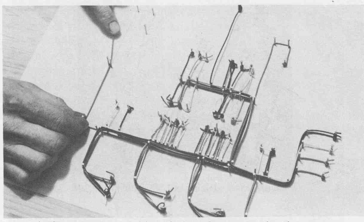
--- FIG.—5 Amplifier’s harness being completed on jig.
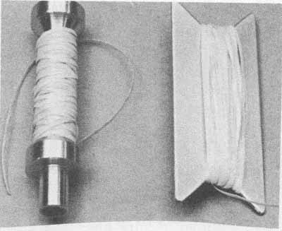
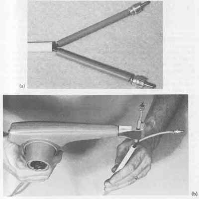
--- FIG.—6 Lacing bobbin and shuttle.
Initial lacing of the harness begins at one end of the trunk. To aid in lacing, a bobbin or shuttle, as shown in FIG. 6, may be used. A sufficient length of lacing tape is wound on one of these lacing aids to complete the lacing of the entire trunk of the harness. This length should approximate four to five times that of the section to be laced to avoid splicing. Splicing of lacing materials is highly undesirable since a potential break is formed if the splice is weak and the splice makes an unsightly knot. The bobbin or shuttle is also used to help pull the lacing tape to tighten the locking hitches. If a great deal of lacing is to be performed, a lacing glove, shown in FIG. 7, should be worn to protect the hand and fingers from the abrasive action of the tape.
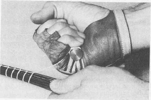
--- FIG.—7 Lacing gloves are used for protection.
The girth hitch is often used to initiate the lacing process. The sequential procedure for forming a girth hitch is shown in FIG. 8. In FIG. 8a, one end of the lacing tape is wrapped into a double loop. The free end of the tape and the bobbin are then passed through this loop (FIG. 8b). Tension is simultaneously applied to the free end of the tape and the bobbin to dress the girth hitch firmly against the leads. Completion of the girth hitch is shown in FIG. 8c. The trailing end of the lacing tape is then laid flat between two adjacent leads and a series of four tightly grouped locking hitches are formed against the girth hitch as well as over the free end of the tape to prevent the girth hitch from slipping out of position. This completes the originating point of the harness, which is shown in FIG. 9a. One of several types of these locking hitches is shown in FIG. 9b. After the initial four locking hitches are formed against the girth hitch, the running hitches may be begun. These are formed in the same way as locking hitches. The term locking hitch refers only to tightly grouped hitches whose function is to “lock” the girth hitch and breakout point positions. When this type of hitch is used solely to bundle the remaining portions of a harness, it is referred to as a running hitch.
The type of hitch shown in FIG. 9 is preferable since it provides excel lent security at each individual tie point. The running hitches should be uniformly spaced at a distance approximately equal to the diameter of the harness at any point but never less than inch apart (FIG. 9c). The selected spacing distance should be consistent throughout the entire harness. Each hitch should be pulled firmly to ensure positive gripping but should not be so tight as to damage the insulation of the individual leads within the harness.
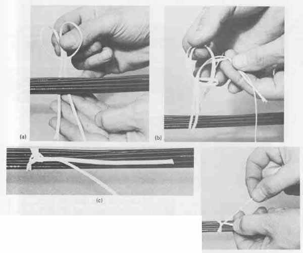
--- FIG.—8 Sequential procedure for forming a girth hitch: (a) forming
double loop; (b) both lacing ends are passed through double loop; (c)
partially tightened girth hitch.
--- FIG.—9 Forming lock and running hitches: (a) originating point of
harness; (b) formation of a running hitch; (c) evenly spaced running
hitches.
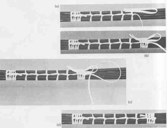
--- FIG.—10 Terminating technique for lacing: (a) loop used for termination;
(b) terminating lock hitches; (C) end of lacing tape feed-through loop;
(d) completed termination.
When the lacing termination point on a trunk or leg of the harness is reached, as specified on the wiring table, a special technique for termination is used, shown in FIG. 10. After the last running hitch is formed, a small loop of the tape is placed flat against the harness extending toward the termination point (FIG. 10a). Four tightly grouped locking hitches are then formed over the loop. This procedure is shown in FIG. 10b. To complete the termination, a sufficient length of tape is cut from the bobbin and inserted through the ex posed end of the loop extending from under the four previously formed locking hitches (FIG. 10c). The ends of the loop are then pulled back, drawing the end of the lacing tape under the tightly formed locking hitches. The completed termination with the end of the tape secured and trimmed is shown in FIG. 10d.
The technique of lacing just discussed is repeated on all legs of the harness. When the lacing is completed, all leads are cut to size, using the underlying harness assembly drawing as a guide. Finally, all leads are stripped and tinned in accordance with the specifications provided in the wiring table. The harness is then removed from the jig and is ready for assembly into the chassis.
A properly constructed harness possesses the following characteristics:
1. All individual leads within a trunk or leg are parallel to one another.
2. Leads leave any leg or breakout point at right angles to the run, with all leads leaving from one side of the run whenever possible.
3. All hitches are uniformly spaced and perpendicular to the run.
4. All running hitches appear between the same two leads for the length of a trunk or leg and do not spiral the harness.
5. Each hitch is sufficiently secure to keep itself from slipping along the run.
6. Tightly grouped locking hitches are formed when beginning or terminating the lacing.
7. Three tightly grouped locking hitches bound the breakout point for a leg, whereas two are sufficient about the breakout points for leads, breakouts, or fanouts.
The completed harness ready for chassis assembly is shown in FIG. 11. Notice that optimum appearance is achieved when the hitches are formed so that when the harness is installed, the knots are against the chassis and not visible.
--- FIG.—11 Completed harness formed with lacing tape.
5. CABLE TIES
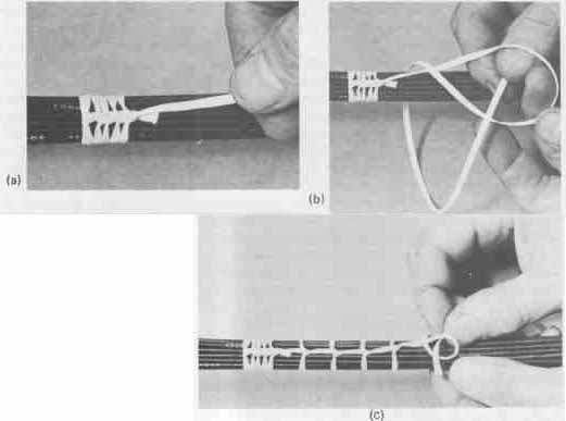
Another method of forming a harness other than continuous lacing is with the use of commercially available cable ties. They consist of a nylon strap with a locking eyelet. Small closely spaced grooves are on the inside surface of the strap perpendicular to the length of the strap. These grooves will be in contact with the harness when assembled. The cable tie is first looped around the leg to be bundled. The tapered end of the strap is then fed through the eyelet and pulled tightly. The strap is held securely by the locking eyelet, which engages the grooves and prevents the strap from slipping. Excess strap length is cut off with diagonal cutters close to the eyelet. The proper procedure for bundling leads with cable ties is shown in FIG. 12.
Special hand-operated cable tie assembly tools are available to facilitate the use of these bundling aids. One such tool is shown in FIG. 13. It consists of a gripping and cutting head a tension contro4 and an actuating trigger. The tension control, roughly gauged from loose to tight, is set for the desired tension. The specific setting is determined by “feel,” using the trial-and-error method. With the cable tie looped around the harness, the tapered end of the strap is fed through the eyelet and into the gripping head of the assembly tool. Each time the trigger is actuated, the head grips the strap and pulls it for a short distance through the eyelet. It may be necessary to actuate the trigger several times to reach the amount of tension that will firmly grip the leads.
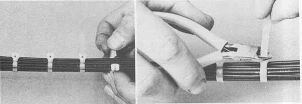
--- FIG.—12 Cable ties are used to bundle leads: (a) insertion of tab
through locking eyelet; (b) trimming excess tab length.
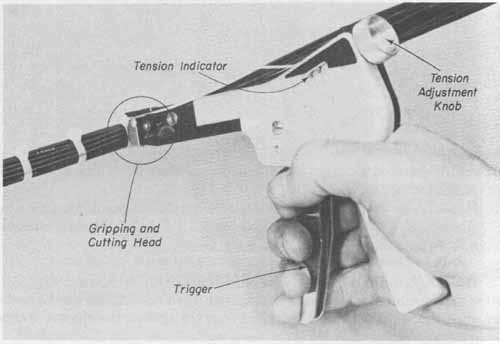
--- FIG.—13 Hand-operated cable tie assembly tool.
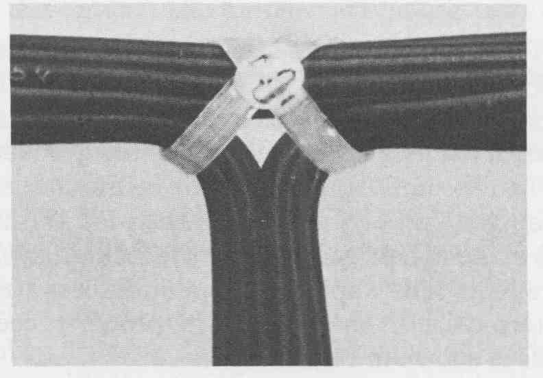
--- FIG.—14 Technique for securing breakout points.
When the preset tension setting is reached, the cutting head shears the strap close to the eyelet. The use of this tool allows for rapid and uniformly controlled cable tie assembly.
Cable ties are positioned at regularly spaced intervals along the harness and at each breakout point. At breakout points, a single cable tie is looped in a crossed fashion around the breakout (see FIG. 14).
6 SHRINKABLE TUBING
Continuous lacing or cable ties for harness construction are the two most popular methods used. Another technique of harnessing employs plastic and elastomer materials classified as heat-shrinkable tubing. This tubing is available in at least 12 different materials, each having its unique properties.
Manufacturers of shrinkable tubing employ special mechanical and thermal means to expand the molecules of the tubing and “fix” them in a strained state. When heated, the strains established during the manufacturing process are relieved, thus returning the tubing diameter to its original size. In addition, the wall thickness, which is reduced during manufacture, returns to its original thickness when heated. Shrink temperatures for some of the common tubing materials range from 175 to over 600°F (79 to 316°C).
In its expanded state, shrinkable tubing is easily slipped over the leads to be bundled after being cut to the required length (FIG. 15a). Shrink tempera ture is achieved with the use of a portable electric heat gun, shown in FIG. 15b, which concentrates heated air completely around the tubing, thus shrinking it and forming a tight fit. This process requires only one or two practice trials to determine the optimum length of time for the application of heat to shrink the tubing to the desired size.
--- FIG.—15 Installation of shrinkable tubing: (a) initial placement
of tubing sections; (b) air deflector allows for uniform heating.
Shrinkable tubing exhibits several desirable characteristics that are not attainable with continuous lacing and cable tie methods. Shrinkable tubing provides a dust-free, waterproof, and an abrasive and oil-resistant covering over the harness as well as the ends of the connectors. Short lengths of shrink able tubing may also be used on a laced or cable-tied harness where abrasion at a particular point could be a problem. The one disadvantage of this tubing is that it can only be used where accessibility will permit.
7. CABLE CLAMPS
When the harness has been completed, it is initially installed into the system. If connectors have been preassembled onto the harness, they are first mounted. All leads requiring soldered connections are then assembled onto the sub- assemblies. The orientation of the installed harness must be such as to protect the wire insulation from abrasion. In addition, the harness must not contact high-temperature components.
The harness must finally be rigidly fastened to the chassis to prevent movement or undue strain on terminal connections. Commercially available cable clamps, such as those shown in FIG. 16, are used for this purpose. These clamps are constructed of nylon or Teflon and are provided with either a clearance hole for typical machine screw sizes or with an adhesive backing for securing the clamp to the chassis. They are available in sizes to accept harness diameters from inch to several inches and provide an excellent means of se curing a harness rigidly to chassis elements.
8. CABLE DESIGN AND FABRICATION
Cable design is less involved than that for harnesses since all leads run the full length of the cable with no breakout points. Therefore, the basic information necessary for the fabrication of a cable is (1) overall length; (2) termination hardware and connectors; (3) type, size and insulation of the wire; (4) type of protective tubing; (5) number of leads; and (6) To and From terminal connections for each lead. This information may be listed in a table similar to the wiring table of TABLE 1, with appropriate modifications to include only the specific information listed above. Similar to harnesses, the addition of leads or terminations once a cable has been completed is a tedious and time-consuming task. For this reason, the wiring table must be developed with care and the cable fabricated in exact accordance with the table.
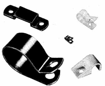
---FIG.—16 Typical cable clamps.
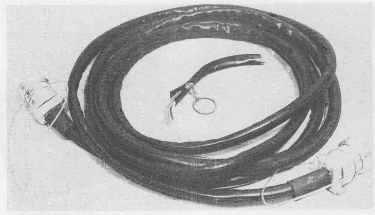
---FIG.—17 Split-wall (zipper) tubing.
To fabricate a cable, the leads must first be run through flexible tubular insulation. With the ends of the tubing secured in the ends of the connectors, the leads become completely enclosed, thus reducing undesirable environmental effects. The two basic styles of tubing are the solid and split-wall (track closure) configurations. The split-wall type is shown in FIG. 17. When solid-wall tubing is used, a wire snake may be necessary. One end of each lead is secured to the wire snake and all are pulled through the tubing simultaneously. When cables are extremely long, this process can become very difficult. For this application, split-wall tubing is preferred, since it can be opened along its entire length. The edges (track) of this tubing are designed to interlock when forced together through a zipper action, thereby completely enclosing the leads that are laid into it. If the cable is to be bent to a small radius when installed, a sealer, such as ZT Sealer,* is spread onto the mating edges of the track before they are interlocked. This sealer causes the track to chemically fuse, preventing the tubing from opening when bent.
After the leads have been enclosed in the tubing, one connector is soldered on one end to secure both the tubing and all leads at that position. The flexible tubing is then forced back from the opposite lead end to allow accessibility for soldering leads to the remaining connector. It is important to point out that all hardware associated with the installation of the connectors (locking collars and seals) are slid over the tubing before the lead ends are soldered. After the leads are soldered, the tubing is smoothed into position and secured with the locking collar of the connector. When an additional measure of sealing is desired at the point where the leads enter the connector, a length of shrinkable tubing may be positioned to extend from the tubing onto the rear portion of the connector.
Prior to placing cables into service, it is good practice to test each one for electrical problems. Despite the advent in recent years of automated test equipment, prototype cables and harnesses require simple continuity tests, thus requiring the familiar ohmmeter. Together with the wire list shown in TABLE 1, the ohmmeter provides an effective method of testing of shorts or opens in a cable.
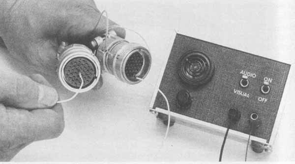
---FIG.—18 A simple cable tester can check for continuity with either
an audio or visual display.
Each individual wire is checked by placing the ohmmeter between the appropriate pins and the ends of the cable as indicated on the wire list (see FIG. 18). If continuity is confirmed, one lead from the ohmmeter is then used to check all the other terminations in the cable to ensure that no shorts exist. After each termination is tested and found correct, it is checked off on the wire list to so indicate.
EXERCISES
A. Questions
1 Explain the difference between a cable and a harness.
2 Why should a harness not be used on high-frequency circuits?
3 Why do harnesses lend themselves ideally to mass-production applications?
4 What is the minimum information that should appear on a wiring table?
5 What is the purpose of a functional wiring layout?
6 How are wire crossovers minimized in harness fabrication?
7 What is the optimum distance of running hitches when fabricating a harness?
8 How are breakout points more easily established with the use of cable ties?
9 What is the range of temperatures required for common shrinkable tubing?
10 What are the advantages of using shrinkable tubing compared to lacing and cable tie methods?
11 What is the advantage of using zipper tubing compared to solid-wall tubing?
B. True or False
Circle T if the statement is true, or F if any part of the statement is false.
1 Harnesses find wide application in high-frequency circuits. T F
2 A cable has no breakouts. T F
3 A breakout is defined as two or more laced leads leaving any portion of a harness assembly at the same breakout point. T F
4 A harness assembly drawing is used to construct both the harness jig and the actual harness. T F
5 A harness assembly drawing should be constructed using a 1: T F
6 A splice in a laced harness is permitted as long as it is formed neatly. T F
7 Harnesses can be fabricated more quickly with the use of cable ties. T F
8 Only one cable tie is required to firmly establish a breakout point in a harness. T F
9 The leads in a harness are stripped and tinned prior to lacing. T F
10 Shrinkable tubing may be used on a laced or cable-tied harness. T F
C. Multiple Choice
Circle the correct answer for each statement.
1 The harness assembly drawing is a (top, bottom) view of the harness.
2 Individual leads leaving a leg at regular spaced intervals in a harness is called a (breakout, fanout).
3 The (girth, locking) hitch is generally used to begin the lacing process.
4 A requirement for fabricating a harness is (an assembly drawing, a functional wiring layout).
5 Split-wall tubing was made to be used in the fabrication of (harnesses, cables).
D. Matching Columns
Match each item in column A to the most appropriate item in column B.
COLUMN A | COLUMN B
1. Zipper 2. Cable ties 3. Trunk 4. Bobbin 5. Girth 6. Leg |
a. Lacing hitch b. Minor run c. Major run d. Nylon strap e. Split-wall tubing f. Shuttle |
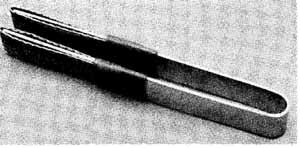
---FIG.—19
E. Problems
1. Fabricate a lead cleaner such as that shown in FIG. 19. Use a – by 10-inch strip of 16-gauge aluminum, two 5-inch lengths of f-inch-wide copper braid, and two 1-inch lengths of shrinkable tubing.
2. Determine the spacing between running hitches when bundling the trunk of a harness that consists of 23 leads. Each lead is No. 18 AWG stranded conductor with an insulation thickness of inch.
3. Determine the suitable expanded inside diameter of shrinkable tubing to secure a bundle of leads such as described in Problem 25.2.
4. Construct a lacing shuttle such as is shown in FIG. 6. The shuttle is to be fabricated from a 1- by 2k-inch blank of 16-gauge aluminum. A 90- degree notch is to be sheared into each end to a depth of inch. Break all sharp points and edges with an appropriate file.
5. Using TABLE 1, fabricate the harness shown in FIG. 3. Draw the harness contour on a sheet of 17- by 22-inch grid paper. Secure the contour drawing onto a board with masking tape. Nail brads into the board about the contour where necessary to position and tie off all wire runs given in the table. Once all wire runs are in place, form the harness with nylon lacing tape.