Apart from a multimeter and perhaps an oscilloscope, a resistive dummy load of 4, 8 or 16 ohms impedance capable of dissipating up to 100 W is just about the most useful item of test equipment the audio enthusiast could have.
Design by Andrew Kay.
The project staff at ETI have spent some considerable time over the past few years developing a variety of amplifiers. The fruits of these labors have been duly published and enjoyed by many readers. However, we've always lacked a decent dummy load for such work and have sort of made do. Whilst jury-rigging such things is in the finest traditions of electronic design and development, the (more than) occasional mishap is not just a frustrating interruption but often a decided nuisance.
In the meantime, a freelance associate of ours, Andrew Kay, had desired exactly the same thing--'a decent dummy load'. He purchased a batch of one watt 1% resistors and made a 50 W dummy load. But, he figured, why not have a little more versatility and make two the same, allowing parallel and series connection to obtain a 4 ohm, 100 W dummy load or a 16 ohm 50 W dummy load as well as a twin 8 ohm 50 W dummy load enabling testing of both channels of a stereo amplifier at the same time! Frankly, we don't know why we didn't think of it earlier ourselves.
Multi-resistors
By paralleling resistors of an appropriate value, one can obtain an effective resistance of the wanted value and wattage rating. Now, the cheapest, most common power rating for carbon film resistors is one watt (1 W). To obtain a 50 watt resistor, 50 would need to be paralleled. To obtain an effective resistance of 8 ohms, each 1 W resistor would have to have a value of 400 ohms. The nearest preferred value is 390 ohms. Fifty in parallel would give an effective resistance of 7.8 ohms which is about 2 1/2% lower than the ideal 8 ohms.
However, 49 in parallel gives an effective resistance of 7.959 ohms- -less than 1/2 % out. if you require the tolerance of your load to be within 1%, or better, then you'll have to use 1%, 1 W resistors. If you only require a tolerance of ± 5%, then the common 5%, 1 W variety will do the job. Either way, you're better off using 49 resistors so that the effective resistance of the load comes closer to the ideal 8 ohms.
The dummy load described here consists of two 8 ohm loads, which enables the testing of both channels of a stereo amplifier. The idea itself is not all new or original, having been used by radio amateurs for years to obtain resistive dummy loads for terminating radio transmitters while they are on test. The advantages of a dummy load for any kind of power source are: the power source (in this case an AF power amplifier) is presented with an ideal resistive load of the correct value the chances of damaging expensive loudspeakers during experimental phases of construction are eliminated completely silent 'full power' testing is made possible even for extended periods of time; which is great for public relations (and your ears.)
Parallel Approach
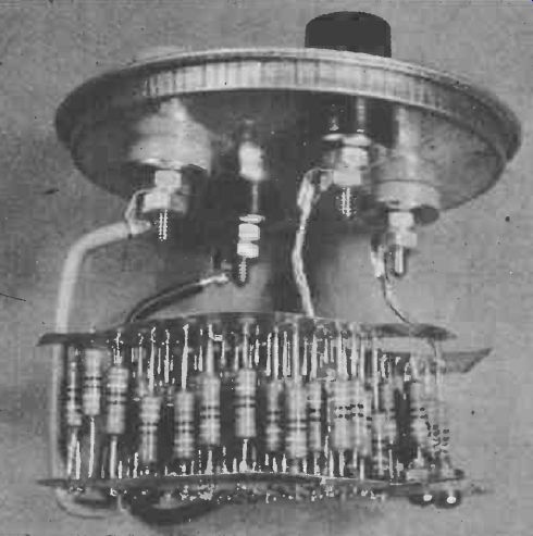
Essentially each dummy load consists of 49 high stability 1% metal film resistors connected in parallel to give a terminal resistance of 8 ohms.
Since the tolerance rating of the resistors is 1% the upper tolerance limit for the combination is 8.04 ohms and the lower limit is 7.88 ohms. The number of resistors to be bought was a compromise between the desire for a result of exactly 8 ohms and the need to keep the cost to a minimum.
Obviously, larger numbers of resistors could be used (say 70 x 560 ohms in parallel) and the reader can easily vary the circuit to suit the pocket and availability of the resistors.
Separate terminal posts are provided for each load so that two separate 50 W sources can be terminated in 8 ohms each or the two halves may be connected in series to give a single 16 ohm 50 W load; and, last but not least, parallel connection of the two halves will result in a 4 ohm 100 W load. Because metal film resistors are used there are no inductive effects to worry about such as could occur if wirewound units were employed. The stray capacitances present are so low as to be insignificant.
Construction
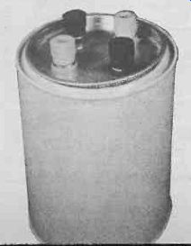
Construction is simple, if somewhat tedious. Lots of soldering is involved! The author used two ordinary household tin cans; one can has a lid (eg a coffee tin), the other is a smaller one of the throw-away type. The top and bottom of the smaller can were used as soldering planes for terminating the ends of the resistors, while the larger can was used to house the project with the lid carrying the terminal posts. Since the coffee tin is virtually leak-proof you could fill it with some kind of insulating fluid such as transformer oil and thereby increase the dissipation capability of the dummy loads.
Tin-plated steel is very easy to solder but the sharp edges are dangerous to careless fingers. Blank copper clad printed circuit board could be used instead but does not withstand heat as well as the plain metal sheet.
The arrangement of tin cans may not seem very glamorous but it is highly effective and very cheap--the whole cost for the project comprises about £4.50 for the resistors and about £1 for the terminal posts. The tin can housing can be spray-painted and the terminal posts labeled and marked to suit individual needs.
Before starting, choose a medium-sized tin with a re-sealable lid for the case and select a tin can of smaller diameter which will fit easily into the coffee tin. About 8 or 9 centimeters in diameter should be fine for the smaller tin can. Using a can opener, remove the top and bottom of the smaller can and discard the contents (maybe you should eat the contents... ). Also, discard the remaining cylindrical portion of the can! Mark up one of the tin-plated discs so obtained with a grid of 10 by 10 lines as shown in Fig. 1 to give 100 intersections. Allow a space of about 10 mm along one diameter as shown. This will allow the discs to be cut in half later. Clamp both discs together on to a drill bench or a block CUT ALONG of wood, ensuring that they are exactly superimposed. Drill a hole on each intersection of the previously marked lines. Make the holes slightly larger than twice the diameter of the resistor leads; this will assist assembly later on.
Take care that your hands are kept clear during drilling since if the drill bit grabs, the two tin discs will whirl around very much like a meat slicer, and almost as sharp! Only 98 holes are needed so don't get carried away.
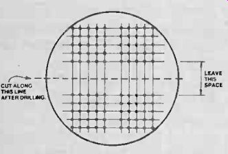
Fig. 1 Drilling and dining details for the tin-plated discs obtained from
a small can.
When the holes are drilled, cut the two discs along the middle space left along one diameter so that you end up with four half discs each with 49 holes.
Tin the area around each hole with solder and proceed with assembly.
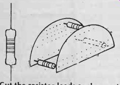
Fig. 2 Cut the resistor leads as shown at left and then solder three resistors
to two half-discs as shown to make a rigid assembly.
Lead Time
Trim all the resistor leads as shown in Fig. 2 so that one lead is longer than the other on each component. Take two matching half-discs and, using three resistors, assemble a rigid structure as shown in Fig. 2. Insert the resistors, one row at a time, in between the two tin plates with the leads poking through the holes. If you insert the longer lead of each resistor into its hole first, the other end should be short enough to allow maneuvering into the hole in the second plate. After one row of resistors is in place solder all the leads of that row on both plates, then proceed with the next row.
Repeat the assembly for the second half of the unit, then trim all excess leads flush with the surface of the tin plate.
Connect an ohmmeter between the plates of each load --the reading, believe it or not, should be pretty close to 8 ohms. Inspect all solder joints and resolder if the reading is not correct.
Install the four terminals in the lid of the tin using one red and one black terminal for each half of the unit. Lay the two assembled resistor pads side by side as shown in Fig. 3. Using fairly stiff copper wire connect the upper plates to one terminal each. Use the same colour terminal for both plates as this will be important later if the loads are to be connected in series or parallel. Using the same sort of wire, but insulated, connect the lower sides of the resistor assemblies to the other two terminals. You should finish up with an assembly which will be supported under the lid of the tin and which is so positioned as to allow it to be inserted into the container for the lid to be sealed.
To prevent the two halves of the load from shorting together, install an insulating spacer between them using a scrap piece of copper-clad board or matrix board. If using the PCB material, ensure that enough copper is removed to insulate the two halves from each other. If using the matrix board, you will have to drill a couple of additional holes and use small screws to attach the spacer to the resistor assemblies.
Before inserting the assembled unit into the container, mark the lid to indicate which terminals are connected by the resistive pads.
To test the unit, connect each load across a known working amplifier or if this is not convenient, use a car battery (not more than 12 V) as the driving source. If using an amplifier, connect an AC voltmeter across the load under test. If you can use a sinewave generator to drive the amplifier, all the better. Adjust the amplifier volume control to give about 10 to 15 V across the loads. Check by feeling the resistors with your hand that they are in fact warming up. Increase the output of the amplifier until the voltage across the loads is about 20 V. This should result in the resistors getting quite hot after a couple of minutes.
If using a car battery, connect the two loads in parallel and connect the battery across them. Check the current drawn; it should be approximately 3 A with a 12 V battery.
When testing is satisfactorily completed, install the whole assembly into the container and press down the lid. If you plan to use the loads continuously, fill the container with insulating oil before assembling.
BUYLINES
Every mail order supplier we know will sell you the resistors and terminal posts! It's worth phoning a few to get the best price on large quantities, however. Try Technomatic and Bi-Pak for starters.
PARTS LIST
98 off 390R 1 W 1% or 5% resistors (or similar combination, eg 140 off 56081 W 1% or 5%). Use carbon film for low inductance. Four terminal posts, two red, two black.
Two household tins--see text.
= = = =
Electronics Today (UK print magazine)
Also see: Link |