Normally pots are used to control voltage, but as Keith Brindley explains, the TDA 1074 uses voltage to control pots. This circuit design feature should put new life into your hi-fi.
In the June issue (pp 70-74) we saw how two of the chips in Mullard's range of voltage-controlled audio ICs could be used for signal switching and fixed-slope filtering in remote, touch, or computer-controlled preamplifier applications. The next stage in such a preamplifier will consist of volume and tone circuits.
In an ordinary, manual preamplifier these functions are provided by potentiometer control --the pot simply acting as a variable potential divider of the signal. Inevitably, because the pot is mounted away from the PCB (or at best, on it), a loop is formed through the pot which tends to pick up interference.
Techniques such as screened cabling, PCB mounting of pots and so on reduce the amount of interference pickup, but only to a limited extent. Electronic potentiometers, however, can create a further, significant reduction in interference, since they are voltage-controlled and have no interference loops.
Mullard's IC, the TDA1074, can act as four voltage-controlled pots ganged into two completely separate double electronic pots. Use of the IC thus allows the active controls to be at PCB level, and coupled with good board design this means that few or no interference loops will be formed. Control of the 'wiper' position of the pots is by DC control voltage, making them an ideal choice in the volume and tone control stage of a remote, touch, or computer-controlled high-fidelity preamplifier.
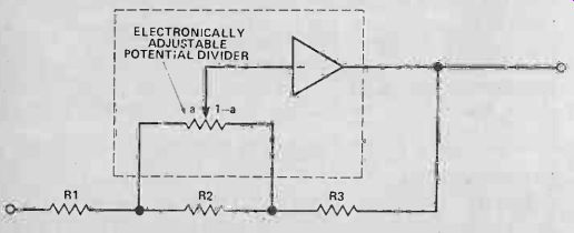
Figure 1. One of the two basic ways in which the gain block (the part of the circuit shown within the broken lines) of the TDA1074 can be used as a voltage-controlled potentiometer.
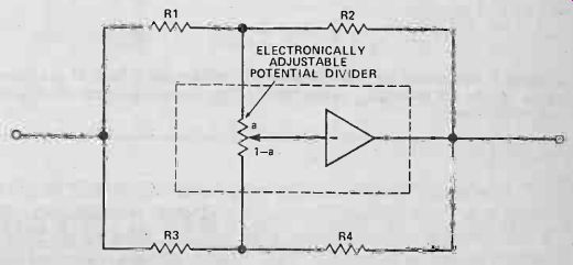
Figure 2. The second way in which a gain block of the TDA1074 can be used to form a voltage-controlled potentiometer.
Go For The Pot
Mullard's principle of voltage-controlled potentiometers is quite straightforward: the position of the 'wiper' of a potential divider within the IC is controlled electronically by a DC control voltage and the output from this wiper feeds an inverting op -amp. Figures 1 and 2 show how this principle can be used in two ways. In both configurations we can divide the potential divider into two parts: alpha, and (1 -alpha ) where alpha is the ratio of resistance to one side of the wiper and (1 -alpha) is the ratio of resistance to the other side.
Inserting imaginary values of resistors (R1 = R3 = 10k, R2 =1 MO) into Fig. 1 we can calculate the gain (G) of the circuit. By inspection, when alpha = 1, ie when the wiper is at the far right of the potential divider,

R3 G R1 + R2 10k 10k + 1MO 1 100
The negative sign is required because we are using an inverting amp. Similarly, when alpha = 0, R2 + R3 1 M0 + 10k 1 G R1 10k 100
So the range of gain in this imaginary example is approximately ±40 dB.
The gain of the circuit of Fig. 2 can also be calculated by inserting imaginary resistor values
(R1 = R4 = 10k, R2 = R3 1 MO). When cc = 1 R4 10k 1 G = -R3 IMO -100 = -40 dB
And when of = 0, R2 1MO G R1 10k
= 1 100 = + 40 d B
(Once again the outputs are inverted).
So in this imaginary example, the range of gain is also ±40 dB.
Setting The Tone
These two examples show how voltage-controlled amplifiers/attenuators can be easily made. Their frequency responses will be level. In contrast, the frequency responses of tone controls are not level--the circuit will have different gains at different frequencies. For example, turning the treble control up in an amplifier system increases the amplitude of the higher frequency components in the applied signal; turning the control down decreases the amplitude.
The circuits of Figs. 1 and 2 can be adapted to form variable-slope filters such as tone controls, simply by replacing one or more of the resistors in the circuits with capacitors. Of course, a capacitor has a 'resistance' (correctly speaking, a reactance) which varies with frequency, so the gain of the circuit will also vary with frequency. Replacing all resistances with Z values (where Z can be the resistance of a resistor or the reactance of a capacitor, both measured in ohms) the gain of the circuit of Fig. 1, at any one frequency, will vary between the limits ...
Z3 Z2 + Z3 G
-=Z1 + Z2 to Z1
... depending on the position of the potential divider wiper.
Similarly, the gain at any one frequency of the Fig. 2 circuit will vary between the limits GZ2 Z4 27.1 to Z3 depending on the position of the wiper. In other words, the circuits can be used to form voltage-controlled variable-slope filters. Such filters will be discussed later in the applications section.
Figure 3 shows a simplified internal circuit of the TDA1074 built up using the basic op-amp stages of Figs. 1 and 2. Op-amps 1 a and 1 b form one double-ganged pot, whose output is at Vss/2.
Decoupling/smoothing capacitors are required from pins 1 and 8 for this voltage.
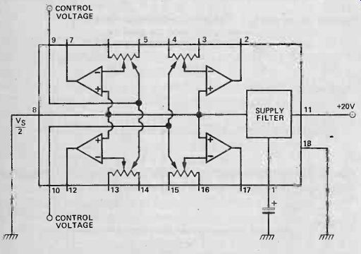
Figure 3. Simplified internal diagram of the TDA1074. Four of the basic
gain blocks are internally connected as two, double-ganged, electronic potentiometers.
Maximum control voltage range (applied directly to pin 9 or 10) is ±1 V of half-supply (eg using a supply voltage of say, 20 V, the control voltage range is 911 V) but most gain change occurs within ± 200 mV of Vss/2. The most convenient way to derive a suitable control voltage range of 9V8 to 10V2 is by using a voltage divider from the power supply and the output from pin 8 (the filtered Vs5/2 supply). Fig. 4 shows the idea.
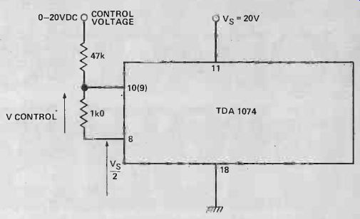
Figure 4. A simple potential divider circuit of only two resistors means
that a control voltage range of 0 -20 V DC can be used. Other voltage ranges
can be selected by a suitable choice of resistors.
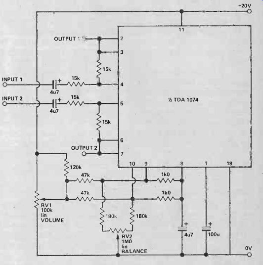
Figure 5. Stereo volume and balance controls obtained with only one half
of the TDA1074.
Applications
Volume and balance controls can be made by straightforward adaptation of the gain block circuit of Fig. 1. By having no resistance for R3 the maximum value of gain becomes R2/R1, and the minimum, 0. If R2 = R1, as in Fig. 5, then the circuit acts as volume control with a range of zero to unity gain.
Balance between two parallel audio channels is most easily achieved by adjusting the ratio of DC control voltages between the two. In Fig. 5, pot RV2 reduces one control voltage down toward 0 V more than the other, depending on the position of its wiper.
A superior balance control is achieved by separating it from the volume control into its own circuit. Figure 6 gives the circuit with suggested component values. At a control voltage of 10 V, the two halves of circuit each have unity gain. At the extreme ranges of the control voltage, one channel will have a gain of about 2 (+6 dB), as opposed to 1/30 (-30 dB) for the other.
Mixing it
The basis of a high-quality voltage-controlled stereo mixer is shown in Fig. 7. The standard gain block is used to increase the level of one signal whilst decreasing the level of the other. At an input control voltage of 10 V the gains of the circuit are the same. Stages can be cascaded if required.
Maximum gain of each input is defined by the ratio of feedback resistor to input resistor on that input, eg R2/R1, R4/R3... Unity gain is thus obtained when R2 = R1, R4 = R3 and so on.
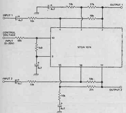
Figure 6. Superior balance control. A control voltage input of 10 VDC gives
equal signal gains from both channels.
A variable stereo image width control is shown in Fig. 8.
This can be used in place of a stereo/mono switch if fully variable control of signals is desired between the two extremes of stereo (complete separation) and mono (complete crosstalk). The effect is produced by feeding a controlled portion of the input of one channel to the input of the other. Varying the control voltage alters the amount of this crosstalk so maximum and minimum separation occurs.
Voltage Controlled Filters
By replacing certain resistances with reactances as explained previously, bass and treble tone controls can be formed. The treble controls in Fig. 9 are, in fact, adaptations of Fig. 2 with capacitors added (in parallel with R2 and R3 of Fig. 2), forming frequency dependent potentiometer. Similarly, the bass controls in Fig. 9 are taken from Fig. 1 (with a capacitor in parallel with R2). Frequency response curves of the whole circuit are given in Fig. 10. Maximum cut and lift of the controls are seen to be about ±14 dB at 60 Hz and 10 kHz and are completely variable, electronically, between these extremes.
Finally, to show that the TDA1074 can be used in other voltage-controlled filter applications, a presence control is given in Fig. 11. Presence is an effect where amplification of frequencies around 1 kHz takes place with little or no amplification of other frequencies. The effect is used mainly in live music work, where it can apparently boost (give presence to) the level of a singer's voice, compared with the backing music. Frequency response curves for the circuit are shown in Fig. 12.
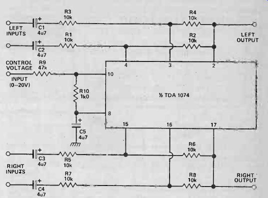
Figure 7. Voltage-controlled stereo mixer application using the TDA1074.
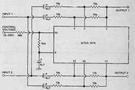
Figure 8. A completely variable stereo/mono control.
A full stereo output is obtained when the applied control voltage is 20 V DC. Mono output occurs with a control voltage of 0 V DC.
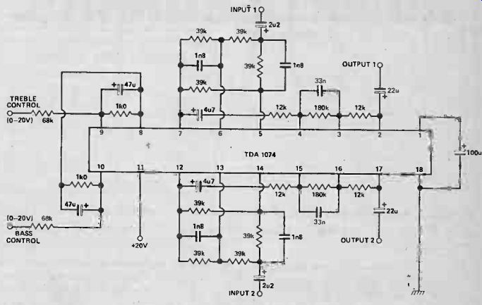
Figure 9. Bass and treble controls obtained by replacing chosen resistances
from Figs. 1 and 2 with reactances.
In conclusion, it is apparent that many more applications of this IC are possible and depend only on the designer's ingenuity. You can see from the basic gain block circuits of Figs. 1 and 2 how easy it is to make voltage-controlled amplifiers and filters by the simple choice of resistances or reactances.
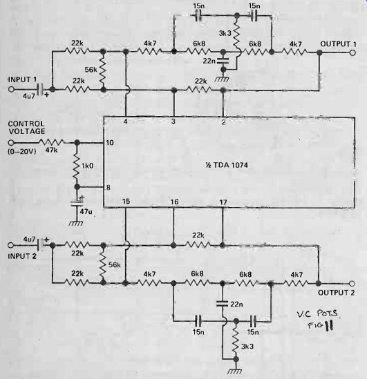
Figure 11. Voltage-controlled presence control to boost frequencies around kHz.
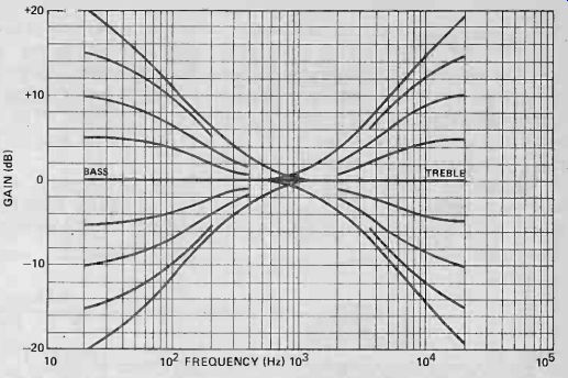
Figure 10. Frequency response curves obtained with the circuit of Fig. 9.

Figure 12. Frequency response curves of the voltage-controlled presence circuit of Fig. 11.
= = = =
Electronics Today (UK print magazine)
Also see: Link | --Dummy Load