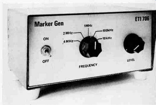
Accurate crystal-controlled markers for tuning and aligning communications receivers.
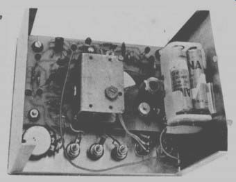
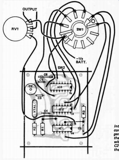
----------- Internal view of the completed marker generator. Note that the board is mounted with the crystal and C2 towards the top of the box.
A LIMITATION of most low priced communications receivers and conventional radios is that tuning accuracy cannot be guaranteed. This means that when waiting for a short-wave station to come on the air we may well miss the beginning of the transmission because we have been tuned to the wrong frequency. The traditional method of overcoming this problem has been to use a marker generator or crystal calibrator. Such instruments generate a series of accurately known and harmonically related signals which are tuned by the receiver in order to determine the accuracy of the dial. The marker generator may also be used to perform the periodic calibration and alignment required by most sensitive receivers.
Although it is possible to build a generator which could be set to any desired precise frequency this approach is uneconomical. The more practical method is to have an oscillator running at an accurately known frequency and to generate harmonics of this frequency. For example a basic frequency of 1 MHz would have harmonics at 2 MHz, 3 MHz, 4 MHz .... and so on.
The marker generator must supply a stable and accurate signal without the necessity of elaborate initial setting up. This requirement leads to the obvious need for a quartz crystal as the basic frequency-determining element.
A slice of quartz crystal has the property that when a voltage is applied to either side of the crystal, the crystal will be mechanically strained and conversely, when mechanical strain is applied a voltage appears across the crystal. The crystal has a natural frequency of resonance and it is thus equivalent to a tuned circuit with a very high 'C I'. The cheapest available crystals operate at 4 MHz and to obtain the frequency intervals that we require we used CMOS ICs to divide down from the higher frequency. To ensure maximum operating speed the CMOS ICs need to be operated from a 10 volt supply. Some exceptional devices will work on six volts but the level of higher harmonics is then reduced somewhat.
To cover as much of the dial as we can in an effective manner the harmonics should be spaced reasonably close together and should extend to 30 MHz. Ideally a harmonic should fall within the passband of a receiver no matter what frequency is tuned. We therefore selected a minimum spacing of 10 kHz as being the most practical. Unfortunately the inaccuracies of many receivers can, in the high bands, exceed 200 kHz thus several harmonics may be within the pass-band at any one time making it impossible for the operator to determine to which harmonic he is tuning. To overcome this problem the marker generator is switchable to provide harmonics spaced at intervals of 4 MHz, 2 MHz, 1 MHz, 100 kHz and 10 kHz.
To produce the series of harmonics required it is necessary to generate a series of very narrow pulses at a repetition rate equal to the spacing required. That is, 10,000 narrow pulses per second will produce the harmonic series 10 kHz, 20 kHz, 30 kHz up through 29 990 kHz and 30 000 kHz.
-----------
HOW IT WORKS -- ETI 706
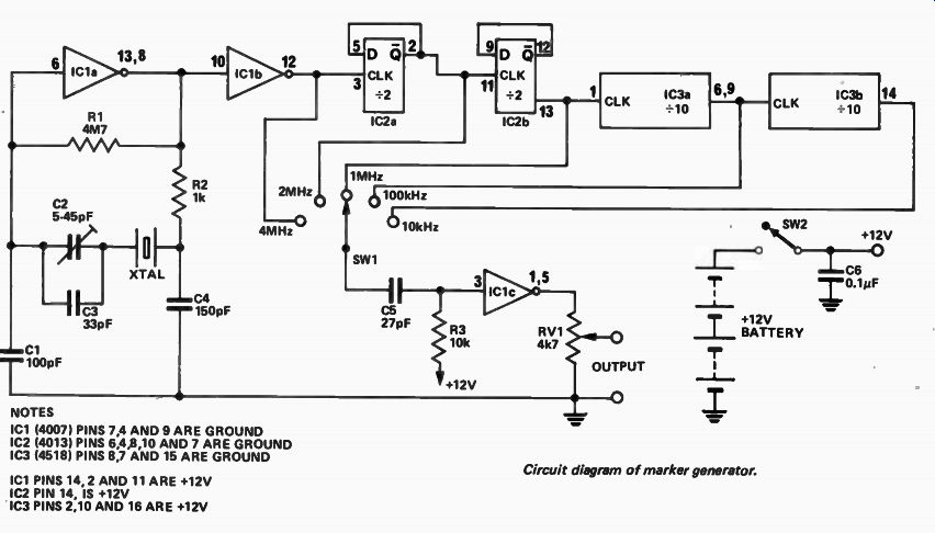
The marker generator is a constant-frequency oscillator driving into a CMOS divider chain.
Switchable outputs from the divider chain are selected to drive a pulse generator.
The oscillator is IC la in which R1 biases the IC into linear operation.
The crystal determines the basic frequency of operation at 4 MHz in conjunction with C1, 2, 3 and 4 which appear to the crystal as one parallel capacitor. The capacitor C2 is used to tune the oscillator exactly to frequency as explained in the text.
The resistor R2 adds extra phase shift but also reduces the gain. Thus if the oscillator is slow in starting reducing R2 may help. The output of the oscillator is buffered from the rest of the circuit by Id/b.
IC2 is a CMOS dual type D flip flop that divides the 4 MHz by four to provide an output of 1 MHz, the 2 MHz also being brought out.
A further dual division by 10 is provided by IC3 which therefore provides outputs of 100 kHz and 10 kHz.
The required output is selected by SW1 and applied to C5 and R3 which differentiate the squarewave output of the divider. The waveform is then amplified and squared by IC1/c to provide an output train of narrow pulses, the amplitude of which may be varied by means of RV1.
----- ---
SPECIFICATION
Harmonic Spacing
Harmonic Range
Accuracy
Five switchable outputs 4 MHz, 2 MHz, 1 MHz, 100 kHz and 10 kHz.
useable to 30 MHz dependent on calibration.
----------------------
CONSTRUCTION
We mounted our unit in a commercially available aluminum box having dimensions of 150 mm wide by 75 mm high and 100 mm deep. The printed-circuit board is mounted on the rear panel of the box but spaced from it by four 19 mm long machine screws. Also mounted on the rear panel are the two output terminals.
The two switches and the potentiometer are mounted on the front panel whilst the battery holders are clamped to the bottom of the box by means of a clamp made from a scrap piece of aluminum.
With the exception of the ICs, mount all components and fit all links to the printed-circuit board. After checking that all are correct, mount the ICs, double checking their orientation before soldering. Fit all flying leads to the board allowing about 150 mm of free length.
Drill the box with all the required holes and fit all the components such as the switches, the potentiometer and the output sockets. Fit the printed-circuit board to the rear panel with C2 to the top of the box and route the leads to their respective points as detailed in the component overlay. Note that one of the screws through the wafer of SW1 has an earth lug underneath it which is used as the common earth point.
Fit the batteries and connect them up but do not switch on until a final wiring check has been carried out. Ten minutes of your time at this stage could save you the cost of a new set of ICs.
----------------------
PARTS LIST - ETI 706
R1
Resistor 4M7 1 / 4 W 5% R2 1k R3 10k " RV1
Potentiometer 4k7 lin
C1
Capacitor 100pF Ceramic
C2 9. 5-45pF Philips 2222 808 91503 C3 .. 33pF Ceramic C4 .. 150pF Ceramic C5 91 27pF Ceramic C6 .9 0.112F Ceramic IC1
Integrated Circuit reE ( gl ig IC2 4518 ¡CMOS IC3 XTAL one 4.0000 MHz quartz crystal 30pF load SW1 Rotary Switch 1 pole 5 position SW2 Toggle Switch SPST One pair of Terminals PC Board ETI 706 Aluminum Box 150mm, 75mm, 100mm.
Two knobs
Eight AA size batteries
Two 4xAA size
Battery Holders
Nuts and Bolts.
-----------------
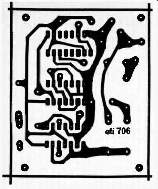
-------------- Printed-circuit layout. Full size 70 x 58mm.

USING THE GENERATOR
Say for example, that we wish to tune a signal that we know to be on 13 250 kHz. First select 4 MHz on the marker generator and connect its output to the aerial socket of the receiver. Tune the receiver to the marker which will be found at 12 MHz (third harmonic of 4 MHz). Once located confirm that it is indeed coming from the marker generator by switching it on and off. Now switch to the 1 MHz markers and tune the receiver upwards to locate the 13th harmonic at 13 MHz. Now select 100 kHz markers and tune upwards through two markers to locate 13.2 MHz. Finally select the 10 kHz markers and tune up through a further five markers to locate 13 250 kHz.
Note that it this tuning procedure is carefully carried out it is quite simple to locate any position on the dial with great accuracy.
THE CRYSTAL. Crystals are supplied to work within specified tolerances. The tighter the tolerances the more expensive the crystal. However the crystal oscillator may be placed exactly on frequency (within smell limits) by varying the amount of capacitance in parallel with It.
When purchasing a crystal you must tell the manufacturer what capacitance it will be working with and he will grind your crystal to be within the specified limits when it is used with that particular capacitance. This marker generator has been designed to work with crystals that are ground for 30 pF capacitance.
CALIBRATION
The marker will be sufficiently accurate for most people with C2 set to half value. For those who want greater accuracy the generator must be calibrated against a signal of known accuracy. The PMG transmit a time signal precisely for this purpose and it can be found on 4.5 MHz, 7.5 MHz and on 12 MHz.
The generator may be aligned against one of these frequencies by the zero- beating technique. First tune in the PMG signal and then connect the generator. A whistle will now be heard and C2 should be tuned to the point where the beat frequency has dropped so low that it cannot be heard. The generator is now spot on frequency and it should be noted that this calibration is independent of the receiver accuracy.
--------------