Sensitive instrument for 'A' weighted audio noise and signal measurements.
AN ACCURATE and sensitive ac voltmeter is needed for many audio equipment measurements.
Whilst for example, maximum power output is readily measurable with a conventional multimeter, more complex instrumentation is required for measuring noise output (a measurement required when checking signal/noise ratio). Even signal levels as high as 100 mV, typical output of most pre-amplifiers, are not readily measured with accuracy on a conventional multimeter.
The ETI 128 Millivoltmeter is specifically designed for such measurements whilst also being useful as a general purpose ac/dc voltmeter.
The lowest range, of 300 microvolts FSD, allows measurements to 80 dB below one volt, whilst other ranges allow measurements up to 30 volts ac or dc. These ranges cover most of the measurement requirements of audio work.
When measuring noise levels account must be taken of the non-linear characteristics of the ear. For this reason a network has been incorporated which tailors the meter response-versus-frequency to match the subjective response of the ear.
Such a network is known as an 'A weighting network' and its use provides a measurement which is realistically related to what is heard.
When measurements are made using this network the results must be quoted as being 'A weighted'. Typically this is done by quoting dBA rather than just plain dB.
CONSTRUCTION
The meter is a highly sensitive instrument and for this reason the constructional method given should be followed closely if noise and hum pickup are to be minimized.
D fitt:ibL) O
<-3 VOLTS n U, JC 30 InV 100 rnV 300 mV
-30dB -20 dB -10 dB
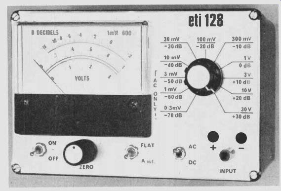
A diecast box is used to house the meter as this provides excellent shielding against external signals. The front panel label is made from 'Scotchcal'. This is a specially prepared sheet of thin aluminum which is coated with a photo-sensitive emulsion on one side. The reverse side has a self-adhesive coating, protected by waxed paper, which is peeled off when the material is to be stuck down. As Scotchcal is only available in bulk, ETI is making available ready-to- use front panel labels made from this material. Should you require one of these labels send $4.00 and a stamped, self-addressed envelope ( minimum size envelope 190 x 127 mm). The meter used in the prototype was from Dick Smith Electronics. It measures 100 x 82 mm but requires to be rescaled. The scale as published on page 19 should be cut out and glued over the existing scale taking care not to let glue or dirt enter the meter movement. Any similar meter may be ...
--------------
SPECIFICATION
10, 30, 100, 300 mV, 1, 3, 30 V. auto-polarity, LED indication.
0.3, 1, 3, 10, 30, 100, 300 mV, 1, 3, 10, 30 V
0 dB = 1 mW into 600 ohms (0.775 V) weighting curves, ac only, flat, ' A' weight
± 3% nominal
MINIMUM READING
Open circuit -76 dB Terminated 47 k -85 dB
POWER SUPPLY
Voltage Current Battery life
+6 and -6 volt ( batteries)
approximately 12.5 mA approx 100 hours ( 8 x 10¹⁵ cells)
eti 128 10 mV
-40 dB 3 mV
-50dB 1 mV
-60 dB O 3mV
+10 dB 10V
+20 dB
+30 dB
RANGES dc ( FSD) ac ( FSD) ACCURACY
-----------------
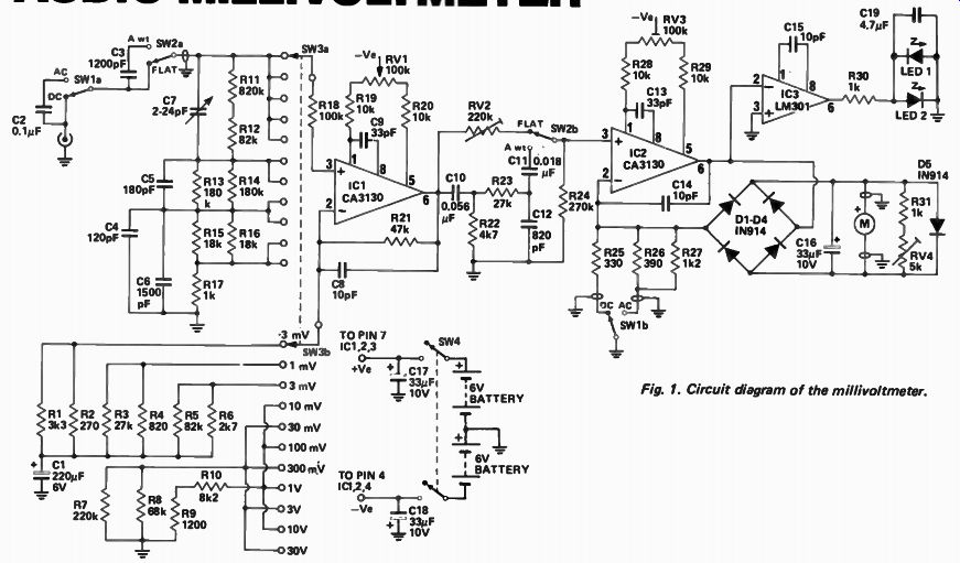
Fig. 1. Circuit diagram of the millivoltmeter.
---------------
HOW IT WORKS - Eti 128
The millivoltmeter may be separated into several sections in order to simplify the explanation of its mode of operation. These are:
(a) Input attenuator.
(b) Input amplifier.
(c) ‘A'-weight network.
(d) Meter drive circuitry.
(e) Polarity detector.
The input attenuator consists of resistors R11 to 17 and capacitors C4 to 7, and gives division ratios of 1, 10, 100 and 1000. The capacitors are required to ensure that the division remains accurate at high frequencies.
The input amplifier is a CA3130 operational .amplifier where the gain is selected by SW3b. Gains of 190, 60, 19, 6 and 1.9 are available which together with the input divider ratios provide the 11 ranges required. The high gain ranges of 190, 60 and 19 are ac coupled, as the temperature stability of the CA3130 will not allow voltages of less than 10 mV de to be used. The output of this amplifier is 60 mV when the meter is indicating full scale on any range. A potentiometer, RV1, is provided to adjust the offset voltage on the CA3130 and thus acts as a zero-set control. Since the offset voltage is affected by temperature this control is available externally.
When measuring noise in audio systems a weighting network is often used to give a measurement which is related to the non-linear response of the ear. The most commonly used weighting is known as ' A' weight and this facility is built into the meter.
The ' A' weight curve is produced by a network that has a three-pole, high-pass filter and a single-pole, low-pass filter. The main section of this filter is formed by C10, C11, C12 and R22, 23, and R24 (two poles). The third pole is due to C3 and the one megohm combined resistance of R11 to R17. This later section prevents saturation of the input amplifier at low frequencies.
Since this filter introduces some loss at 1 kHz, RV2 is incorporated to provide the same loss in the ' flat' mode.
The second IC acts as a meter amplifier. The input signal is rectified by the diode bridge D1 to D4 whilst the amplifier effectively compensates for the diode drops. A preset for offset adjustment, RV3, is provided for this IC. Calibration is performed by adjustment of the shunting resistance, R31 and RV4, across the meter. Due to the full-wave action of the rectifier the meter when on the dc ranges reads uni-directionally regardless of dc polarity. The output of IC2 will however will either be at over one volt positive or one volt negative (voltage drops across the diodes) depending on whether the input voltage is positive or negative.
This is compared by IC3 against zero volts and, depending on polarity, either LED 1 or LED 2 will be illuminated. With an ac input both LEDs will be on. These LEDs are therefore the polarity indicators.
Capacitor C19 removes any high frequency components which could be coupled into the input, as the LEDs are located next to the input socket.
Due to the difference between the average and the RMS values of a sine-wave a slight change in gain is necessary in the ac mode and, this change is made by SW1b.
---------------------
used as long as it has 100 microamp sensitivity.
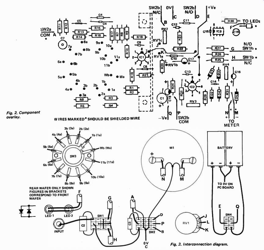
Fig. 2. Component overlay.
WIRES MARKED* SHOULD BE SHIELDED WIRE --- REAR WAFER ONLY SHOWN FIGURES IN BRACKETS CORRESPOND TO FRONT WAFER
-------------
PARTS LIST - ETI 128 R2 R25 R26 R4 R17 R6 RIO R15,16 R21 R8 Resistor 99 R13,R14 R11 R30.31 R9,27 RI R22 R19.20 R25,29 R3,23 R5,12 R18 R7 R24 RV I RV2 RV3 RV4
Resistor
91 99 99
Potentiometer
270ohm 330 ohm 390 ohm 820 ohm 1k 2k7 8k2 18k 47k 68k 2% 2% 2% 2% 2% 2% 2% 2% 2% 2% 1 / 4W ihm 1 / 4W 1 / 4W 1 / 4 W 1 / 4 W 1 / 4W 1 / 4W 1 / 4W y aw C8.14,15 C9,13.
C4 C5 C12 C3 C6 C11 C10 C2 C19 180k 2% 1 / 4W 820k 2% 1 / 4 W C16,17,18" C1 1k 1k2 3k3 4k7 10k 10k 27k 82k 100k 220k 270k 5% 1 / 4W 5% 1 / 4W 5% 1 / 4 W 5% 1 / 4 W 5% 1 / 4W 5% 1 / 4W Ibm 1 / 4W 1 / 4W 1 / 4W 1 / 4W 5% 5% 5% 5% 5% 100k lin rotary 220k Trim 100k Trim 5k Trim C7
Capacitor 2-24 pF Philips 2222 808 00006 10 pF
Ceramic 33 pF Ceramic 120 pF
Ceramic 180 pF Ceramic 820 pF
Ceramic 1200 pF polyester 1500 pF polyester
0.018/IF polyester
0.056/IF polyester
0.1 polyester 4.7 non polarised electro 33 uF 10V electro 220 uF 6V electro IC1,2 Integrated Circuit CA3130 IC3 LM301
D1- D5 Diode IN914, BA318 or similar LED 1,2 5023 or similar with panel mounting SW1,2 Toggle switch 4 pole 2 positions SW3 Rotary switch 2 pole 11 positions SW4 Toggle switch 2 pole 2 positions M1
Meter 100/IA FSD * see text PC Board ETI 128 Die cast Box 6357p Two knobs' One RCA socket Eight AA size batteries Two- 4xAA size battery holders Shield to Fig. 7
---------------
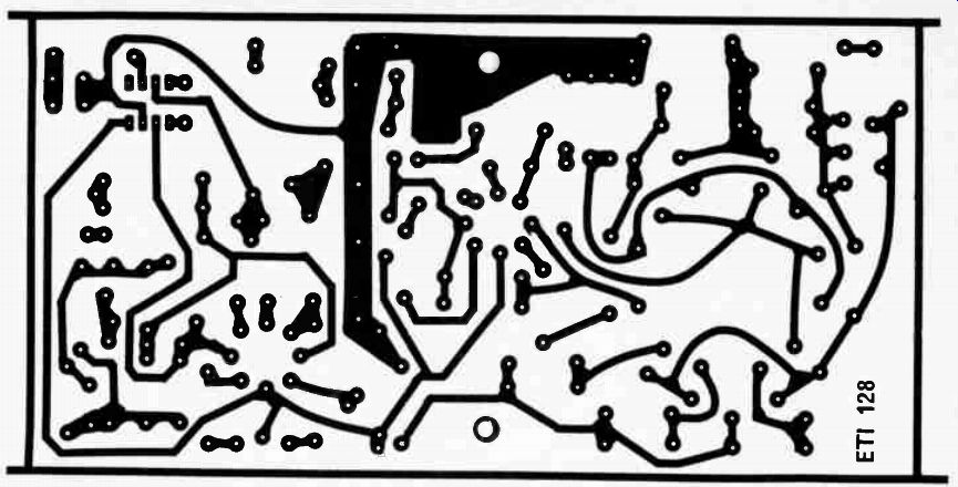
Fig. 5. Printed circuit layout. Full size 170 x 87 mm.
The ac/dc and Flat / 'A' weight switches are four- pole types although only the outer two poles are used. The centre two poles are earthed in order to reduce the capacitance between the two outer poles. Such precautions are necessary to prevent any possibility of instability on the most sensitive ranges. The metal bracket which supports the printed-circuit board also acts as a shield between the meter circuitry and the input stages.
Commence construction by assembling components to the printed- circuit board, making absolutely sure that all are mounted in the correct position and with the correct polarity. This should be carefully done - once the meter is fully assembled, it is very difficult to change components.
Assemble the front panel, fitting all switches with the exception of SW3.
LEDs, potentiometer, input socket, meter, and the shield. The shield passes between the centre two contacts of the 'A'-weighted switch.
Solder a tinned copper lead to each of the 12 contacts on the rear wafer of switch SW3 (about 25 mm long). Feed these wires through the holes provided in the printed-circuit board ( lb to 11 b and Wb) making sure that the wiper contact on the switch goes to Wb and that the other wires are inserted in sequence. Do not solder as yet.
Assemble the printed- circuit board onto the shield and the rotary switch to the front panel. We used a 3 mm stack of washers to space the switch back from the front panel so the control knob would sit down closer to the front panel. Remove any slack in the tinned-copper wires, connecting the switch to the printed-circuit board and ,then solder them to the board.
Now remove the printed-circuit board and switch assembly from the front panel. The switch will now be rigidly held onto the board, and the front wafer can now be wired to the board via further tinned-copper links. Make sure that none of these wires is touching.
Add leads to the printed-circuit in the locations shown on the overlay and reassemble the board and switch assembly to the front panel. The components on the front may now be connected to the board by these leads which should be kept as short as possible without placing undue strain on the wires. The only exception to this rule is the wire from SW1a to SW2a which should be kept reasonably well clear of the second pole of SW10.
This is best done by running the lead down the front panel along the bottom and then back up to SW2a.
Shielded wire should be used where designated on the overlay and wiring diagrams, and this should preferably be of the low capacitance variety.
The LEDs are connected in parallel but in anti-phase, the actual polarities may be determined later if necessary during the calibration procedure.
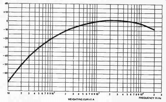
Fig. 4. Curve of ' A' weight response.
CALIBRATION
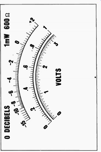
Fig. 8. Artwork for meter (shown full size).
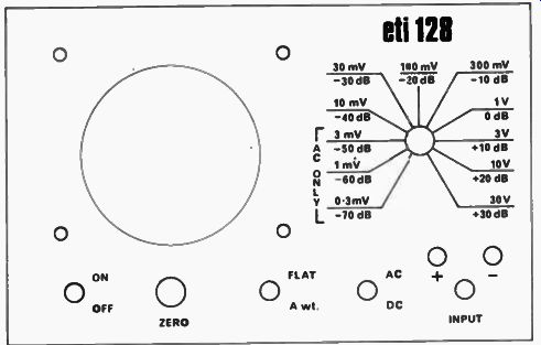
Fig. 6. Front panel artwork. Full size 189 x 121 mm.
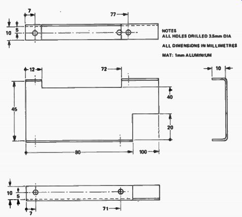
Fig. 7. Details of shield-support bracket.
----------
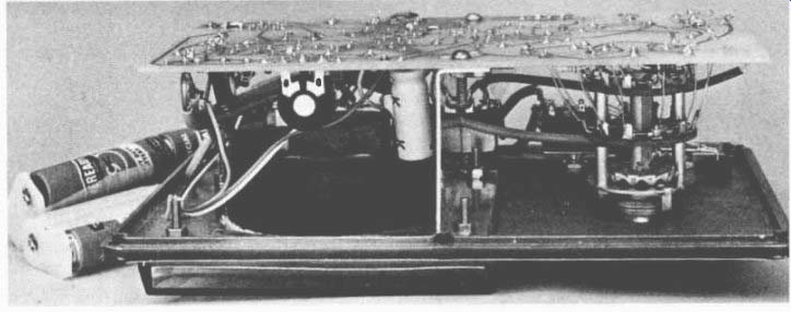
This internal view of the meter shows on the right, how the range switch is wired to the printed-circuit board. Note also the shield.
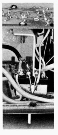
---------- Note how the shield passes between the earthed, centre contacts
of the 'A' weight switch.
Before commencing calibration, check that the meter performs as it should on all ranges by applying known voltages and checking that a deflection of roughly corresponding magnitude is obtained. Also check that the 'A'-weighted switch appears to work as it should.
1. Short the input, select the 3 mV range and switch on.
2. Allow about 5 minutes for the instrument to stabilize thermally and then adjust RV3 to zero the meter.
3. Select the 10 mV range, dc, and 'flat', and adjust the front panel control RV1 to zero the meter.
4. Remove the short from the input, select the 300 mV range and apply an input having a frequency of less than 500 Hz and a level which gives a convenient indication, eg 0 dB. Change the frequency to somewhere between 10 kHz and 50 kHz making sure that the input level is the same in both cases, and adjust capacitor C7 so that the meter reads the same in both cases.
5. Apply an ac input signal and switch between ac and dc. The reading on ac should be about 10% higher than on dc. If it is 10% lower the leads to switch SW1b should be reversed.
6. In the ac mode select ' A'-weight and apply a 1 kHz signal of sufficient level to obtain a 0 dB indication on the 1 volt range. Vary the frequency over the whole audio range and check that the response as shown in Fig. 4 is obtained.
7. Go back to 1 kHz and check that zero dB is indicated in the 'A'-weight mode. Now select 'flat' and adjust RV2 to obtain the same reading.
8. Apply an accurately known voltage with the instrument set to the flat and ac modes and adjust RV4 to give the correct reading.
9. Apply a dc input of known polarity and check that the correct LED illuminates. If not, reverse the leads to the LEDs.
This completes the calibration and the instrument should now give accurate readings on all ranges and at all frequencies within the specified range.