Simple regulated supply provides 4.5-12 volts at 400 mA maximum.

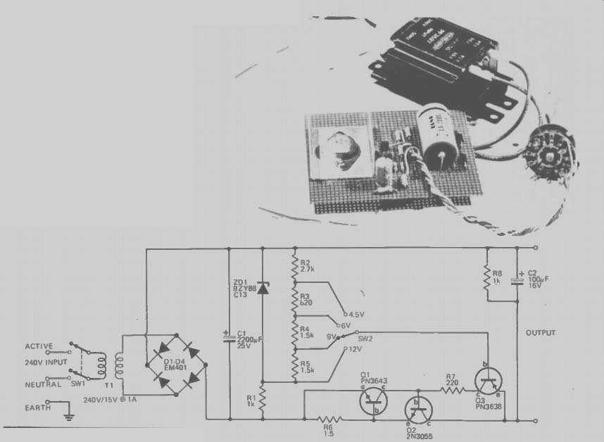
--------Fig. 1. Circuit diagram of the regulated power supply.
---------
SPECIFICATION
Nominal output voltage 12 V, 9 V, 6 V, and 4.5 V Output current 0 - 300 mA Current limit approx. 500 mA
* except when modified for use with organ
--------
PARTS LIST
POWER SUPPLY
ETI 221
R6 Resist,' R7 R3 R1, 8 R4, 5 R2
1.5 ohms 1 / 2 W 5% (2 x 1.5 ohms in parallel for organ)
220 ohms 1 / 2 W 5% 820 " " 1k 19 ef 1.5k 2.7k Q1
Transistor PN3643 or similar Q2 2N3055 Q3 V V PN3638 " D1-04 Diode EM401 or similar
ZD1 Zener diode BZY88C13 " T1 SW' SW2
Transformer 240V/15V e IA DPST 240V switch 4 position single pole switch heatsink for Q2 C1
Capacitor 2200 uF 25V electrolytic
C2 eo 100/IF 16V
Piece of matrix board.
---------
THIS LITTLE power supply provides a range of switch selectable output regulated voltages from 4.5 to 12 volts. The supply will provide up to 400 mA and the output can withstand a short circuit without damage. It is therefore ideal for the experimenter or for use with high drain appliances.
HOW IT WORKS
The 240 V mains voltage is reduced to 15 volts by transformer Ti, and this secondary voltage is then full-wave rectified by rectifier bridge D1-D4.
The output of the bridge rectifier is filtered by C1 to provide approximately 20 volts dc.
The series combination, of Zener diode ZD1 fed by resistor R1, provides a stabilized voltage of around 13 volts which is applied across the voltage divider R2, R3, R4 and R5. Thus a series of reference voltages are generated for the regulator, where the positive rail is fixed and the negative rail is the one that is varied.
Transistor Q3 is an emitter follower where the output (emitter) is about 0.6 V higher (more positive) than the base. The base voltage is selected by SW2 from one of the tappings on the reference-voltage divider. Since Q3 cannot handle the required output current, it drives Q2, a power transistor, which can handle the required load.
When the load exceeds 400 mA (approximately), the voltage drop across R6 forward biases Q1 which turns on and shunts current away from the base of Q2. Thus the regulator loses control and the output voltage falls, limiting the current to 400 mA. As the power dissipated in Q2 under short-circuit conditions is around 10 watts, Q2 must be fitted to a heatsink.
Additionally, resistor R7 limits the current supplied by Q3 to a safe value (for Q3) under short circuit conditions.
If a fully variable supply is required, a 10 k potentiometer should be used in place of the voltage divider. The wiper of the potentiometer is then fed directly to the base of Q3.
-----
-----