(source: Electronics World, Aug. 1963)

By WALTER H. BUCHSBAUM, Industrial Consultant
Accuracy goals depend on applications and the duality of instruments being checked. For any situation. however. satisfactory standards or facilities can be. worked out.
HOW MUCH precision should one expect and how much can actually be realized when one is calibrating test instruments? What standards can be or should be used? How does one go about doing the job or getting it done? The answers to these questions will depend on who wants the calibration performed, the type and quality of the equipment whose accuracy is to be checked, and finally the use to which this equipment will be put. These requirements allow for a wide variation in the results that will be obtained.
Consider one of the less demanding situations. When a technician wishes to check the "B +" in a radio or TV receiver, it is not too important if the nominal 250 volts is actually measured at 262.5 or 237.5 volts. If voltmeter accuracy is 5 per -cent, this alone could account for the 12.5 -volt difference. Variation in line voltage could just as well be responsible. If both line voltage and the meter reading are down, only 225 volts might be read. Deviation would have to be at least this great and probably larger before the technician would begin to consider the possibility of a defect. Although the accuracy requirements here are not demanding, they do exist. If voltmeter error were, say, 10 percent or greater and the user did not know this, he could be misled.
In industrial and military electronics, on the other hand, standards are much more critical. Laboratories, factories, and installation facilities often allocate considerable time and money to the maintenance of test equipment accuracy. In fact, government contracts conventionally carry clauses requiring that all test equipment be calibrated carefully against approved standards at least once every six months.
Reference Standards
In the United States, the exact electrical values for voltage, current, frequency, resistance, capacitance, and inductance are determined by the National Bureau of Standards of the Department of Commerce. Laboratory or secondary standards for these electrical parameters are measured against the Bureau's primary standards at certain regular intervals and are then certified as to their accuracy.
Calibration against certified standards is generally a specialized job. Large organizations maintain special departments for this purpose. Smaller companies send or bring their equipment to nearby laboratories that offer a calibration service.
When such service is required on an outside basis, there should be little difficulty in locating a suitable agency. A request is addressed to the Bureau of Standards, either at Washington, D.C., or to the office in Boulder, Colo. The Bureau will advise where standards of the required type are available in the writer's locality. Each of the three armed services also maintains standards laboratories, which are available to qualified commercial firms. A qualified firm is one that holds a contract with the particular service. It can obtain permission to use standards facilities through the project director.
All major military bases involving electronics maintain standards facilities. Well known bases include the Signal Corps at Fort Monmouth, the Naval Research Laboratories, and the Air Force's Wright Field. For security reasons, the services avoid publicizing all such locations.
In addition, the Air Force maintains a fleet of trailer trucks, each of which carries a complete set of calibrating standards. These mobile laboratories insure precise measurements by making the rounds of various Air Force installations and enabling frequent checks on test equipment calibration.
Although elaborate facilities of this nature are a far cry from what the aforementioned technician would need, many of the problems and principles are common. The technician in a non -critical role is mostly concerned with calibrating a.c. voltage, d.c. voltage, direct current, and resistance on his v.o.m. and v.t.v.m. These will be the most important ones, although there will also be some interest in capacitance, inductance, and frequency. While the required accuracy is much greater in industrial and military applications, essentially the same quantities are involved.
There are a number of references and methods that can be used to insure accuracy in noncritical situations short of comparison against certified NBS standards. Since these involve measures that may be applicable at any level of calibration they will be discussed first.
Basic Meter Checks
Conventional voltmeters, used everywhere for measurement of basic electrical quantities, include the v.o.m. and v.t.v.m. Such instruments are most often specified to have an accuracy of ±3 per -cent for the d.c. scales, ±5 percent for the a.c. scales, and still less for resistance measurements. Many users still overlook the implication of the clearly stated qualification that the specified accuracy is with respect to full -scale reading.
Consider a typical instrument with a 250 -volt d.c. range and a full-scale accuracy of +-3 percent. This means it could be off 7.5 volts not only at 250 volts, but at any other reading on that scale. This same voltage discrepancy would then amount to 7.5 per -cent error if 100 volts is being read. If 15 volts is being measured on the same range, allowable error could be as much as 50 percent.
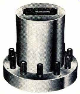
Fig. 1. The Eppley Standard-Cell Voltage Reference, accurate to
.005 ° or better, is tapped in ten steps up to 10.193 volts.
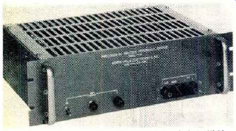
Fig. 2. An a.c.-powered, well-regulated standard, the VS-10 by North Hills
Electronics, provides d.c. reference output.
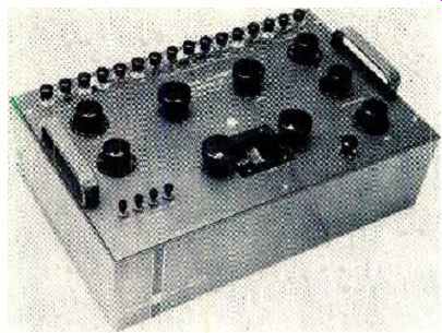
Fig. 3. A universal potentiometer by Leeds & Northup. It combines a
standard voltage reference with precision resistors and a closely calibrated
potentiometer for fine resolution.
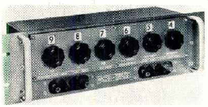
Fig. 4. A resistive voltage divider made by North Hills Electronics. It
is made for use with an external voltage source.
In practice, down-scale accuracy is considerably better than what these figures suggest. If the meter movement were a perfectly linear device, percentage accuracy would be the same at any point on the scale. However, there is some non-linearity in the magnetic meter circuit and some introduced mechanically by the use of springs and weights that balance the movement. Since calibration by the manufacturer is made at the full-scale end, the cumulative effect of errors will be experienced at the low end of the scale. It is therefore preferable, when possible, to use a range that permits readings to fall in the higher end of the scale.
The first step in checking a meter is to make sure that zero indication is accurate. The pointer is set, if necessary, via the external adjusting screw with the instrument in its normal operating position. The instrument should be on its lowest d.c. range, with all test leads disconnected.
Meter bearing balance is checked next. While all calibration will be performed in the instrument's normal operating position, the pointer should show no tendency to stick when the meter is tilted through any of the three major axes. If the pointer does not return to zero after tilting, rebalancing is needed. This is a job for an expert. The instrument manufacturer or an authorized agency should be used.
If balance is good, d.c. voltage ranges are checked by measuring a known voltage source. The most elementary source is the widely available 1.5-volt, carbon-zinc cell which, under certain conditions, will give good accuracy. To begin with, a large cell with screw terminals is preferred to a flashlight size. The battery should also be unused, and reasonably fresh. The nominal voltage usually given for calibration is 1.55 volts. Actually an unused cell about two years old will probably still measure about that much, whereas a fresher one may read about 1.58 volts. However, this range of variation is no more than -±-1%, which is well within the specified accuracy for conventional meters. As a rule, the owner will consider his instrument does not need recalibration if it reads anywhere between 1.5 and 1.6 volts. At worst, error in this case is not likely to exceed ±3 %. Higher d.c. voltages and scales can be checked by combining single cells in series. This is not recommended, however, as it builds up margin for uncertainty. Anyone who is really interested in maintaining a v.o.m. or v.t.v.m., or several such instruments, at good accuracy should consider investing in something better. Mercury cells, for example, are available that will maintain accuracy well within 1 percent over a period of several years. They can be obtained in calibration sets that include several in a single housing, in a series, with taps between cells, Still better, so-called "working standard" meters are available for less than $100. Typical of these is the Weston 931 series, accurate to ±0.5 %. With one such, a single, accurate voltage source is not necessary. The instrument to be checked and the working standard monitor any voltage source or sources simultaneously, and readings at various voltage levels are compared.
On d.c. voltage checks, the lowest range is always calibrated first. In some meters, it is possible to adjust the series resistance here if calibration is seriously off. In most cases, a fixed resistor must be replaced. The next higher range is checked, and so on up to the highest. Resistors added in the voltage divider in each successive range are adjusted, if necessary.
The d.c. current ranges are checked out next, starting with the lowest first If a standard calibration source is not available, a known voltage and precision resistors are required. Current is calculated with Ohm's Law. In addition to the value of the calibrating resistors, input resistance of the meter on each current scale must be considered in calculating current. Possible error introduced by deviation in the latter resistance value can be made insignificant by choosing calibrating resistors whose values are many times higher than that of the meter. Percentage accuracy of the calibrating resistors is determined by the degree of accuracy required. Proceeding from current scale to scale, the values of successive meter shunts are corrected as needed.
Accuracy of the a.c. ranges is affected by frequency and waveshape of the voltage being measured and by components in the rectifier system, as well as by divider resistors.
A reasonably good oscilloscope will make a reliable monitor for checking sinusoidal waveshape and will also indicate voltages in terms of peak-to-peak values, if it incorporates a voltage calibrator or is used in conjunction with one.
Good waveform is needed because the average meter does not respond to r.m.s. value directly. It is calibrated to read r.m.s. equivalent value on true sinusoidal a.c. only. If the scope shows that waveshape of the available 60-cps or 400-cps source is distorted, a good audio oscillator can be used. To convert scope peak -to -peak readings to r.m.s. equivalents, divide the former by 2.83 (or multiply by 0.353).
Accurate readings on a.c. may be due to faults in the a.c. rectifier system in addition to deviations in the divider resistors. Rectifier faults are most likely to show up as inaccuracy in the lower end of all scales. ( Even with a good system, meters tend to be less accurate in down-scale readings than they are on d.c.) Although a calibration resistor is usually included in the rectifier assembly, the best cure for a fault here is replacement of the entire system with a new assembly obtained from the meter manufacturer.
Resistance scales are checked last. At best, the ohmmeter function of a multi -purpose meter is not designed for high precision and should not be used when such accuracy is required. The ohmmeter tends to be more accurate near the center of its scale than at either end, so calibration should be performed with precision resistors whose values fall in the center portion of each scale. The best one can hope for is good accuracy and scale -to -scale uniformity in this portion. The degree of error in extreme up -scale and downscale readings can then be recorded and used to compensate readings taken subsequently in actual measurement.
More Accurate Standards
Certification of a standard by the NBS does not necessarily mean it is the most precise type that can be obtained; it simply provides assurance that the standard does indeed meet whatever accuracy it specifies. How much certified accuracy should be obtained depends on the instrument being calibrated. For example, the Eppley Standard -Cell Voltage Reference, shown in Fig. 1, provides ten taps from 1 to 10 volts d.c. with accuracy within ±0.005 %. It is available from the Eppley Laboratory in Newport, R.I., for about $240. Such cells must be used in bridge circuits where little or no current is drawn.
An establishment that maintains a considerable number of service -type voltmeters for ordinary work might consider such an investment. If these meters are rated at +3% accuracy, the standard would be more than adequate, as standards should ordinarily be at least twice as accurate as the instruments they will be used to check. If the establishment also uses a digital voltmeter or several for more critical work, and the latter is rated at ±0.01 %, purchase of the Eppley reference would be all the more worthwhile -but the standard would now be just about sufficient. These cells can be held to ±0.001% if ambient temperature is controlled.
While the mentioned sources depend on chemical action, there are also voltage and current references that are purely electronic. One such is the so-called "Solici-cell" in Fig. 2, available from North Hills Electronics of Glen Cove, N.Y., for $ 750. Although a.c.-powered, it depends on a zener diode in a temperature -controlled box for an output of 10 volts d.c. Its guaranteed accuracy is also 0.005 %, but it does not suffer from changes due to aging, overload, and ambient temperature in the way that chemical sources do.
Some instrument companies offer specialized calibration sets that combine such facilities as voltage and current sources for d.c. and a.c. with precision resistors, capacitors, and inductors. Weston Instruments of Newark, N.J. offers such sets. A simple voltage source, after all, is not self -sufficient for calibrating a variety of ranges.
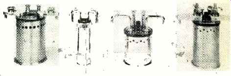
Fig. 5. Thomas standard resistor (left) is rated at 1 ohm to 0.0001 %.
Units to right are other low-resistance standards.
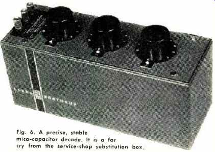
Fig. 6. A precise, stable mica-capacitor decade. It is a far cry from the
service-shop substitution box.
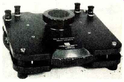
Fig. 7. Three sets of carefully wound coils interact in the Brooks "Inducto-meter" for
inductance readings on a linear scale.
In voltage calibration, it is often advisable to use a standard high enough for the high scales and employ a precise resistance divider for lower voltage scales. A "universal potentiometer" of this type, made by Leeds & Northrup of Philadelphia, Penna., is shown in Fig 3. It combines a standard voltage source with resistors and a potentiometer of exceptional precision. Voltage accuracy is rated to ±0.01% and readable output down to 0.1 microvolt is available. An instrument of this type is also useful in laboratory applications other than calibration.
A less complex resistance voltage divider is shown in Fig. 4. Designated model RD-1 by its manufacturer, North Hills Electronics, it is available for $425. Used in conjunction with an external voltage source, its output is that fraction of the input which is indicated by the numerals above each of the decade switches.
For precise resistance calibration, Thomas-type standard resistors (named after the person who developed them) are available from Leeds or Northrup.
The one shown to the left in Fig. 5 is a 1-ohm unit certified to an accuracy of 0.0001% if temperature is controlled.
Shown with it are other standard resistors with values of 1 ohm and less.
While d.c. standards and calibration methods have traditionally lent themselves to greater accuracy than is obtainable for a.c., recent developments have improved a.c. techniques considerably. Since there is no a.c. equivalent of the standard cell, most sources of a.c. voltage and current are refined, electronic signal generators. One company, for example, offers an a.c. standard at 400 cps that is accurate to ± 0.1% in frequency and = 0.025% in voltage.
Aside from voltage, one dealing with a.c. may want to check such other parameters as impedance and power factor.
Precise units of inductance and capacitance are called for. Figs. 6 and 7 show devices in this category made by Leeds Northrup. Fig. 6 is a capacitor box made up of precisely calibrated, highly stable mica capacitors mounted on high quality decade switches. Its rated accuracy is ±0.1 %, +0.5 pf. Calibrating capacitors more precise than this set, although they will seldom be required, are available.
The Brooks "Inductometer" of Fig. 7, available for $550, consists of three sets of carefully wound coils. One set is mounted in the rotating disc, which is calibrated in millihenrys. One set of fixed coils is located above the disc, another below it. When the disc is rotated, mutual-inductance changes provide the variety of inductance readings possible. The coils have been carefully designed and shaped so that rotation over 170 degrees produces an almost linear change. At 1000 cps, the "Inductometer" is accurate to ± 0.3 %.
Conclusion
The relatively crude procedures outlined for the simple v.o.m. and v.t.v.m. in the early portion of this article can be improved considerably and also made easier with some of the devices described subsequently. Also, with these more refined standards, other types of instruments and parameters can be checked. Yet, of necessity, the special devices available have only been touched on. The complex matter of frequency calibration and standards, for example, has not been treated at all. Actually it would take more than one volume to give the broad area of calibration and standards comprehensive treatment.
Nevertheless, much has been achieved if interest in the subject has been aroused. On the practical level, further information can be obtained from the National Bureau of Standards and the manufacturers mentioned in this article on the following: standards, their prices, and organizations that specialize in providing calibration service.
Another practical alternative is available for individuals or small organizations that prefer to do their own work but cannot justify the required investment. If calibration checking is not done on a steady schedule, it is possible to rent precisely calibrated equipment on a short -term basis, either for a particular job that requires exceptional accuracy or to check regular equipment. General Electric's Instrumentation Service in Schenectady, N.Y., for example, offers a long list of rental equipment. While the manufacturer's own line is, of course, fully represented, instruments from other sources are included on the list.
A Wheatstone bridge by Leeds & Northrup, to cite one example, is available for $18 a month. G-E also maintains, as do other manufacturers, an instrument repair and calibration service shop from which trained technicians are available on an outside-call basis.
Any firm interested in maintaining precision of its measuring instruments has a wide choice of alternatives that may be fitted in with its needs and its budgetary considerations.