(source: Electronics World, Aug. 1963)
By FREDERICK VAN VEEN /General Radio Company
Significant developments in the past ten years, especially those that have advanced the art of measuring. New types of test instruments that measure frequency by counting, record quantities graphically, measure L, C, R, Z, voltage, and special microwave measuring devices.
THERE has been, over the past decade, a tremendous improvement in electronic measuring instruments.
The rapid advances in precision, accuracy, and convenience of measurement have played a vital part in the electronics "boom" that has meant a 600% rise in sales dollars.
Everything, in a sense, begins with measurements, and the limits of measurement are the limits of science.
The boom in electronic measuring instruments is a mixed blessing to the average technician. Ten years ago it was pretty easy to select a bridge or voltmeter for a specific job. Shopping was a matter of looking at a few catalogues and inter-comparing some specifications. Then the measurement industry really expanded, manufacturers outdid one another in offering varieties of multipurpose instruments, and the catalogues bulged. The 1953 IRE Directory listed 69 manufacturers of bridges; the 1963 edition lists 140. Under "Graphic Recorders" the 1953 directory lists 47 companies, the current volume, 145. The 1963 edition lists no fewer than 224 companies making digital counters, a category not even included in the directory of a decade ago! The hundreds of different instruments manufactured to measure frequency, impedance, resistance, inductance, capacitance, voltage, and current represent a wide choice of accuracies, features, and price. There is also, of course, the duplication inherent in our competitive system. No one article or series of articles can do justice to the overwhelming number of direct-reading instruments available today. The emphasis here will be on the more significant developments of the past ten years, and especially those that have advanced the state of the measurement art.
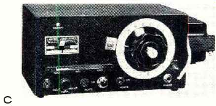
-------- Probably the most important new type of instrument of the past
decade is the frequency meter using digital counting techniques. This
example, the General Radio 1151-A, is a general-purpose counter for laboratory
or production -line use that can measure frequency accurately from a fraction
of a cps up to 300 kc. The unit also measures the period of a cycle and
frequency ratios. Price: $1195.
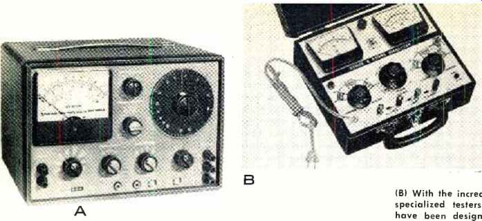
----------(A) Many direct-reading instruments are highly versatile
since they may combine several functions within a single unit. Our example
is in the audio field. The device shown, the Eico 902, combines an a.c.
v.t.v.m. for accurate audio measurements, and generators and filter circuits
for making both harmonic-distortion and inter modulation-distortion tests.
Such measurements are read directly on the meter face. Distortion figures
are within 5% of full scale and the voltage figures are ±4% of the full-scale
reading. The price is $250, factory-wired.
(B) With the increasing use of semiconductor diodes in equipment have come specialized testers for checking these components. Many of these testers have been designed for practical laboratory use as well as for incoming diode stock inspection. One typical unit, the Seco 210, includes tests for zener diodes, silicon and germanium power and signal diodes, as well as selenium rectifiers. Various variable sources of power are incorporated in the circuit. Results are displayed on two meters. Price of unit: $154.95.
(C) Not all frequency meters are digital devices. Typical of the more common
and, incidentally, less expensive type is the Lampkin 105 -B shown.
This instrument is a heterodyne-type frequency meter with a built-in crystal calibrator. It is used to measure transmitter frequencies anywhere in the range of 100 kc. to 175 mc. In addition, it will function as an accurate weak-signal generator for receiver alignment. Instrument meets FCC requirements for a frequency monitor in the mobile -radio service below 50 mc.
With some additional equipment, the meter will also meet the FCC accuracy requirements for the newer split -channel frequencies. The price is $260.
Mechanical and Convenience Improvements
The measuring instruments of 20 or 30 years ago were typically big, black, square, and heavy. This was simply the way people thought instruments should look; indestructible, reliable, conservative. But styles change and most of the black, square instruments went the way of black, square automobiles. Today's instruments enjoy the benefits of new materials, miniaturization, and much of what is sometimes called "human engineering" but which has always been a part of just good mechanical design.
Instrument cabinets now try to be all things to all people; some can be quickly adapted to relay -rack, bench, or portable use. Then there is the tiltable cabinet, with a captive cover that serves as an easel -type stand when the instrument is in use. Extensible front legs on mangy cabinets let the user look at the front panel head -on whether he is sitting or standing at the bench. And cabinets of the larger manufacturers come in standard sizes, so that they can be stacked into a neat arrangement.
Readouts have improved tremendously. The meters are larger with scales designed for easy reading. And, too, there are now digits -neon digits, incandescent digits, projected digits, digits in windows, and more digits on printed tape.
Instruments are lower--the form factor apparently follows that of automobiles. The day of the three -inch -high instrument has arrived, apparently to save relay-rack space. Instruments used in the field have become more portable than ever, as they are transistorized. Also, some instruments with heavy power demands are starting to "go portable," thanks to the rechargeable nickel-cadmium battery.
There are so many convenience improvements in instruments that it is difficult to list them all. But one that deserves special note is the quality of instruction manuals. Another is the greater availability of manufacturers' sales and service engineers. Manuals and consulting services can be just as important as some of the instrument's technical specs.
Instrument Specifications
The buyer of an electronic instrument must be guided by the specifications published by the manufacturer, but the catalogue shopper who tries to select an instrument purely by published data had better be on his toes.
Not that the manufacturers aren't truthful. Dishonest specifications are fortunately a rarity in this business, because they punish their perpetrators too quickly. But every manufacturer wants to put his best foot forward and stress the specifications where he is strongest. Also, there are many honest differences of opinion among manufacturers on just how best to state something. Take, for instance, the problem of specifying the low limit of measurement on a v.t.v.m.
Suppose the voltmeter has a low range with a full scale of 10 microvolts, and an accuracy of ± 10% of full scale. The voltmeter will certainly measure voltages below 10 microvolts, but a 1microvolt reading might be wrong by 100 %, and most people would not consider that a measurement.
Another aspect of the same problem: a 3% voltmeter is generally more accurate than a 2% voltmeter if the 3% is 3% of indicated value and the 2% is 2% of full scale. The moral of all this is that you should not play the numbers game with instrument specifications, but should read words as well.
One of the best ways to approach laboratory instrument selection is to consult the manufacturer. Sales engineers who sell such electronic instruments are, by and large, extremely competent, helpful, and low-pressure. They will try to steer you to the right choice of instrument, even if it means steering you to another company. They offer a valuable consulting service for anyone with a measurement problem, and the wise shopper takes advantage of it.
But even knowing where to start is a problem. There is a bewilderingly large number of electronic measuring instruments made by several hundred different manufacturers to measure more than 200 different electrical and electronic parameters, separately and in combination, in many different frequency ranges, and to varying degrees of accuracy and precision. You may know exactly what you want to measure and the conditions of measurement, yet there is no quick way to narrow your selection to those instruments that qualify.
Certain so-called "buyers' guides" try to classify instruments, but the task is too much for them. Several manufacturers publish excellent catalogues that bring order to their own houses. But the job of classifying all instruments in terms of well-defined standards remains.
A hopeful beginning is the recently published program of IEEE Subcommittee 25.1 on Basic Standards and Calibration Methods. As a first step, this committee has designated three echelons of accuracy level. Echelon I is the highest calibration accuracy available within a country, Echelon II an intermediate level, typically that of the calibration laboratory of an instrument manufacturer, and Echelon III a level at which measuring instruments are calibrated before use by the ultimate consumer. For each echelon, various IEEE Technical Committees will report on the measurement accuracies available and needed. In its statement of objectives, the IEEE Committee says, "An appraisal of the present status of electrical measurements points up mainly the limited availability of complete, reliable technical information." All who make, buy, or use electronic instruments will wish this particular committee Godspeed in its work.
Measurement of Frequency
Today's most popular frequency-measuring instrument the counter--scarcely existed ten years ago. Now that digital counting techniques are being widely applied to so many measurements, the frequency counter must be considered the most important new instrument of the past decade. The modern frequency counter represents a unique melding of borrowed technologies: the flip -flop circuit from atomic research, pulse techniques from radar, binary switching logic from computers. The counter became a practical instrument with the development of a method of converting binary information to decimal, new digital indicators, and improved switching devices.
The principles of counters are well known, and are here worth only passing mention: Successive cycles of the frequency to be measured are passed through a "gate" and counted, the total being indicated by a digital display. The counting time, or the time that the gate is open, is determined by a reference crystal oscillator, usually built into the counter.
If the gate is set to remain open for one second, the digit display is direct-reading in cycles per second. The unit of time is established by a crystal oscillator--usually called the "time base"--and the accuracy of this time base determines, more than any other single factor, the accuracy of frequency measurement.
If one is interested chiefly in accuracy, then the significant specification is the accuracy and stability of the time-base oscillator. The possible error corresponding to time -base inaccuracy must be added to the plus -or -minus one-count error inherent in all counters. Other errors can be caused by noise -, but these are harder to evaluate.
Frequency ranges of counters vary widely, but the upper limit for direct -reading counters is presently about 50 mc.
Heterodyne converters extend this range up to 1000 mc. with no sacrifice in accuracy, and transfer techniques are used from 1000 Inc. to above 10,000 mc.
One of the most valuable features a counter can offer is versatility -the ability to rearrange its components for different types of measurements. Thus many firms advertise "universal" counters. This usually means that the instrument can measure not only frequency, but also period, time interval, and frequency ratio as well.
To pleasure period, the functions of the "unknown" and time -base signals are interchanged, so that successive cycles of the unknown frequency open and close the gate, while "clock" pulses from the time base are counted. As a result, the digits displayed indicate the number of time units (e.g., 10 -µsec. units if the time base is a 100-kc. oscillator) passed during one cycle of the unknown frequency. At frequencies much lower than that of the time base, a period measurement will yield greater precision, due to the higher count used.
A time-interval measurement also counts "clock" pulses from the time base, but here the gate is opened by one signal and closed by another. In frequency-ratio measurement, one signal is used to open and close the gate, while the other is counted.
A consideration of increasing importance is the adaptability of the counter to accessory instruments. If you require permanent records of measurements, you will need either a data printer or the combination of digital–to-analog converter and analog recorder. Whether a particular counter will operate with a certain printer or D/A converter depends on the type of coding used, input and output voltage levels, and other considerations. Failure to check these in advance can easily lead to a pair of incompatible instruments.
Digital counters are by no means the only way to measure frequency, and it is unlikely that they will ever take over completely. For some applications, in fact, digits are a real nuisance. Suppose, for example, that you are trying to adjust a variable-frequency oscillator to exactly 12,230 kc., while monitoring the output frequency on a counter. You trim one way and then the other, as the digits dance tantalizingly around (but not on) the desired frequency. How you would long, at this point, for a heterodyne instrument with which your ears could guide you quickly to zero beat! It is a good idea to remember that any good variable -frequency reference, such as a signal generator, can be used with mixer and detector to measure frequency.
At frequencies up to about 1.5 mc., there are lab analog instruments available. One, using an interpolation technique with most of the frequency suppressed onto a switch setting, offers an over -all accuracy of ± 0.2% from 3 cps to 1.5 mc.
And instruments for coarse frequency measurements–wave-meters and grid-dip meters--still enjoy a brisk market.
There is every reason to expect further substantial improvements in frequency measurements. Accuracy is, as mentioned, largely a function of the accuracy or stability of the frequency reference. Thus, it is possible to increase the accuracy of any counter by the use of a highly accurate frequency standard as the time base.
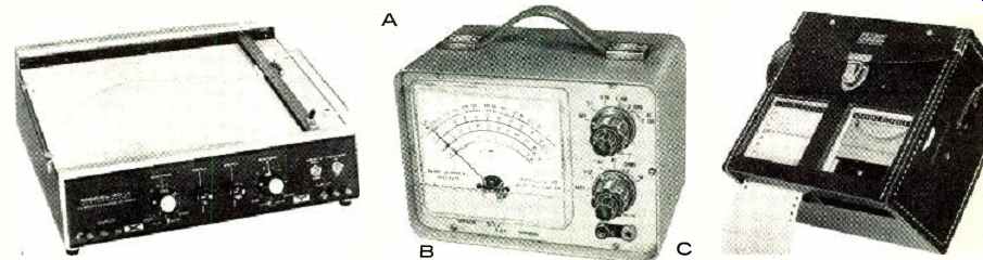
------ (A) Graphic recorders are widely used in industry where a written
chart showing one or more variable functions is required. The recorder
shown, a Moseley 2D-4, draws rectangular coordinate curves from two related
sources of d.c. electrical information on standard graph paper. Writing
area is 10 x 15 inches. High -gain solid -state servo amplifiers drive the
two motors that are coupled to balance pots and recording pen. Ten calibrated
input ranges from 0.5 mv. /div. to 10 v. /div. may be selected from the
front panel of the recorder. The liquid-ink pen has a maximum writing speed
of 15 inches per second. Price is $1490.
(B) Even vacuum-tube voltmeters have become transistorized. DeVry transistorized meter combines advantages of a v.t.v.m. with those of a sensitive microammeter for service -bench use. Instrument is completely portable, operating on four flashlight batteries. It has usual a.c., d.c., and resistance ranges, along with four d.c. current ranges from 50 ua. to 50 ma. full-scale. D.c. input impedance is 10 meg on most ranges. The price of the voltmeter is $89.50 ready -wired or $64.50 in kit form.
(C) Graphic recorders need not be large and bulky as shown by the Amprobe ATM -2. This is actually two most -frequently used recorders in a single compact carrying case. One of the units is an expanded range a.c. voltmeter and the other is a high -current a.c. ammeter. Roll of 21/2" wide pressure -sensitive paper, traveling at 12" per hour carries the record of voltage and current. With the paper removed, pointer position is visible on a calibrated scale so that unit can be used as an indicating meter. Price of the 2recorder unit and case is $181.20.
Measurement of Capacitance & Inductance
Capacitance and inductance measurements involve similar techniques and limitations. The basic instrument for precision measurements is the bridge--an instrument that permits the adjustment of a calibrated known until a state of electrical balance exists between it and the unknown. Here, as in frequency measurements, the major burden is on the accuracy of the "calibrated known," or standard. But even the best standard is of little practical use in measurements unless its accuracy can be somehow extended over a wide range of values. One significant advance in bridges over the past few years is the transformer ratio -arm bridge, a device for extending the usefulness of a single standard over a range from 1 /1000 to 1000 times its value or better, with no sacrifice in accuracy. Although the transformer bridge was originally conceived over 30 years ago, its principles have only recently been exploited in commercial instruments. The most accurate capacitance bridges available use ratio arms to achieve direct reading accuracy of 0.01% over a wide range of capacitance.
Capacitance standards can be made more accurate than inductance standards. The capacitance bridges just mentioned use ±0.005% standard capacitors, for example, whereas the best standard inductors are ±0.1% units. Inductance bridges therefore use capacitors, rather than inductors, as standard reactances. The most accurate inductance bridges available offer ± 0.1% direct -reading accuracy.
The ultimate accuracy of most precision bridges is, incidentally, well beyond the direct-reading accuracy. A high degree of resolution, that is, a readout of five, six, or more significant figures, can be used for ultraprecise inter-comparisons. One of the 0.1% capacitance bridges, for example, permits inter-comparison of capacitors to within one part per million.
Capacitors and inductors can be measured in terms of either series or parallel equivalent circuits, and many bridges therefore offer switch selection of C,, Cn, Ls, and Lr. The difference between Ls and L and between C. and Cr is less than 1% for inductors with "Vs" over 10 and for capacitors whose dissipation factor is less than 0.1.

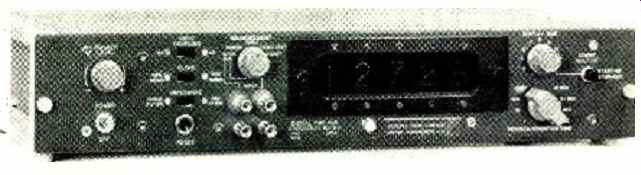
----- (A) Another example of an electronic counter is the Hewlett-Packard
52141.. This instrument totalizes and measures frequency and period.
In addition, it can directly display readings in practical units, such as
gallons /sec. or ft. /min. from appropriate transducers. Two sets of decades
are used: one to register the signal being counted; the other may be preset
to any number from 1 to 100,000 to control a gate circuit that may be used
to operate other equipment. Unit can be used to monitor automated processes,
and for production testing and for laboratory applications. The price of
the electronic counter is $1475.
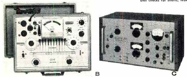
(B) There is still much equipment in use that employs vacuum tubes. To
check the performance of these tubes on the service bench requires an
easy-to-use, flexible tube tester, such as the Triplett 3414 shown. This
unit checks for shorts, leakage, and plate conductance. A self-contained
roll chart supplies test setup data. Sockets are provided for octal, loctal,
and miniature tube types. The price of the tester is $109.50.
(C) An example of direct -reading, accurate capacitance bridge that can measure very small capacitance values is the Boonton Electronics 75B shown. The instrument was originally designed for use in measuring the temperature coefficient of small "zero temperature coefficient" ceramic capacitors. It is also used for capacitance measurements of semiconductors at millivolt levels. Lowest range of the bridge is the extremely small value of only 0.1 pf. full-scale. Values as high as 1000 pf. can be measured with this particular capacitance bridge. Price: $1375.
Resistance Measurements
The instruments most often used to measure resistance are the ohmmeters included with many voltmeters. The accuracy of such an ohmmeter is limited to 5 or 10 %, partly because of trying to squeeze an infinite range into a finite scale.
The resistance bridge is easily able to achieve 0.1% accuracy up to 10 megohms or so. Measurements of very high resistance are made by megohm bridges, which supply the required high voltages. One megohm bridge will measure resistances up to 10^15 ohms, with 1% accuracy up to 10^15. Resistance limit bridges are direct-reading in percent deviation rather than in ohms. Such bridges are used by production-line personnel to determine quickly whether a component is within specified tolerance.
The exceptional accuracy of frequency standards has been applied to the measurement and standardization of other quantities. The ohm has thus been defined in terms of frequency and length, and standard resistors can now be specified in terms of a few parts per million. Standard resistors are used in series and parallel combinations, linear voltage dividers, and conventional bridges to extend their usefulness over a wide-range of measurement. Present state-of-the-art for general-purpose, wide -range resistance bridges seems to be the same as for capacitance: ±0.01 %. The most popular bridges are those that measure resistance, capacitance, and inductance--the so-called "universal" bridges. This popularity is easy to understand when, in this day of four and five -figure prices, less than $500 can buy a self-contained, battery-operated, portable, five bridges–in-one instrument that measures C, R, and L to ± 1 %, and also measures dissipation factor and "Q."
Voltage Measurement
The digital revolution came to voltmeters less than ten years ago, and digital voltmeters are now produced by many manufacturers. The extra precision afforded by digital readout is of especial advantage in d.c. measurements, where the attainable accuracy warrants such fine resolution. Digital voltmeters are considerably more expensive than the usual analog meters of comparable ranges and quality, and this relation is likely to continue. Another relation that seems basic is that between the accuracies attainable in a.c. and d.c. measurements. While d.c. voltage can be measured to about ±0.002 %, the best a.c. measurements are at least an order of magnitude less accurate. The a.c. voltage is usually measured in terms of a d.c. equivalent, and the translation from one to the other has to cost accuracy.
The scales on almost all a.c. voltmeters are calibrated in terms of r.m.s. voltage. However, until a year or two ago, most voltmeters actually responded to either peak or average value, with the scale conversion in terms of r.m.s. voltage assuming sine -wave input. Now “true r.m.s." voltmeters have begun to appear in quantity. The most common type of true r.m.s. voltmeter measures a.c. voltage in terms of its heating effect on a thermocouple. This effect is compared with the heating effect produced by a reference voltage. Other true r.m.s. meters use dynamometers and rectifiers whose non linearities synthesize r.m.s. response. True r.m.s. response cannot be maintained by these means for all input waveforms, and the specification "maximum crest factor," that is, the maximum ratio of peak to r.m.s. voltage for which the voltmeter is reliable, is especially significant in pulse work.
The peak- and average-responding voltmeters are highly refined from years of development, and will probably continue to enjoy considerable popularity based on their price advantage.
Most peak instruments rectify the input voltage and then amplify the d.c. Their chief advantage is good high -frequency response. Also, since they include a d.c. amplifier, they can be made to measure both a.c. and d.c. voltage quite easily.
A disadvantage at low voltages is that the a.c. output no longer bears a linear relation to the a.c. input.
The typical average-responding voltmeter first amplifies the input signal, then rectifies it. A wide -band amplifier, stabilized by negative feedback, is generally used. Although its high-frequency limit is well below that of the peak-responding voltmeter, it can measure much smaller voltages.
At very high frequencies, broadband amplifiers are difficult to design. At low voltage levels, rectifiers assume complicated characteristics. Therefore, the measurement of high frequency, low-level voltages poses a special problem. One method of solving it is to accept the complex rectifier behavior and compensate for it on the meter scale. Another is to use a matched pair of semiconductor rectifiers, one to rectify the input voltage, the other to rectify a low-frequency reference voltage, and to compare the d.c. outputs. Commercial instruments of both types are available.
The measurement of very small d.c. voltages is best accomplished by an electrometer. Some electrometers convert the small d.c. voltage to an a.c. voltage that is amplified and metered, while others use direct -coupled amplifiers. A good electrometer can measure d.c. voltages down to a few microvolts or less and currents to below 100 femto-amperes ( a femto-ampere is equivalent to 10^-15 ampere) .
Wave Analyzers & Graphic Recorders
Many voltmeters travel under other names, because they are only indirectly concerned with mere measurement of voltage. An example is the frequency-selective voltmeter known as a wave analyzer. Operating ahead of the voltmeter in a wave analyzer is a filter that passes only a certain frequency band. The bandwidth is a constant number of cycles in some analyzers, a constant percentage of center frequency in others. The constant -cps bandwidth is generally more useful except at very low frequencies or where a logarithmic plot is required. Optimum bandwidth depends on how much detail you need. Very narrow bandwidths give more data but require more time for analysis. Wider bandwidths offer greater convenience at the cost of some detail. A wave analyzer with switch selection of two or three bandwidths lets you have your cake and eat it, too.
Of course, the chief application for wave analyzers is waveform measurement, and thus the oscilloscope and graphic recorder are important accessories.
The combination of a wave analyzer and an oscilloscope or recorder is known as a spectrum analyzer. Spectrum analyzers are available from very low frequencies to at least 100,000 mc. Most use automatic frequency sweeping to give continuous oscilloscope display. The modern spectrum analyzer combines the features of the wave analyzer, oscilloscope, and sweep generator in a sophisticated system extremely useful not only in electrical waveform measurements, but, with transducers, in studies of sound, vibration, heartbeats, and analogous phenomena.
The graphic level recorder is another type of voltmeter. A pen marks the voltage level on a piece of graph paper.
Then, as the paper is moved under the pen, with the motion of the paper corresponding to changing time or frequency, the pen continues to plot the voltage level. The result is a response plot of the input voltage vs frequency or time.
The graphic recorder is widely used for spectrum analysis. Although it can't keep up with the sweeping rates of an oscilloscope, it has its own advantages, principally the permanence and greater resolution of its record.
Graphic level recorders measure a.c. or d.c. voltages. There is a wide variety of chart speeds, writing speeds, and voltage and frequency ranges. Some write with ink, some electrically. When the recorder is used with a variable-frequency source, a primary consideration is the means for transferring the frequency scale onto the chart paper. Some means of linking the oscillator frequency dial to the recorder drive mechanism must be provided, as well as chart paper especially calibrated for the setup.
Microwave Measurements
At microwave frequencies, where circuit dimensions approach wavelength, measurement techniques often differ from those at lower frequencies. The importance of physical dimensions makes partners of the development engineer and the machinist, especially at the higher microwave frequencies ... where waveguide is employed to replace coaxial line.
Power Measurement. Voltage and current vary widely along a transmission line at microwave frequencies, and power becomes a fundamental quantitative measurement. In microwave power meters, the power is converted into heat and measured either in terms of temperature rise or of resistance change in a bolometer. The first type the calorimetric power meter--is generally used for measurements above 10 watts, while bolo-meters are limited to lower levels.
Frequency Measurement. The effects of physical dimensions at microwave frequencies are used to advantage in several instruments unique to the microwave part of the spectrum. The cavity type frequency meter is the microwave version of lower-frequency tuned-circuit wave-meters. The cavity is a simple wave guide or coaxial section that can be sharply tuned to resonance. The signal to be measured is coupled to the cavity, the cavity adjusted, and the resonant point noted on a finely calibrated scale.
The mechanical nature of such a device limits accuracy to about x-0.01 %; for higher-accuracy measurements, multipliers, mixers, and transfer devices are added to lower-frequency precision instruments.
V.S.W.R. and Impedance Measurement. Another important instrument peculiar to the microwave region is the slotted line. The slotted line is a section of coaxial line or waveguide that is slotted, with a movable probe sampling the field in the line. The slotted line can hardly be considered a direct-reading instrument; like the cavity frequency meter, it is simply a device for "coupling into" a transmission line to sample the standing -wave pattern. But whereas the cavity includes a calibrated frequency scale, the results of the slotted -line measurement ( v.s.w.r., impedance, and associated parameters) are usually taken off a Smith Chart, slide rule, or auxiliary detector.
The admittance meter and reflectometer are alternate instruments for the measurement of impedance, v.s.w.r., etc. The admittance meter uses a bridge technique, in which pickup loops in the bridge arms are oriented to balance the unknown admittance against conductance and susceptance standards. The reflectometer is basically a power meter used to measure the ratio of incident to reflected power, or reflection coefficient.
There have been few changes in the fundamentals of microwave measurement over the past decade. Of course, the frequency range of interest is always expanding, and the instrument developer must keep pace. But the old bolo meter and calorimeter still reign supreme in power measurements, even though they are now associated with the greater convenience of self-balancing bridges.
There is constant improvement in measurement accuracy throughout the spectrum, but one cannot expect the same accuracies at microwave frequencies as at 100 kc. Once you have entered the gigacycle area (1 gigacycle = 1000 mc.), you no longer talk about parts per million, and are very happy to measure within parts per thousand. A tenth of a percent is a very decent accuracy for a cavity frequency meter at 15 gc., and commercial microwave power meters are typically in the 3 to 5% class.
REFERENCES
1. "A Program to Provide Information on the Accuracy of Electrical Measurements," Proceedings of the IEEE, Vol. 51, No. 4, April 1963.
2. McAleer, H.T.: "Digits Can Lie," General Radio Experimenter, Vol. 36, No 12. December 1962.