(source: Electronics World, Aug. 1963)

By HOWARD L. ROBERTS / Hewlett-Packard Co.
Devices used to generate test signals from below the audio range up through microwaves. Performance, specifications, and effect of semiconductors on equipment design are covered.
SIGNAL-generating equipment comprises a wide variety of electronic instruments for generating test signals.
This class of instruments includes everything from the human finger, placed on a grid connection, to complicated check-out equipment which automatically generates a number of frequencies, voltages, and other signals for quickly testing intricate missile systems.
The finger test may be all that you need if you merely want an indication of whether the equipment is working or not. But when you need to know how well the equipment works, then the appropriate piece of signal-generating equipment must be called upon to provide the answer.
If, for instance, you want to measure distortion in an audio amplifier, you need an oscillator that generates sine waves with far less distortion than you expect the amplifier to have.
If you want to measure the rise time of a switching circuit, you ought to have a pulse generator that produces pulses with rise times faster than the switching circuit.
Types of Equipment
Signal-generating devices may be loosely grouped into two categories: special-purpose and general-purpose generators.
Special-purpose generators are designed for specific kinds of tests and usually generate only those combinations of frequencies needed to test certain kinds of equipment. An example of this type is an FM stereo test generator. Special-purpose generators are best suited for making repetitive measurements since their built-in features make specific tests faster.
General-purpose equipment may not have many combinations of signals but usually can generate signals over broader ranges of frequency and amplitude. These generators find most use in the experimental and development laboratory, both professional and hobbyist, but are often used for specific tests as well. Presumably, any test performed by a special purpose generator can be performed by an assortment of general-purpose equipment, but several instruments may be required to do the same job.
Since the basic design principles involved in general-purpose laboratory instruments are also used in special-purpose generators, we'll confine this discussion to general-purpose instruments.
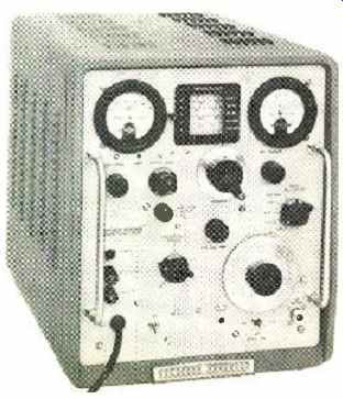
--- When an accurate, stable v.h.f. signal source is required for receiver
or v.h.f. amplifier measurements, then a standard signal generator is
required. Our example is the Hewlett -Packard 608D. The instrument is especially
suited for precise tests of narrow -band v.h.f. aircraft communications
equipment.
It has a calibrated output of 0.1 ¡iv. to 0.5 v. throughout the 10 to 420 -mc. band. Output frequency can be set to within a few kc. with built -in crystal calibrator. Price: $1300.
Signal-generating equipment is often grouped according to the shape of the output signal waveform. Sine-wave generators form one important category since the sine wave is the most fundamental waveform. These instruments are widely used to test equipment performance at discrete frequencies.
Oscillators and Signal Generators
Among sine-wave generating equipment, a distinction is made between oscillators and signal generators. A signal generator is an oscillator that has accurately known amounts of output power as well as known frequencies. In many cases, this means simply that a signal generator has a meter to show the power generated by the output stage, and a precision attenuator for cutting down the indicated power by known amounts.
At audio frequencies it is a simple enough matter to read oscillator output with a lab voltmeter. For this reason, output meters are not included in the majority of audio oscillators. At r.f. frequencies, though, voltage measurements are more complex so that r.f. generators include a built -in output meter designed especially for each generator. (An r.f. generator without a meter is known as a "signal source.") RC oscillators have dominated the audio and neighboring ranges for more than twenty years. This range extends from subsonic through ultrasonic and into the low-frequency r.f. ranges.
RC oscillators are so named because their frequency-determining networks consist only of resistance and capacitance--no inductance whatever. The reason for using an RC circuit is that if an LC circuit were used, the large inductors required for low-frequency oscillations would be much too cumbersome. The RC oscillator is much lighter, easier to build, and, as it turns out, a good source of distortion -free sine waves.
These oscillators generally use some form of amplitude limiting other than driving a tube to cut-off and /or saturation.
The most common form of amplitude control is the use of a small incandescent lamp as a non -linear resistance in one of the feedback loops. The lamp's resistance changes, if the oscillation amplitude changes, readjusting the amount of feedback to counteract the change in amplitude. This type of limiting prevents the tubes (or transistors) from being driven beyond their linear operating regions and accounts for the low distortion output of these oscillators.
The oscillator circuit may also be followed by a tuned amplifier -filter ganged to the tuning dial so as to track the oscillator tuning. Filtering attenuates what little harmonic content there may be in the oscillator signal, resulting in hyper-pure sinewave output. This type of instrument is most useful for making distortion measurements on other types of equipment.
Multivibrators with very long time constants are used in instruments for the very low frequencies, some of these operating as low as 0.001 cps ( about 1 cycle per 15 minutes!) . Multivibrators generate square waves, of course, but the square waves are changed to sine waves by waveshaping networks. This is just opposite to the audio -range sine /square wave generators which start with sine waves and form these into square waves with clipping or triggering circuits.
Above 1 mc., the usual RC oscillator runs into certain problems. The tuning capacitors are in a range of values comparable to distributed circuit capacitance which makes tuning less precise. Phase-shift oscillators, a different form of the RC oscillator, swamp out the stray capacitances and can be used up to 10 mc. and beyond.
Beat -frequency oscillators are also used throughout the low frequency region. These instruments use two r.f. oscillators, one generating a fixed frequency and the other being tunable.
The outputs of these oscillators are mixed and the difference frequency is separated from the mixture by filter circuits.
The advantage of the beat -frequency oscillator is that very wide frequency ranges can be covered by a single sweep of the tuning dial, at the expense of tuning resolution however. The disadvantage is that the oscillators must be made many times more stable than the desired stability of the output signal because of the large step -down in frequency. High quality beat -frequency oscillators made for laboratory applications do achieve the desired stability, however.
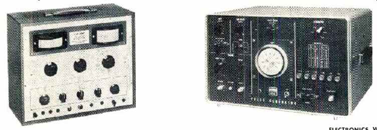
------ Designed mainly for servicing AM, FM, and TV receivers is the
Hickok 288AX sweep and marker generator. The instrument has 8 bands of
unmodulated or AM signal output from 35 kc. to 110 mc. as well as frequency-modulated
output up to 160 mc. A built-in audio oscillator, tunable from 20 to
15,000 cps, is used for modulation or for audio tests. A crystal calibrator,
with a choice of 100or 1000 -kc. signals, is also provided along with a
3-range decibel meter. Price of this unit: $315. [right] An example of
a versatile pulse generator is the Fairchild DuMont 404-B. This device can
generate pulses suitable for use in signal-sampling techniques in conjunction
with oscilloscopes. Another application is to trigger scope sweeps at the
proper time to view the leading edges of very short transients. Pulses can
be generated with widths continuously variable from 0.05 to 105 psec., with
various delays, and with repetition rates up to 250,000 p.p.s. Generator price:
$760.
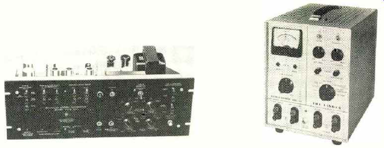
----- [LEFT] A multiplex stereo generator developed for design and production
testing of FM multiplex adapters, tuners, and receivers is the Scott
830. The unit has also been used by FM broadcast stations to produce a
composite stereo signal. When feeding a composite stereo signal into the
front end of a tuner, the generator's output is used to modulate a laboratory-quality
standard FM signal generator. The price of the unit: $600. [RIGHT] Intended
mainly for the service technician working on FM multiplex equipment is
the Fisher Model 300 multiplex signal generator. The instrument is also
suitable for use in production testing. Incorporated are an audio oscillator
and an r.f. generator, which is factory tuned to the approximate center
of the standard FM broadcast band. An output level indicator is also provided.
Price of generator: $495.
R.F. Signal Generators
The designation "r.f." is another all-embracing term, originally referring to signals that were destined to be radiated or detected as radio waves. As it turns out, radio signals are now propagated at frequencies even lower than 20 kc. ( standard frequency broadcasts such as WWVL) and at super high frequencies measured in thousands of megacycles ( giga-cycles ) . Our discussion here will be confined mainly to those radio-frequency generators which have lumped LC circuits, using coils and capacitors in the resonant circuit.
During the forty-odd years that these generators have been used, they have undergone considerable refinement. Factors which upset frequency stability have been designed out of the circuits. Manufacturers have learned how to wind coils tightly of low expansion wire on matched ceramic forms so that there is little change of inductance with a change in temperature. In high-quality generators, capacitors are made from rigid precision -machined plates, which are silver- or gold-plated for minimum resistance to r.f. surface currents (skin effect). In recent years negative feedback has been used in various ways to improve amplitude stability and modulation characteristics.
Even with all these refinements, a good r.f. signal generator still includes an accurate crystal-controlled frequency calibrator to enable precise setting of frequency. The calibrator frequency is usually a whole number, such as 1 mc., so that it is easy to spot the harmonics.
Such r.f. generators also include amplitude or frequency modulation capabilities. This enables the generator to supply signals which resemble the actual signals to be used by the equipment being tested.
When the response of a sharp cut-off filter or i.f. circuit is being measured, modulation may wobble the r.f. frequency across the circuit's cut-off point, broadening the apparent response curve. For this reason, most r.f. generators use the master oscillator-power amplifier (MOPA) configuration which isolates the oscillator from the output amplifier, permitting amplitude modulation of the amplifier without affecting the frequency of the oscillator.
The output impedance of r.f. generators deserves special comment. If the output cable and load impedances aren't the same, r.f. energy reflects from the load, giving rise to standing waves. If the generator itself is not matched to the output cable, then reflections are re-reflected, which alters the character of the standing wave and interferes with measurement accuracy. Most r.f. generators are matched to one of the 50, 75, or 300-ohm impedance levels commonly used but pads or baluns are required to match other impedances.
Because of standing waves, the r.f. voltage at the generator may be different from the load voltage. For this reason, an output voltmeter is a reliable indicator of signal strength only when the load is matched to the generator.
The attenuators of r.f. generators require careful design to account for distributed capacitance and inductance. These devices are frequency -sensitive unless components are positioned carefully. Furthermore, the impedance of the attenuator must be matched to the output cable at all settings.
U.H.F. and Higher Frequencies
Above .300 mc. the inductance and capacitance of tuned circuits become so small that it is difficult to treat them as discrete circuit elements. At these higher frequencies, resonant cavities Of one sort or another are generally used as the resonating elements.
Gridded tubes for u.h.f. frequencies have rather odd shapes so that all elements make contact at the right place when installed in a cavity. Above 1000 mc., klystrons are most often used as oscillators.
Microwave signal generators use a single power oscillator for the r.f. channel, avoiding the cost and complexity of a power output stage. Because of this, modulation is usually restricted to pulses and square waves. Modulating waveforms turn the power oscillator completely off and on, making the transition between off and on states as fast as possible to minimize frequency pulling or FM as the klystron voltage changes. On the other hand, it is relatively easy to frequency modulate a klystron over a range of a few megacycles by applying a saw-tooth voltage to the klystron repeller.
The attenuators of these generators also avoid the use of lumped circuit elements, the waveguide-beyond-cut-off type being favored. This attenuator uses a pickup loop which slides in and out of a length of waveguide that opens into the resonant cavity. The waveguide dimensions are smaller than those required to carry an electromagnetic wave at the frequency of the oscillator but the cavity's magnetic field leaks into the waveguide. The further the loop is from the cavity end, the weaker the field is and, what is more, the field strength drops off in a predictable manner so that these attenuators are inherently accurate.
Sweep Generators
Sweep generators are indispensable for anyone concerned with circuit response throughout a band of frequencies. A straightforward way of obtaining a sweep frequency is to add a motor drive to the oscillator tuning dial. This approach is widely used at audio and low frequencies, where electronic techniques for changing frequency fail to achieve the necessary wide (in terms of number of octaves) bandwidth. The beat -frequency oscillator shines here as a means of getting wide sweeps.
Motor drives are also used at radio frequencies but vibrating capacitors often serve to vary the oscillator frequency.
At microwave frequencies, the voltage -tuned backward -wave oscillator (b.w.o.) can easily sweep through an octave band of frequencies simply by modulating the helix voltage.
Motor-driven sweeps, unless carefully designed, cause mechanical vibrations which induce microphonics that generate spurious oscillations. Motor -driven sweeps are also limited in speed. Electronic sweeps, which vary the oscillator tank circuit's resonant frequency either with a reactance tube, a voltage-variable capacitor, or a saturable reactor, are used wherever possible.
Many service-shop sweep generators have a fixed sweep rate of 60 cps, taken right from the power line. This simplifies circuitry and also makes synchronization of related oscilloscopes easier.
Circuit response is usually displayed on an oscilloscope.
The sweep rate should be fast enough to obtain a flickerless display. Slow sweep rates are required for pen recorders which may trace with more detail than a scope does.
Pulse and Square-Wave Generators
Pulse and square-wave generators produce signals of an "off-on" nature by switching between two d.c. levels. These generators are used to check systems which operate in a pulsed mode, such as radar modulators, oscilloscope triggering circuits, computer circuits, and teletypewriter systems.
These generators are also used for transient response testing of linear systems.
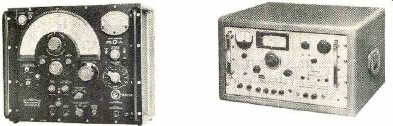
---------- In order to take quantitative r.f. frequency response measurements,
a sweep frequency generator is used. The response curve, traced on a
scope, is usually marked with a marker generator. Incorporating both
functions in a laboratory instrument is the General Radio 1025 -A. The
unit covers 0.7 to 230 mc. plus two bandspread ranges (400 - 500 kc.,
10.4 - 11 mc.) for i.f. curves. The accurate marker pip is continuously
adjustable in frequency and amplitude. Price: $3250. [RIGHT] Another
example of sweep frequency generator is the Jerrold Model 900 -B. This instrument,
which has been designed for laboratory or production use, generates sweep
signals with center frequencies from 500 kc. up to 1200 mc. in the u.h.f.
range. Sweep widths vary from a narrow 10 kc. to a wide 400 mc. for the
higher frequencies. The unit also has built-in crystal-controlled harmonic
markers and provision for external variable marker signal generator.
Price of unit: $1980.
The shape of the input pulse or square wave has to be neatly rectangular if anything is to be learned from the shape of the output pulse. Rounding of the pulse corners, or overshoot, wiggles, and sag of the pulse top, are the symptoms of system performance so should not be present on the input pulse that is produced by the pulse generator employed.
A square -wave generator is really a pulse generator having equal "on" and "off" times. "On" time duration therefore varies with frequency. Pulse generators have one control for frequency, or pulse repetition rate, and a separate control for "on" time duration, or pulse width. "On" time is usually much shorter than "off" time so that pulse generators are often used to drive r.f. oscillators or other circuits where high power is needed during the pulse but where average power should be kept low.
These generators usually use some form of multivibrator circuitry for wave generation with clipping circuits and other devices for "squaring up" the waveform. An exception is the mercury -wetted relay which, unlike ordinary relays that have a certain amount of contact bounce, latch on for good when contact is made. Generators using these relays are able to generate high power pulses with turn -on times (rise times) measured in fractions of a nanosecond (10-° second) but their use is limited because of relatively slow repetition rates.
Noise Generators
Measuring signal-to-noise ratios in receivers with sine waves or other coherent signals is complicated because of theoretical considerations involving bandwidth and noise power per cycle bandwidth. This difficulty is circumvented by using broadband noise from a suitable generator as the test signal. A comparison of receiver noise output without signal input to noise output with a known amount of noise power at the input, provides a measure of receiver performance.
Noise generators are also used as a source of broadband signals. Since "white" noise is an equal mixture of all frequencies, a test using a noise voltage as the input is a test which covers the complete range of a system all at once. This is a good one to use for spotting any resonances in audio systems or in acoustic measurements.
Broadband noise sources require careful design; otherwise, resonances may prevent an equal -energy distribution for all frequencies. Noise sources include hot resistors, gas tubes, and temperature limited diodes (these are diodes operated with low filament voltages and with plate voltages high enough to maximize shot noise in the diode current). Impact of Semiconductors
Transistors are used in signal generating equipment where their low power drain and low heat can contribute to a lightweight, battery -powered design. As the cost of transistor circuitry becomes more competitive with vacuum tubes, we can expect to see more use made of transistors in test equipment.
Low-capacitance semiconductor diodes can be used at much higher frequencies than thermionic diodes and are used as harmonic generators to double the frequency of microwave generators. They do this by partial rectification which distorts the r.f. wave, creating harmonic frequencies.
Tunnel diodes find application as low-level, low impedance r.f. generators and as fast -rise pulse generators. One available pulse generator uses a simple tunnel diode circuit to generate pulses with rise times of less than 0.1 nanosecond. Pulse amplitude, though, is less than half a volt.
The step-recovery or snap-off diode represents a recent discovery which is being designed into fast-pulse generators.
Any semiconductor diode stores a charge, when forward biased, which flows as reverse current for a brief interval when a reverse bias is suddenly applied. The step-recovery diode is designed so that this stored charge is used up abruptly, making the transition from short-circuit ( charge carriers flowing) to high impedance (no charge carriers) in less than a nanosecond. This device is used in a new pulse generator as a pulse sharpener to square up the output pulses.
Still another kind of diode is revolutionizing the modulator in microwave generators. This device, known as a p-i-n diode because of the intrinsic (no impurities or doping)
silicon layer sandwiched between the p and n layers, also exploits charge carrier flow. At microwave frequencies, a half-cycle does not last long enough for the charge carriers to be swept out, so that current flows through the diode in alternate directions in response to the r.f. voltage waveforms.
The diode appears resistive, however, and the apparent resistance is changed by varying the diode bias.
A voltage -controlled attenuator is made by placing p-i-n diodes across a transmission line so that they bypass or absorb some of the r.f. energy, the amount that is bypassed being controlled by the diode bias. The oscillator can then operate continuously and modulation is achieved by absorbing various amounts of r.f. energy without causing reflections on the transmission line.
With these diodes, it is now possible to amplitude modulate a klystron output with sine waves, or any kind of complex wave for that matter. What is more, the microwave power can be turned on and off more quickly with these attenuators than power can be built up or damped out in high -"Q" cavities.
Equipment Accuracy
A quality r.f. signal generator built during the past ten or fifteen years can be expected to have about a 1% or 2% accuracy in frequency setting.
Crystal-controlled calibrators provide a 100 times improvement at frequencies corresponding to harmonics of the calibrator. This accuracy does not hold at other frequencies, though, simply because the tuning dials of the instruments cannot be read with that kind of precision.
However, frequency can be monitored with an electronic counter to a far higher degree of accuracy. With the aid of a precision transfer oscillator and heterodyning techniques, counters can determine frequencies as high as 18,000 mc. /sec. (and higher) to an accuracy of 8 decimal places.
If an oscillator can be voltage controlled, phase -locking techniques can be used to maintain the output frequency at the same stability as a reference crystal oscillator. This can be done, though, only at spot frequencies corresponding to harmonics of the crystal oscillator frequency.
Precisely known signal frequencies are available from frequency synthesizers, which obtain various r.f. frequencies by dividing, multiplying, adding, and subtracting other frequencies derived from crystal -controlled oscillators. The newest signal source of this type generates frequencies all the way from 0.01 cps to 50 mc. in , 0.01-cps steps by push-button control. All of these 5 billion discrete frequencies are derived from one highly precise 1-mc. crystal oscillator and all are accurate to better than 0.0000003%! This is three ten-millionths of one percent.
The accuracy of signal generator output amplitude indications can't approach accuracies such as those available for frequency -primarily because highly precise standards of r.f. power never existed until only recently. High-quality generators have had output accuracies in the neighborhood of 1 to 2 db. Now that more accurate r.f, power monitors are becoming available, the trend is towards the use of power leveling for signal generator output amplitude control. In these systems, the power monitor maintains constant output power by means of a wide -band, direct -coupled feedback loop which controls an amplifier control grid, or one of the new electrically controlled p-i-n diode modulator/ attenuator units. Output power flatness can be held to within 0.2 db with this technique. The accuracy of the power monitoring system is typically ± 0.5 db overall, however an additional ± 1 db should be added because of attenuator accuracy throughout the frequency range of the equipment.
Little effort has been expended on controlling the accuracy of pulse generators with respect to pulse width and amplitude; the major design effort being directed towards achieving good pulse shape. Pulse generator calibrations are used for no more than a rough initial indication of pulse amplitude, width, or repetition rate. Because pulse generators are most often used with an oscilloscope, the pulse generator controls are usually adjusted exactly while monitoring on the oscilloscope.
Choosing Equipment
The first thing to do is to take a good, hard look at what the equipment is intended to do. What frequency ranges are needed and which can be omitted? What kind of signals are desired -sine wave, pulsed, FM, AM, or what? What stability does the generator have? That is to say, if you set it at one frequency how confident can you feel that the generator will stay exactly at that frequency? What is the amplitude stability? If you set the output for 1 volt r.m.s., will it stay at the exact 1-volt setting all afternoon, or if you change frequency? A design engineer is very much concerned with these matters. When designing an i.f. strip, for instance, he needs a generator with an output that is flat across the band, so that the detected response will show him where the i.f. strip isn't flat. The serviceman repairing the same strip can get by with a generator of lesser quality. About all that he can do is to set the traps to the right frequencies, get about the right slope to the band edges, and take excessive tilt off the passband. A few humps in the generator output won't affect these adjustments significantly.
Check the performance of the attenuators, which are needed to prevent overdriving high -gain equipment. Is the attenuator accurate, and is its attenuation constant with frequency? And watch out for r.f. leakage. A big attenuation factor doesn't tell you anything if r.f. power leaks into the tested circuit anyway.
How much harmonic content is present if you are supposed to be getting pure sine -wave output? If there are harmonics, you may think that a filter circuit is passing a certain frequency when it is really passing a harmonic. With r.f. generators, the standing wave of a harmonic may be much higher than the fundamental, providing a false indication.
Certainly, the reputation of a manufacturer is of considerable importance.
Reputable manufacturers check the performance of many production units and then set specifications beyond the widest deviations. Sometimes their specifications may not appear spectacular, but with this kind of equipment performance will always be better than claimed.