(source: Electronics World, Dec. 1963)
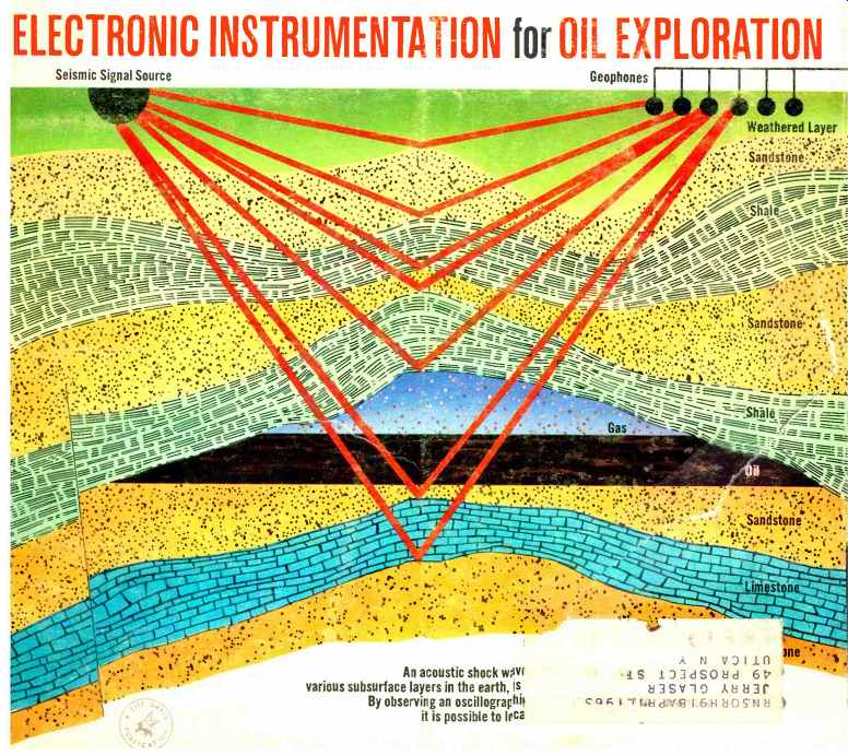
OUR COVER illustrates the subsurface layers in a cross-section of earth
that is typical of the structure found with an oil deposit. Note how the
oil is trapped in the anticline structure, which is an up-fold, bend or
arch in the rock strata.
Acoustic shock waves are reflected from the various sub-surfaces, are picked up by a number of microphone -- like transducers (geo-phones), and their signals are passed through electronic circuits to a recording oscillograph or special tape recorder. For details on this important technique for finding oil, see our lead story below (Illustration by Otto E. Markevics.) ...
By LOUIS E. FRENZEL, Jr. / McCollum Laboratories, Inc.
Geophysical prospecting using electronics has led to many oil discoveries. Acoustic sounding is now done with transistorized equipment, oscillographs, and computers.
ALL of the major fields of science and technology have profited greatly by the use of electronic techniques over the past years. Persons in the fields of chemistry, physics, biology, medicine, and engineering are beginning to realize the great potentials that electronic techniques offer. Electronic instrumentation, when used, improves existing conditions in addition to offering new avenues of approach unheard of before the use of electronics.
One field that has "discovered" electronics is geophysics.
Geophysics is the science and study of the earth and its various phenomena. Years ago, this was the only definition of geophysics, but today, because of advances in sciences like electronics, geophysics is now the study of our solar system and space as well as the earth. Geophysics includes the fields of geology, geodesy, seismology,, techno-physics, volcanology, oceanography, petrology, geochemistry, geochronology, meteorology, hydrology, aeronomy, geomagnetism, solar physics, and others. These are called the geosciences.
One of the most interesting fields is seismology, particularly the seismic oil exploration branch of this field. Oil is one of our most important natural resources and the need for large quantities of oil continues to exist. Oil and its byproducts have many important uses in our world today, and new uses are continually being found. For these reasons it is important that we be on the lookout for new sources of this valuable product. The major oil companies of this country conduct a constant search for new petroleum deposits in the earth. Geophysical prospecting techniques using electronics developed by these and other companies have led to many successful discoveries of oil deposits.
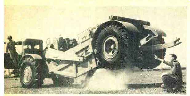
Fig. 1. A gas-explosion chamber built into this 18-ton vehicle is used
to produce an acoustic shock wave for oil exploration.
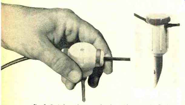
Fig. 2. Typical geophones employed to pick up sound reflections.
Reflection Seismology
Geophysical or seismic prospecting is the science of searching for petroleum, gas, or mineral deposits by making physical measurements on the earth. While many different techniques have been devised for making these measurements, one of the most effective and widely used in oil exploration is reflection seismology. In this technique, sound waves are generated in the earth. These waves travel through the earth and are reflected back to the surface from the various subsurface layers. These reflections are recorded, and the depth of the layers are computed by knowing the reflection times and the velocity of propagation. From this data, special maps of the subsurface are plotted. These maps are then interpreted by geophysicists who are able to determine if the subsurface structures are those which are usually oil bearing in nature.
If results of these measurements show conditions favorable to oil accumulation, further tests will be made and a pilot well may be drilled.
Reflection seismology is an acoustic-sounding technique.
In this technique, a generator source is used to produce a sound or shock wave that will penetrate the earth and be reflected back to the surface. The most widely used method of generating seismic waves is by detonating a charge of dynamite or other explosive. A hole, called a shot hole, is bored into the earth and the explosive is placed in it. The explosive is then detonated and a large impulse shock wave is produced. The wave travels through the earth in all directions and is reflected from the various subsurface layers. Reflections as deep as 20,000 feet have been recorded.
A newer method, developed by Burton McCollum, involves the dropping of a weight. A three-ton metal weight mounted on a large truck is dropped from a height of approximately nine feet. This creates a tremendous shock wave in the ground. This technique produces reflections which are just as useful as those produced by a dynamite blast.
Electric and hydraulic vibratory sources which vibrate the earth in a sinusoidal manner have also been used as seismic signal sources, but many of these are still largely experimental. The "Vibroseis ", a vibratory exploration technique developed by the Continental Oil Company, is already being used commercially.
(Editor's Note: Still another method of producing the shock wave was announced recently by Sinclair Oil Corp. A gas explosion chamber is mounted in the center of an 18-ton large-wheeled diesel-driven vehicle, called "Dinoseis." The chamber is held against the ground surface by part of the weight of the truck. When the gas mixture is exploded, a 100,000 foot-pound seismic impulse is produced (Fig. 1).) After the acoustic energy is radiated, it will travel through the earth with a velocity which is dependent upon the media through which it passes. Basic physics says that the velocity of propagation of acoustic energy is dependent upon the type of material through which the energy passes and other factors. For example, the velocity of sound waves is higher in rock than it is in clay soil. The earth's subsurface is made up of many different types of layers of rocks, soil, sand, and other substances. The velocity of propagation will change abruptly as the acoustic wave passes from one layer to another. Because of this velocity change, a reflection is produced. The exact nature of the reflection will depend whether the signal goes from a high-velocity zone to a low-velocity zone or vice versa. This reflection takes the form of a very small vibration of the earth which travels upward vertically toward the surface. This reflection is actually a low-frequency (10 to 300 cps ) sound wave.
Detection and Recording
The next step in this oil exploration technique is the detecting and recording of the vertical reflections. Here is where electronics plays a major role. Fig. 4 shows a cross section of the earth and a block diagram of the equipment used in the reflection method.
The reflections are picked up by a microphone-like transducer called a geophone. Fig. 2 shows two typical geophones.
The geophone, also called a seismometer or detector, is usually buried several inches in the earth. Care is taken to see that the geophone makes good contact with the earth so that it moves when the earth moves during a reflection.
A typical geophone consists of a coil of wire which is suspended by a spring and which moves in the field of a permanent magnet. When a reflection appears, a small vibration in the earth will be transmitted to the geophone and will cause motion between the coil and the permanent magnet. This causes a voltage to be induced into the coil which is a function of the nature of the vibration. The geophone is made so that it will respond best to vertical movement. A cable attached to the geophone carries the voltage to other equipment.
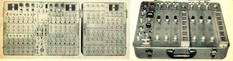
Fig. 3. Typical low-noise, high-gain, multichannel transistorized geophysical
amplifiers and filter units.
A single geophone is never used in practical work. A large number of geophones are arranged in various patterns over a large area to obtain diversity. Diversity improves signal-to-noise ratio. The geophones are wired together in various series-parallel combinations in order to obtain a satisfactory impedance match to other equipment.
The reflection signals from the earth are extremely weak.
Even though a large amount of energy is radiated by, say, a charge of dynamite, the voltage produced by a group of geophones is still too small to record directly. Noise in various forms also complicates natters. Just as in communications and radar systems, the signal-to-noise ratio is important and steps must be taken to improve it; otherwise, good naps of the subsurface will not be obtained.
The output voltage from the geophones is fed to a low noise, high-gain amplifier. This low-frequency amplifier provides extremely high gains in the 10- to 300-cps range. Care is taken in the design of these amplifiers to ensure a low noise figure. Fig. 3 shows two such geophysical amplifiers.
These amplifiers contain built-in low-and high-pass filters which help to improve signal-to-noise ratio by eliminating unwanted frequencies above and below the reflection signal frequency. These filters are normally of the constant-K LC type and are made variable to provide the desired filtering.
Some amplifiers also contain a 60-cps notch filter to eliminate power-line interference which tends to be a problem in many areas.
All good geophysical amplifiers contain a.g.c. circuits. In many cases even a form of delayed-a.g.c. is used. This a.g.c. system improves performance by allowing the amplifier to operate over a wide range of input signal amplitudes without distortion. Another feature of some geophysical amplifiers is programmed gain. Programmed-gain circuits allow the gain of the .amplifier to change with time. Since it takes a longer time for deep reflections to return to the surface than it does shallow reflections, naturally the deeper reflections will show up much smaller in amplitude on the record.
In some cases it may take five or six seconds from the time the seismic signal was radiated for the most greatly attenuated, deeper reflections to return to the surface. The amplifier with programmed gain changes its gain with time and thereby brings all the reflection signals to approximately the same amplitude level.
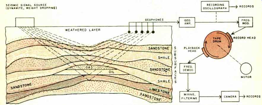
Fig. 4. Cross section of earth showing the subsurface layers and a block
diagram of associated electronic instrumentation.
After considerable amplification and some filtering, the signals are ready to be recorded. In order for the geologist or geophysicist to analyze the reflection information, it must be recorded and put into a suitable form. The most common form is a photographic record showing a number of reflection recordings. These are normally arranged so that the reflection signals from each dynamite blast or weight drop appear one beneath the other. In this way, line-ups of reflection signals will be easier to detect. This record is made by applying the seismic signal to a light galvanometer. The light is flashed onto light-sensitive paper which is moved past the galvanometer. This paper is processed and a record is produced. Timing lines are also put onto the record so that the geophysicists may know how long it takes the radiated signal to travel into the ground and to be reflected back to the surface. These timing lines are usually graduated in steps of 10 milliseconds, and the entire record can be anywhere from four to six seconds long. A device for producing such a record is called a recording oscillograph, and a typical unit is shown in Fig. 5. Fig. 5 also shows a seismic reflection record made on a similar recording oscillograph.
Magnetic tape recording systems are also used, particularly in poor record country where additional filtering and other processing must be done to obtain usable reflection data.
The magnetic tape record can be sent to a central laboratory for processing. A record is made by placing a magnetic tape about four inches wide and three feet long on a large rotating chum. The magnetic record and playback heads are placed adjacent to this drum. The drum revolves as dynamite shots or weight drops are produced and the resulting reflection signals are recorded on the tape.
The recording technique actually involves frequency modulation. The amplified reflection signals frequency-modulate a high audio-frequency carrier (2-5 kc.) . It is this modulated carrier that is recorded on the tape. This FM technique results in a better recording than would be obtained if no modulating system were used. It also eliminates the need for a bias signal which is usually required in magnetic tape recording systems to reduce distortion inherent in magnetic recording. Although FM is generally favored, standard magnetic tape biasing techniques are also used successfully in recording systems of this type.
A typical FM modulator consists of a free-running multi vibrator which oscillates at a frequency of 4 kc. The frequency of this oscillator is dependent upon the RC time constant used in the grid circuits. This oscillator is frequency modulated by the reflection signals. A tube acting as a variable resistance is connected in the grid circuit. As the incoming reflection signals are applied to this tube, its resistance changes, thus changing the circuit time constant and the frequency of the oscillator.

Fig. 5. (Left) A recording oscillograph of the type that is employed
to produce seismic records for use in oil exploration. (Right) Typical
seismic reflection record. Artificially induced shot break indicates when
seismic energy was first radiated. Refracted energy is the first arrival
of seismic signal at the geophones. This is energy refracted from the
first high-velocity zone below the surface. The reflections indicate a
change in velocity or the boundaries of reflecting layers. Reflections
are picked by noting where the signals of each trace line up or where
the peaks and troughs appear to fit into one another. Other reflections
besides the ones that are obvious in this figure can be picked by close
observation.
The FM signal from the playback head is amplified and clipped and made into a varying-frequency rectangular wave.
It is then differentiated and the resulting spikes trigger a monostable multivibrator. One fixed-amplitude, constant duration pulse is produced by the monostable circuit for each trigger spike. The pulses are then integrated or averaged in a suitable low-pass filter. The output is the original geophysical signal.
After the reflection signals have been recorded, they can be processed in various ways. Mixing (compositing) and filtering are the most commonly used processes, and both methods improve the signal-to-noise ratio.
After a number of shots have been recorded, the resulting reflection signals can be mixed together. The reflection signals may be obscured by noise in all of the recordings, but because' the noise tends to be random it will cancel to some extent. The reflection signals, however, being the same on each record, will add. Practice has shown that the signal–to-noise ratio improves approximately as the square root of the number of records composited. Each trace in Fig. 5, for example, is actually a composite of 320 individual records.
In addition to the filtering in the geophysical amplifiers, special filters are used in cases where the signal-to-noise ratio is low. These filters have many configurations and are largely of the analog type. Digital-filtering techniques have also been developed. Because of the transient nature of seismic signals, filter requirements are rigid and care must be taken to see that the filter does not distort the signals and give false results.
In addition to filtering and mixing, processing also includes corrections. In order for the geophysicist to obtain a true picture of the various subsurface layers, there are certain characteristics of the earth that must be taken into consideration.
The uppermost layer of the earth, the weathered layer, will give false reflection data if it is not corrected. Since it varies in thickness with location, information regarding this weathered layer must be obtained before suitable reflection data can be obtained.
Ground elevation and geophone placement must also be considered. Since-the geophones are spread over a large area, the elevation may be different for some geophones than for others. Also the distance between the signal radiator and the geophones may be changed during the shooting. Connections must be made. Other corrections of various kinds must also be made depending on the equipment and methods used.
Obtaining the Information
To obtain information about the oil-bearing properties of a particular part of the earth, a crew of men is sent into the field along with the equipment just described. Since all of the work is done in the field, the equipment must be portable.
It is made so by mounting it in trucks. For dynamite operations, shot-hole drilling apparatus must be taken, and with the weight-drop technique, a large truck must be provided to carry the weight and its associated equipment.
An instrument or recording truck carries most of the electronics. The recording equipment and amplifiers are mounted in this truck. Because of the complexity of this truck, a skilled electronics field technician must be present to set up, operate, and maintain this unit in the field.
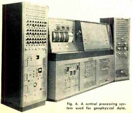
Fig. 6. A central processing system used for geophysical data.
Fig. 7. One of our nuclear explosion detection stations.
The equipment used in oil exploration is sometimes mounted in boats so that water areas may be worked. Many oil discoveries have been made beneath large bodies of water--such as the Gulf of Mexico.
While most of the work of producing data for the geophysicist is done in the field, many times recordings are sent to a central processing point. The processing center may do all or part of the filtering, mixing, and correcting usually necessary and, in addition, may handle the work of several field crews. A typical central processing unit is shown in Fig. 6.
Other Exploration Techniques
The exploration technique described here is only one of a number of methods used in finding oil and investigating the interior of the earth. Others include refraction seismology, magnetic and gravity measurements, and well logging. Like reflection seismology, most of them are dependent upon electrical or electronic instrumentation.
Refraction seismology is quite similar to the reflection method in that it requires almost exactly the same equipment. The technique makes use of the refracting properties of the subsurface layers. This technique is generally inferior to the reflection method because it does not give an exact picture of the subsurface. It is useful in many instances, however, particularly where it is desired to determine the velocity of propagation in certain areas.
In well logging, a deep hole is drilled in the earth and instruments are lowered to the bottom. As the instruments are pulled up, measurements are made on the rock and soil and a chart or log is plotted as a function of depth. Among the properties measured are acoustic velocity, electrical resistivity, density, self potential, gamma-ray radiation, and others. Geologists have said that this is one of the most useful of all of the various exploratory techniques used.
The Mohole and Vela Uniform
While a large percentage of the electronic instrumentation used in the geosciences is concerned with locating oil and gas deposits, electronics is also helpful in other areas. Two recent interesting uses of electronics in the geosciences are the drilling of the Mohole and Vela Uniform.
The Mohole project is an attempt to drill through the outer crust of the earth into the mantle or inner earth. The mantle comprises about 80% of the earth's volume, but little is known of its character. Knowing the nature of the inner earth will aid scientists in proving or disproving theories and the history of the earth.
The Mohole will be drilled at sea because the mantle is closer to the surface under the sea than it is under land.
Naturally, this brings on many complications. The drilling ship must, at all times, be accurately positioned over the hole being drilled regardless of the condition of the weather and the sea. This requires a special drilling ship as well as an excellent positioning system. The positioning system will make extensive use of electronic techniques. Electronic instruments will also be used to log the hole as it is drilled. Reflection and refraction seismic tests have been run over the water areas that are being considered as drilling sites. We can expect to see some interesting results of the experiment.
Vela Uniform is part of the government's research project for the development of a satisfactory arms control in the form of an underground nuclear blast detection, identification, and location system. The entire program is dependent upon electronic instrumentation. Seismological observatories or detection stations will be set up at carefully chosen locations over the world. These stations will be equipped with seismometers, amplifiers, processing and recording instruments, and other devices necessary to the detection of nuclear blasts and other seismic disturbances.
Underwater seismometers with telemetry equipment will also be used. Fig. 7 shows a typical detection station for nuclear explosions.
As advances are made in electronics, so will advances be made in the geosciences. It is hard to predict what lies ahead but it will no doubt be of considerable value to mankind-and much of it because of the contributions made by electronics.