(source: Electronics World, Aug. 1964)
By ED BUKSTEIN / Northwestern TV and Electronics Institute
Step-by-step description of how computer is programmed in order to perform simple calculations automatically.
ACCORDING to a popular belief, the outstanding characteristic c of the modern digital computer is its amazing speed. Although it is true that the computer operates with electronic swiftness rather than the motor-and-gear speed of the desk-type adding machine, this is not its most outstanding characteristic. It is the automatic sequencing of its internal operations that makes the computer something more than just a king-size adding machine. What would be the use of a machine capable of thousands of mathematical operations per second if it were not automatic? Could an operator punch the keyboard fast enough to keep the computer supplied with data and to control the internal operations? Obviously not. The automatic digital computer must, therefore, contain a memory unit capable of holding large amounts of data and instructions, and these must be automatically extracted from memory as they are needed.
Because computers employ two-state ("on-off") type of circuits, data and instructions must be handled in binary form. The binary system of notation employs only two symbols, 0 and 1, and various combinations of these symbols are used to represent numerals and letters of the alphabet.
Several such representations are shown below:
001001 =9 010111 =X 110101 =E 001011 =!
Each numeral, letter, etc. is represented by a unique group of six bits (binary digits). There are a total of 64 different six-bit combinations-more than enough to represent all the letters of the alphabet, the numerals from 0 through 9, punctuation marks, and other special symbols. A code recently adopted by the American Standards Association employs seven-bit groups. Since there are 128 seven-bit combinations, this code handles all the alphabetic and numeric characters and special symbols, and leaves many other combinations to be used for special control purposes.
Computer Words
Two types of information are stored in the memory unit of the computer: data words and instruction words. Data words comprise the information to be operated on-the "given" information in a mathematical calculation, for example. Instruction words indicate the types of operations to be performed ( addition, subtraction, etc.) and also specify the location in memory of the data words to be added, subtracted, etc. The composition of typical instruction and data words is illustrated in Fig. 1. Decimal digits are shown but, as described previously, each digit is represented in the computer by a group of binary bits.
As indicated in Fig. 1. the data word uses one digit position to indicate sign (plus or minus). A five-digit number is shown but most computers employ longer words for greater precision. Data words are not always numerical. In business data processing, for example, they often contain alphabetical characters to represent customer names, street addresses; and similar material.
An instruction word consists of two parts. The operation code specifies the type of operation to be performed (multiplication in the example shown in Fig. 1) . The address part of the instruction word specifies the location in memory of the data word to be used. The instruction word in Fig. 1 therefore means that the data word located in address 1306 is to be multiplied (times the number already in the arithmetic section of the computer). Operation codes are selected rather arbitrarily by computer designers. The code for multiplication, for example, may be .32 in one computer, 61 in another, and 07 in still another. In Fig. 1, the code is 25. A list such as shown is a repertoire of instructions and most computers have a repertoire of 50 to 150 instructions. Not all operation codes specify arithmetic operations. Typical non-arithmetic operations are: clear the memory, clear the arithmetic section, transfer the data from arithmetic section to memory, write on magnetic tape. examine the contents of the arithmetic unit to determine if it is plus, minus, or zero.
The Program
In the memory section of the computer, the location of each word is identified by an address number. If the memory can hold 10.000 words, for example, the addresses can be identified by numbers ranging from 0000 to 9999. All of the instruction words needed to perform a particular data processing job are known collectively as the program and these instructions are stored in successively numbered addresses in the memory. If the program requires 500 instruction words, for example, these could be stored in addresses 0000 to 0499.
The remaining addresses, or as many as are needed, would then be available for holding the data words. All of the data and instruction words are loaded into the memory at the start of the program, and the instructions are then read out one at a time. This establishes the basic rhythm or machine cycle: obtain an instruction from memory, perform the operation specified by the instruction, obtain the next instruction from memory, and so on.
A list of instructions necessary for performing a relatively simple calculation is given below. Actually, a computer would not be used for the solution of such a simple calculation, but the principles are the same. Suppose that it is desired to calculate M in the following equation:
iq--XZ
-¡ Y2 R
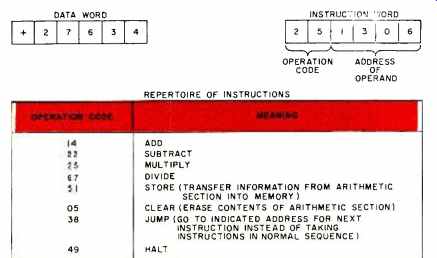
Fig. 1. Data and instruction words are stored in memory of computer.
instruction words are those that are employed to determine which operations
are performed on the data words.
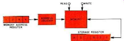
Fig. 2. Information can be transferred to or from memory. Address register
and decoder determine which word is transferred.
The numerical values of X, Z, Y, and R are stored as data words in the memory. Assume that they are stored at addresses 1500, 1501, 1502, and 1503 respectively. The following list of instruction words would also be stored in the memory and, when performed in sequence, will yield the solution to this equation. In each instruction word, the first two digits represent the operation code as listed in Fig. 1.
1. 050000 6. 141500
2. 141502 7. 251501
3. 251502 8. 141600
4. 511600 9. 67150:3
5. 050000 10. 511601
11. 490000
The first instruction (050000) therefore serves to clear the arithmetic unit of any data which may remain from a previous calculation. The second instruction acids the value of Y from the storage address 1502 into the arithmetic unit.
Instruction number three causes Y from the address 1502 to be multiplied by Y in the arithmetic unit. The contents of the arithmetic unit is now Y2, and this value is stored (instruction four) in storage address 1600. Instruction five now clears the arithmetic unit. The sixth instruction brings X from address 1500 into the arithmetic unit. Instruction seven causes multiplication by Z so that the arithmetic section now contains the product XZ. The eighth instruction causes the addition of Y2 from address 1600, and the arithmetic unit now contains XZ +Y2. Instruction nine divides by R, and the arithmetic unit now contains the value of 111. This value is stored by instruction ten at address 1601. Instruction eleven then halts the machine completely.
Memory Operations
In addition to its main memory, the computer contains several one-word storage units known as registers. Information can be transferred from a register to the memory or vice versa. A read-from-memory type of operation is illustrated in Fig. 2. When a pulse is applied to the "Read" terminal, one word is transferred from memory to the storage register.
The memory address register and the address decoder determine which word will be transferred. In Fig. 2, the memory address register is set to 1294. The "Read" pulse therefore transfers the word from this address to the storage register. As indicated, the word is +51832. A store instruction (write-into-memory) is accomplished in a similar manner except that the pulse is applied to the "Write" terminal instead of the "Read" terminal. This pulse will cause the word in the storage register to be transferred into memory (at an address determined by the setting of the memory address register).
Fig. 2 illustrates the general technique of moving words into or out of memory. Data words are generally transferred into arithmetic registers, and instruction words are transferred into the instruction register. An instruction register is illustrated in Fig. 3. After an instruction word has been transferred into this register, the operation and address parts of the instruction are dealt with separately. According to which operation code is in the instruction register, the operation decoder produces output at one of its output terminals.
This output then controls the pulse distribution circuits to activate those circuits needed for the called-for operation.
If the operation code specifies addition, for example, the pulse distribution circuits will activate the adder in the arithmetic unit of the computer. The pulse distribution circuits also cause the address part of the instruction word to transfer into the memory address register. The data word at this address will therefore transfer into the adder.
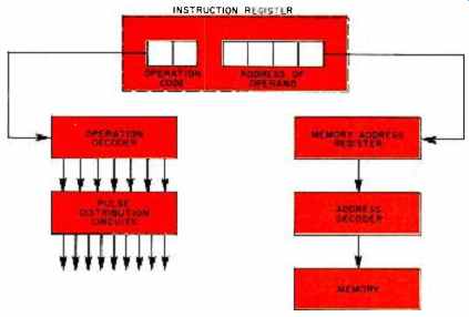
Fig. 3. Instruction register holds instruction word during the time
that the called-for operation is performed.
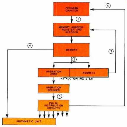
Fig. 4. Generalized diagram showing the flow of data in computer.
Data Flow
Fig. 4 shows a generalized block diagram illustrating data flow in a computer. Assuming that the address of the first instruction word has previously been placed in the program counter, the following events occur.
1. The address in the program counter transfers into the memory address register.
2. The instruction word at this address transfers from memory into the instruction register.
3. The address part of the instruction word transfers from the instruction register to the memory address register.
4. The data word from this address transfers to the arithmetic unit (or other destination according to the operation code).
5. The operation decoder, responding to the operation part of the instruction word, controls the pulse distribution circuits so that the called-for operation will be performed.
6. The pulse distribution circuits supply an input to the program counter, increasing its count by one. Since the instruction words are in sequential addresses in memory, the program counter now contains the address of the next instruction to be executed. The above steps are repeated over and over until all of the instructions have been performed.
Not only can the computer perform a series of instructions in sequence, it can be programmed to modify this sequence. One type of instruction that causes the computer to abandon the normal sequence is the branch or jump instruction. This causes the computer to skip to a specified instruction instead of taking the next instruction in the normal sequence. jump instructions are often made conditional, that is, the jump occurs only if a certain condition exists.
A typical instruction of this type causes the computer to "jump" if the number in the arithmetic unit is negative.
Another technique commonly employed by programmers is to include an instruction which directs the computer to return to a previous instruction. This puts the machine into a loop of instructions which it repeats over and over.
A counter circuit keeps track of the number of times the loop has been repeated and allows the machine to escape from the loop after a predetermined number of repetitions. Such loops can considerably reduce the total number of instructions employed in the program.