(source: Electronics World, Aug. 1964)

By RICHARD LaCOSTE
Spacecraft tracking stations are not always located on hard ground. In fact, a pair of the most highly sophisticated stations are mounted on two specially equipped ships that can he located on any ocean.
THE Atlantic Missile Range (AMR) extends from Cape Kennedy, Florida, to the Indian Ocean, some 10,000 miles away. This range is used to provide exact data on all phases of a missile's performance from launch to termination of flight.
To accomplish its mission, the AMR has established ground tracking stations at Grand Bahama Island, Eleuthera Island, Trinidad, Ascension Island, and Pretoria, South Africa.
Another network for use in manned space operations is the former Mercury Ground Communications Network, now part of the Manned Space Flight Network controlled from Goddard Space Flight Center, Greenbelt, Md. This network also has ground-based tracking stations scattered around the earth.
Both of these tracking networks also require the use of a pair of floating tracking stations that can be stationed at sea in any part of the globe to cover otherwise empty sectors of the missile's planned flight path.
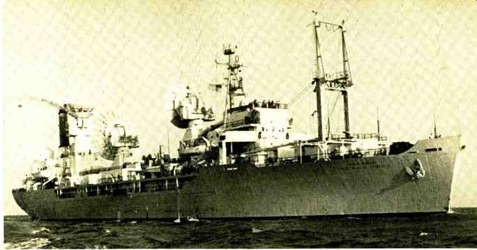
--------The "General H. H. Arnold" is a converted hoop
transport and is the world's largest and most heavily instrumented missile
and space tracking ship. The interior arrangement shows how bulk of the
electronic equipment is arranged in the vessel.
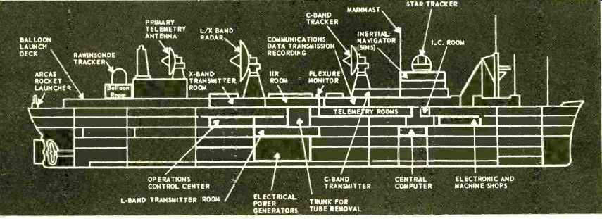
STAR TRACKER
This is the purpose of the Advanced Range Instrumentation Ships (ARIS), the "General H. H. Arnold" and the "General Hoyt S. Vandenberg." These two vessels, part of a fleet of 10 ships, carry the very latest in electronic equipment for reception and recording of spacecraft telemetry, tracking, and voice communications in the case of manned flights. Navigation equipment on board these ships is capable of placing its position within yards relative to Cape Kennedy, many thousands of miles away.
ARIS instrumentation is divided into eight subsystems: operations control center; integrated instrumentation radar; stabilization; navigation; communications /data handling; telemetry; meteorological; and timing.
Operations Control Center
This center functions as the command post during tracking missions and systems tests. The centralized control facility provides for smooth internal operation and assures proper integration of the ARIS station into AMR operations.
During missions, center personnel coordinate with other AMR stations, aircraft and ships; review system and subsystem status; assure correctness of ship's position, speed and heading; monitor and countermand subordinate decisions; and select the source of sensor designate information.
Integrated Instrumentation Radar
This consists of three radars operating at C (5.7-6.2 kmc.), L (.39-1.55 kmc.), and X (5.2-10.9 kmc.) bands. The primary tracking device is the C-band radar using a parabolic reflecting antenna thirty feet in diameter. Precision has been stressed in the construction of the antenna. The radar provides complete tracking data on re-entry bodies from the launching of the missile to its impact. Similar to C-band radar is the L/X-band radar. This uses a dual-frequency antenna forty feet in diameter. The center 18 feet are used for X-band radar and the remaining portion for the L-band radar. These radars also provide data on reentry.
Stabilization and Navigation
The exact location of the ship must be known if the received satellite tracking data is to be of any value. A complex navigation system continuously supplies this information on the ship's position, heading, speed, and vertical reference.
The system consists of: SINS (Ships Inertial Navigation Systems) , a navigation control console; a water speed-measuring system (E-M log); a star-tracker; and a Mk-19 gyrocompass and sonar bench mark equipment.
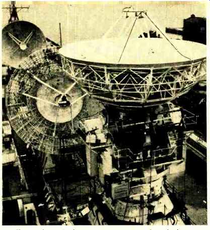
--- Three radar and telemetry antennas are used on the larger ships.
In the foreground is the 30-ft. telemetry antenna.
The heart of the system is SINS. It contains three gyros and two accelerometers. Because of gyro drift, this inertial system develops errors that increase with time. The drift or precision error is determined by a star fix. A star-tracker measures star altitude by locking onto the star's position, then a computer solves the celestial problem and a navigation fix is made. Sonar bench marks also are used as a navigational aid for updating SINS' accuracy. The bench mark is dropped over the side in a known position. It has an acoustic transponder mounted on a buoyant tank which is anchored by a battery container. When the sonar set is triggered, a reply is received from the transponder. The elapsed time, as a function of range, is measured to each beacon thus locating the ship with respect to the bench marks.
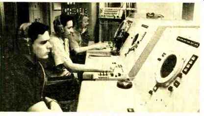
--------Integrated instrumentation radar room of the "General H.
H. Arnold. This system uses alternate polarization of three radars to
gather 3.6 million bits of data per minute about the trajectory and impact
point of the incoming vehicle.
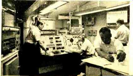
--------Navigation area of the "General H. H. Arnold." Accuracy
of this system is such that it can locate the ship within yards of Cape
Kennedy although vessel is thousands of miles distant.
Communications
The highly sophisticated communications system is designed to meet all external and internal needs. It includes one of the most powerful radio communications systems ever installed on board a ship. One 10,000-watt and two 2500 watt high-frequency transmitters provide complete long range voice, teleprinter, and high-speed data communications up to 10,000 nautical miles from Cape Kennedy. An interior communication network has been developed for use by the instrumentation personnel. This network consists of three types of intercom stations, each varying in channel capacity, which link key shipboard instrumentation personnel.
Data Handling
The data handling system consists of the central data conversion and control equipment and a Univac 1206 stored--program digital computer. The conversion equipment has two main purposes: to serve as an interface between the major systems (SINS, C-band radar, L/X-band radars, telemetry) and the Univac 1206 computer, and to store all trajectory and non-trajectory data collected during a mission.
The overall accuracy of the data conversion equipment is 0.4 percent. All stored information is in digital form, having been transformed by the conversion equipment. The data processing needs are met by the Univac 1206 digital computer. This is a general-purpose machine of small size and high resistance to shock, vibration, and unusual climatic conditions. The computer performs such functions as system checkout, target acquisition, target tracking, data format, data transmission, navigational fixing, and information updating. Most information is stored on magnetic tape.
Telemetry
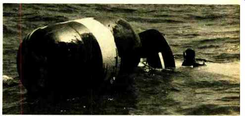
------ An inflated bag is secured to an Atlas nose cone after it has landed in
the ocean. This particular nose cone flew 5000 miles.
The telemetry system is used for acquiring, tracking, receiving, and pre-detection recording of telemetry data from the re-entry vehicle. It is capable of either independent or integrated operation with other sensors, or it can be used to aim other tracking sensors to a proper angle of acquisition, and it can be slaved to the C-band radar or computer for position information. A 30-foot parabolic antenna is used for reception of telemetry signals.
Meteorological
To aid in the analysis of missile performance and the scheduling of tests, the ARIS vessels provide data on atmospheric pressures, density, wind direction, and speed of sound.
This is accomplished through surface weather equipment, weather balloons, and high-altitude ARCAS rockets.
Timing
The timing system provides real-time codes and indexes for time correlation of pertinent data. These codes are distributed in various digital serial formats throughout all the systems for accurate time correlation of all recorded data.
The time code and indexes will maintain time correlation, relative to Cape Kennedy timing, within 10 microseconds at distances up to 10,000 miles. Two radio systems provide this synchronization.
The general operational procedure of the ARIS ships will be as follows:
1. The ships will sail prescribed courses in the vicinity of the expected impact points, measuring position accurately with reference to surveyed sonar beacons.
2. The communications system will receive post-burnout signals from Cape Kennedy.
3. The computer will integrate the equations of motion of the missile faster than real time to determine an acquisition point prior to the missile's arrival.
Using measured values of latitude and longitude from SINS, a continually corrected stable acquisition point, relative to the ship, is acquired.
4. SINS will supply heading, pitch, and roll through the Central Data Conversion and Control Equipment (CDCE) to the computer, which combines these with the acquisition point. The result is a digital acquisition orders.
5. CDCE converts these orders to synchro voltages for aiming the antennas to the proper position.
6. The tracker which first acquires the missile is designated the master.
7. The other antennas are slaved through CDCE with corrections for ship's flexures.
8. When the C-band radar acquires the missile, CDCE converts the trajectory and signal strength to digital form and records on magnetic tape.
9. The missile path is plotted from the acquisition point to impact.
10. After impact, recorded data is transmitted to waiting, aircraft via telemetry and balloon snatch.
The prime mission of ARIS is accurate tracking and data gathering of reentry vehicles. However. these ships also will participate in future projects like Dvina-Soar, Gemini, Apollo, and other.