(source: Electronics World, Mar. 1966)

By SIDNEY L. SILVER
These important components are widely used in industry for indicating small changes in voltage and current, and operating control circuits when preset values are reached.
In the field of automation there is an increasing need for simple, inherently stable control-system components to perform the various process functions with a high degree of reliability. One of the most useful and versatile of these components is the meter relay, which combines the functions of both an indicating meter and a control relay. Meter relays are electro-mechanical devices which are capable of detecting and indicating extremely small changes in current or voltage; and when these measured quantities reach preset limits as determined by adjustable control points, a set of built-in relay contacts effect the opening and closing of auxiliary circuits.
These instruments are sensitive enough to respond directly to low-level signals ( without need for any further amplification) from any process variable that can be measured electrically through the use of a suitable transducer. They are widely employed to monitor and control such variables as temperature, radiation level, pressure, moisture content, pH, motor speed, and a multitude of other physical and chemical phenomena.
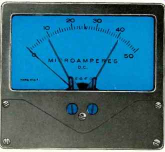
Fig. 1. Typical current-sensitive meter relay. This particular unit incorporates
two screw-adjustable contact pointers
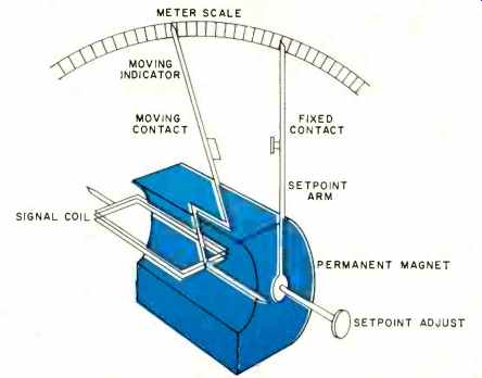
Fig. 2. Cutaway diagram of non-locking meter relay. The various leads for
control signal and load relay are not shown.
Meter relays can function as limit-control devices in which control action is initiated when the safe operating limit of a measured variable is reached. In this mode of operation, associated equipment is shut down and protective warning devices are actuated. The unit is then reset manually each time the variable reaches a predetermined control point.
In a programmed operation, meter relays can maintain an automated process at a given level by automatic "on-off" control. In this mode of operation, the desired control action occurs at a preset limit, but the device continues to sample the variable periodically without interrupting the load circuitry. Under these conditions, corrective control action ceases when the measured variable returns to the proper level.
Meter relays may be broadly classified into three categories according to their contact arrangement: the nonlocking, locking, and continuous-reading types. In addition, a new concept in meter-relay design is the optical type which incorporates solid-state switching to eliminate the usual physical contacts. A typical, commercially available meter relay with two setpoint arms is shown in Fig. 1.
Nonlocking Meter Relays
The nonlocking meter relay is a sensitive contact device which depends solely upon the current flowing through a moving coil for maintaining contact pressure. Operating on the d'Arsonval principle, as shown in Fig. 2, the moving coil is attached to an indicating pointer and suspended on jeweled pivots in the flux gap of a permanent magnet. When the coil is energized by a signal current, a torque is produced which rotates the coil and causes the pointer assembly to move across a meter scale in direct proportion to the signal passed through the coil. The indicating pointer is restrained by a pair of control springs (not shown) which serve as current leads to the coil and restore the pointer to zero when the signal current is removed.
In addition, the instrument has an adjustable setpoint arm which is rotatable along the same axis as the moving indicator and which may be manually adjusted to any desired point on the meter dial. A moving contact is carried by the indicating pointer and a fixed mating contact is mounted on the setpoint arm. Some types are provided with two setpoint arms (each carrying a stationary contact) which are adjustable for high and low operating values.
Fig. 3A shows the basic circuit of a nonlocking meter relay in which the moving contact and the fixed contact form a series circuit with an external load relay that is energized by a d.c. source. When a control signal applied to the moving coil causes the indicating pointer to reach a predetermined setpoint, the contacts are forced together, thus closing the load circuit. If, however, the signal level falls below the set-point, the meter relay resets itself automatically, and the signal coil restores the moving element to a position relative to the amount of current in the coil.
One of the basic problems of the nonlocking arrangement is the small force applied to the moving coil element to close the relay contacts. Since only a few milligrams of pressure exist at the point of contact, it is necessary to employ a high-torque meter movement in order to produce a reliable and definite contact action. To increase contact reliability, a suitable contact material such as platinum, is generally used because of its extremely low contact resistance and its relatively high resistance to oxide film formation. In addition, one of the contacts is made flexible in order to provide a wiping action which keeps the contacts clean. To avoid arcing which may produce contact corrosion, the open-circuit voltage across the contacts is limited to about 6 volts d.c.
Generally, the use of nonlocking meter relays is restricted to applications where the control signal abruptly rises or falls below a predetermined setpoint so that the make or break period of the contacts occurs quite rapidly.
Locking Meter Relays
To offset the disadvantage of low contact pressure imposed by the nonlocking arrangement, locking meter relays were developed to provide additional torque to the signal coil. In this configuration, an auxiliary winding, referred to as a locking or aiding coil, is integrally wound on the same form as the signal coil. As shown in Fig. 3B, the locking coil is connected in series with the load relay circuit across the d.c. power source. When the indicating pointer reaches setpoint, sufficient current flows through the locking coil to boost the signal coil rotation, thus maintaining firm contact pressure (on the order of 2 grams).
Once the load relay is pulled in by the meter-relay contact action, it remains energized irrespective of the signal current value, so that the pointer no longer responds to input signals.
To reset the device, a push-button switch, in this case manually operated, interrupts the d.c. circuit and opens the locked meter-relay contacts. If the input signal has fallen below the lock-in value, the meter-relay contacts remain separated and the load relay drops out. However, if the signal level is above the preset level, the contacts promptly close again.
Since the moving contact is spring loaded, the contacts are kicked apart forcefully when the load circuit is broken, thus overcoming any tendency for the contacts to stick. The spring pressure allows operation of locking meter relays at contact ratings up to 25 ma. at 125 volts d.c. For this reason, these devices are particularly adaptable to slowly changing input signals.
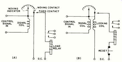
Fig. 3. (A) Basic circuit diagram of the nonlocking type, (B) Locking meter
relay circuit shown here with manual reset.
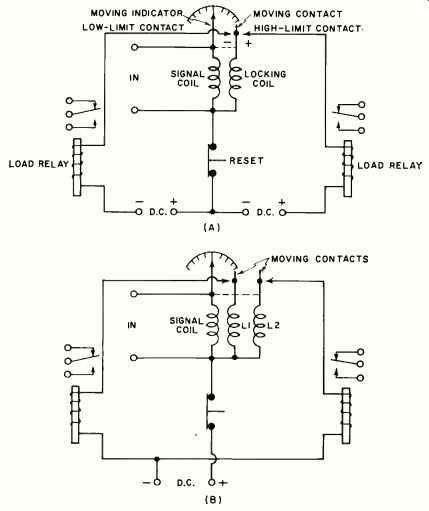
Fig. 4. (A) Double-contact type using a three-terminal power sup ply. (B)
Dual locking-coil arrangement with 2 moving contacts.
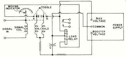
Fig. 5. Continuous-reading type with automatic-reset feature.
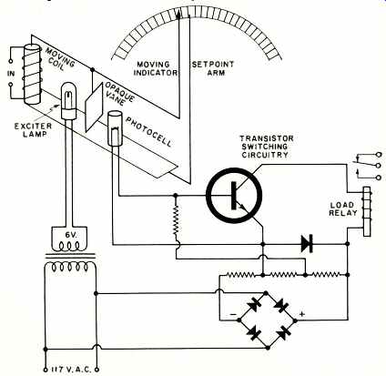
Fig. 6. Pictorial-schematic diagram of an optical meter relay.

Fig. 7. Automatic temperature controller with high-limit relay.
In applications where both upper and lower limits for a specific current are required, a double-contact meter relay is employed. This unit is provided with two setpoint arms whose contacts are adjustable for high- and low-level operating points. Thus, when an input signal rises or falls to either of the predetermined control points, a load relay is tripped and control action is initiated.
In the double-contact arrangement shown in Fig. 4A, both a positive and negative d.c. power source are required. By this means, the voltages applied to the fixed contacts are of opposite polarity, so that the locking-coil torque is properly directed to maintain pressure on either contact. To lock the high-limit contact upscale, for example, a positive polarity must be applied to the high-limit contact to permit current to flow up through the locking coil. Conversely, current must flow through the coil in a reverse direction to lock the low-limit contact downscale.
Fig. 4B shows an alternate arrangement which employs a single d.c. power supply but requires dual locking coils. In this circuit, the meter relay contacts lock with the same polarity on both high- and low-level limits. The locking coils are wound in opposite directions in order to maintain the proper direction of force. Since a voltage of the same polarity appears on each of the fixed contacts, the coil L2 locks in an upscale direction and the coil L1 locks downscale.
Continuous-Reading Meter Relays
A unique arrangement which combines both the high contact pressure of the locking meter relay and the instantaneous reset of the nonlocking type, is the continuous-reading device shown in Fig. 5. The resettability feature of this unit eliminates the need for interruption circuits and provides a continuous indication of the monitored variable both above and below setpoint.
In the continuous-reading design, a V-shaped toggle arm is mounted on the setpoint arm in such a way that it pivots behind the indicating pointer. The toggle carries a pair of contacts (A and D) which form two separate circuits through a center-tapped load relay. In addition, the moving pointer has two isolated contacts (B and C) positioned so that moving contact C touches toggle contact D when the pointer reaches setpoint in the upscale direction; and contact A touches contact B as the meter moves downscale. A d.c. power source is connected to the load relay which provides a biasing current of sufficient amplitude to hold the load relay in, but not enough to energize it initially.
When the moving pointer reaches setpoint in the upscale direction, capacitor C discharges through one half of the load relay and the resultant current surge pulls the relay in.
Simultaneously, booster coil L2 is energized and drives the pointer further upscale so that enough torque is added to the pointer to trip the toggle. This action opens the booster circuit to the load relay, but the biasing current holds the relay in.
When the pointer returns downscale, contacts A and B close, and capacitor C discharges through the other half of the load relay, thus bucking the biasing current. At the same time, booster coil L1 is energized, which drives the pointer further downscale, snaps the toggle back to its original position, and opens the bucking circuit. By this particular sequence of action, the moving pointer indicates input signal values continuously while the booster circuits provide positive make and break action of the associated circuits.
Optical Meter Relays
A recent development in meter-relay design is the optical or contactless type which provides continuous indication above and below setpoint without the use of physical contacts. Fig. 6 illustrates a typical optical meter relay which achieves its non-physical contact action through the use of a light beam and photoresistive cell. In this configuration, the setpoint arm carries both an exciter lamp and photoconductive cell arranged so that the light source is projected on the sensitive surface of the photocell.
When the moving pointer is below setpoint, the light beam falling on the cell causes its resistance to drop, which cuts off the transistor switching circuitry and maintains the load relay in an unenergized state. When the pointer reaches setpoint, a low-mass aluminum vane carried by the indicator interrupts the beam of light illuminating the cell. The resulting increase in cell resistance allows the transistor switch to conduct, which pulls in the load relay and initiates control action. To obtain a high/low setpoint meter relay, a separate light source and photocell are provided for each setpoint arm that is employed in the device.
Automatic Control Applications
In many complex automation processes, it is necessary to maintain a variable, such as temperature, at a given level by "on-off" control of associated circuitry. Since meter relays of the locking type do not drop out when current through the signal coil is reduced, an automatic interrupter circuit may replace the manual reset button to periodically separate the locking contacts. This "on-off" action allows the meter relay to intermittently sample the process being controlled in order to determine whether further control action is required.
Fig. 7 shows a temperature control unit utilizing a locking meter relay, in which the contact action provides high-limit automatic control and the indicating element gives direct readings in both Fahrenheit and centigrade. In this circuit, a thermistor sensing element ( de signed for negative-temperature coefficient) forming one arm of a d.c.-energized bridge, is mounted near the source of heat to be controlled.
Initially, the bridge is balanced by R1 to provide the desired operating point and the setpoint arm is adjusted for the required high-temperature limit. Control action begins when an increase in temperature ( as small as .075°F) unbalances the bridge and causes a current flow through the meter relay signal coil.
This action causes the load relay to pull in and switch off the heating circuit.
When the temperature drops below the control point, the load relay drops out and the heat is switched on again.
To test the temperature periodically, the sampling interrupter switch is actuated by a notched cam which, in turn, is continuously driven by a small synchronous motor. The frequency of interruption is determined by the speed of the motor (usually 1 rpm) and the number of notches on the cam. To avoid breaking the load relay circuit during the brief periods of interruption, capacitor C is placed across the relay coil to hold in the relay when the sampling switch is open.
A common application of meter relays in industrial automation is the control of positioning devices as a function of mo tor current. During an automatic grinding operation, for example, a meter relay can utilize the fluctuating load current of a drive motor to precisely regulate the grind-pressure applied to a work-holding fixture. The fixture is positioned by a feed motor which, in turn, is driven by a pair of load relays ( RL1 and RL2 in Fig. 8) which operate from a low-limit and high-limit contact, respectively.
In this application, an a.c. signal de rived from the current drawn by the grinding wheel drive motor is rectified to d.c. and fed to the signal coil of a double-contact meter relay. Initially, the meter-relay setpoint arms are adjusted for minimum and maximum drive currents. In normal operation, with the proper drive motor current applied to the rotary grinding wheel, the correct pressure is applied to the workpiece and no control action occurs.
However, when the drive motor current decreases below the normal range (indicating that grinding pressure is too light), the moving indicator and the low-limit contact lock downscale and load relay RL1 is energized. The load contacts start the feed motor in a direction which advances the fixture toward the grinding wheel. Simultaneously, the normally closed pulsing contacts of RL1 intermittently make and break the low-limit locking circuit so that continuous sampling of the drive motor current occurs. This "on-off" pulsing action continues as long as the meter relay is at or below the low setpoint; and the resultant corrective action ceases when the signal is restored to normal range.
Conversely, when the drive motor current increases above normal value (indicating that grinding pressure is too heavy), the high-limit contact locks upscale and load relay RL2 is pulled in.
The feed motor now retracts the fixture from the grinding wheel. At the same time, the pulsing contacts of RL2 sample the input signal until the drive motor current again reaches normal value.
Ordinarily, the opening of the pulsing contacts would result in de-energizing the relay coils so that the load contacts would be released instantly. Load re lays RL1 and RL2, however, are kept energized during each pulsing cycle for a period of time determined by the R1C1 time constant in the low-limit circuit and the R2 C2 combination in the high-limit circuit. R1 and R2 must be sufficiently high (on the order of 3000 ohms) to limit the peak current in the locking coils which otherwise may cause arcing of the meter-relay contacts.
Pulsing rate is also a function of the characteristics of the load relays and is generally designed so that interruptions occur two times per second. The over all effect of the holding action is to keep the feed motor operating steadily during pulsing periods in order to apply corrective positioning of the fix ture and, at the same time, to allow the meter-relay contacts to respond to drive-motor current changes.
Meter relays are now being assigned more and more critical tasks in the field of automation.
Fig. 8. Pulsing meter relay for automatic machining process.